Avaya B179 Application Note

Category
Networking
Type
Application Note

Avaya B179 is a SIP VoIP conference phone that offers exceptional audio quality and a host of features designed to enhance your communication experience. With its advanced microphone and speaker system, the B179 delivers crystal-clear audio, ensuring that every participant in your conference call is heard loud and clear. The phone also features a sleek and modern design, making it a stylish addition to any office or conference room.

Avaya B179 is a SIP VoIP conference phone that offers exceptional audio quality and a host of features designed to enhance your communication experience. With its advanced microphone and speaker system, the B179 delivers crystal-clear audio, ensuring that every participant in your conference call is heard loud and clear. The phone also features a sleek and modern design, making it a stylish addition to any office or conference room.

FS; Reviewed:
SPOC 06/8/2011
Solution & Interoperability Test Lab Application Notes
©2011 Avaya Inc. All Rights Reserved.
1 of 37
B179-CS1KR75
Avaya Solution & Interoperability Test Lab
Application Notes for Avaya B179 SIP Conference Phone
with Avaya Communication Server 1000 Release 7.5 – Issue
1.0
Abstract
These Application Notes describe a solution comprised of Avaya Communication Server 1000
Release 7.5 and the Avaya B179 SIP Conference Phone. The B179 is a SIP VoIP conference
telephone that registers as a standard SIP Line client with Communication Server 1000. The
solution supports calling among the B179 and other Communication Server 1000-supported
non-SIP and SIP Line clients.
Testing was conducted by the Avaya Solution and Interoperability Test Lab at the request of
Product Management.
FS; Reviewed:
SPOC 06/8/2011
Solution & Interoperability Test Lab Application Notes
©2011 Avaya Inc. All Rights Reserved.
2 of 37
B179-CS1KR75
1. Introduction
These Application Notes describe a solution comprised of Avaya Communication Server 1000
Release 7.5 and the Avaya B179 SIP Conference Phone. The B179 is a SIP VoIP conference
telephone that registers as a standard SIP Line client with Communication Server 1000. The
solution supports calling among the B179 and other Communication Server 1000-supported non-
SIP and SIP Line clients. Testing was conducted by the Avaya Solution and Interoperability Test
Lab at the request of Product Management.
As shown in Figure 1, all telephones, including the B179, are registered to Avaya
Communication Server 1000, which is configured as a co-resident single server system. The
telephones are configured in the 57xxx extension range.
Figure 1: Network Configuration
FS; Reviewed:
SPOC 06/8/2011
Solution & Interoperability Test Lab Application Notes
©2011 Avaya Inc. All Rights Reserved.
3 of 37
B179-CS1KR75
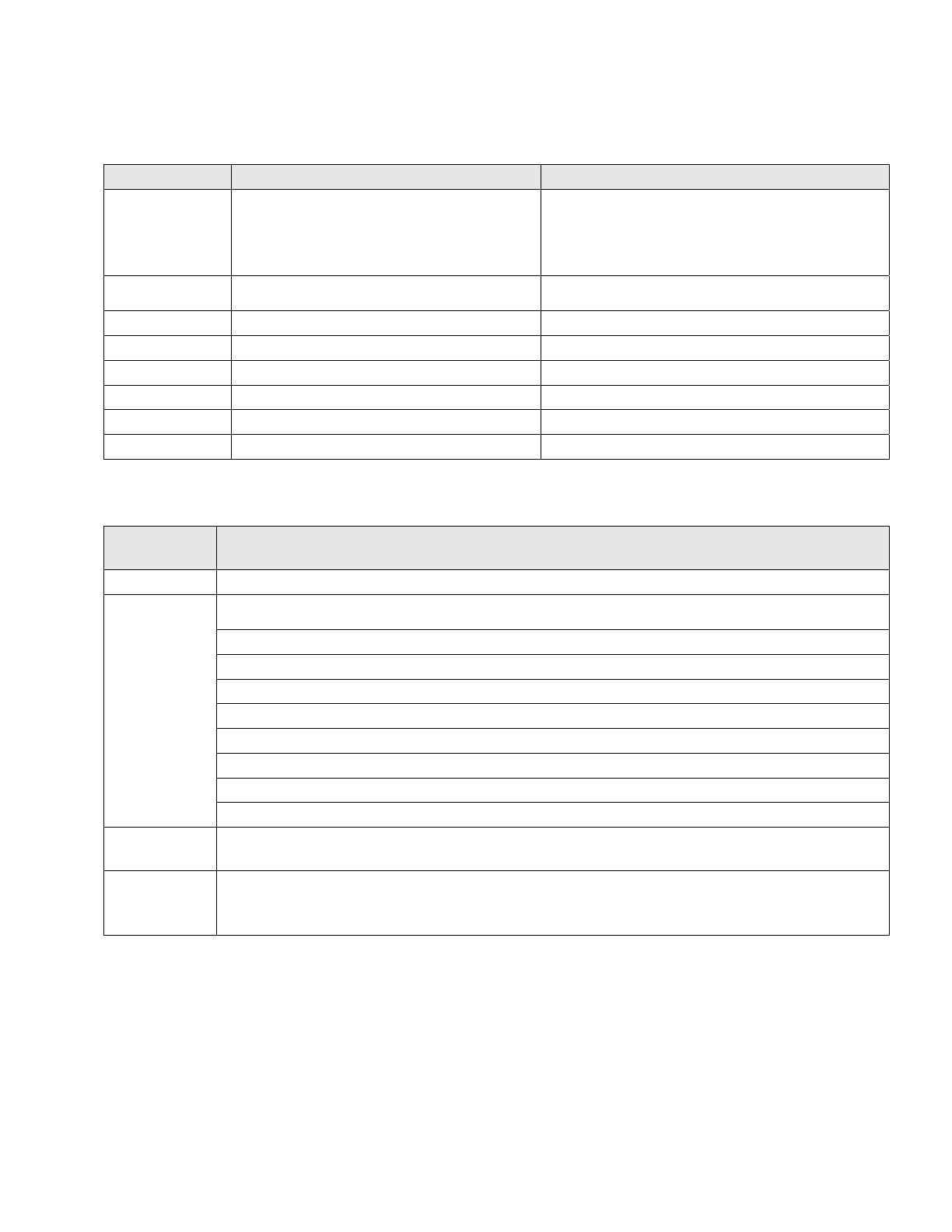
2. Equipment and Software Validated
Provider Hardware Component Software Version
Avaya Avaya Communication Server 1000E
7.50Q 7.50.17 (see Table 2 for applied
updates)
Avaya Avaya 1120E IP Deskphone UNIStim: 0624C8A
Avaya Avaya 1165e IP Deskphone SIP: 04.00.04.00
Avaya Avaya 1230 IP Deskphone SIP: 04.00.04.00
Avaya Avaya 2007 IP Deskphone UNIStim: 0621C8A
Avaya Avaya IP Softphone 2050PC UNIStim: 4.01.041
Avaya Avaya M3903 Digital Phone N/A
Avaya B179 SIP Conference Phone 2..2
Table 1: Hardware Components and Software Versions
Update
Type
Update Components
Patch None
Service
Pack
cs1000-baseWeb-7.50.17.01-1.i386.000
cs1000-dbcom-7.50.17-01.i386.000
cs1000-sps-7.50.17-01.i386.000
cs1000-linuxbase-7.50.17.04-00.i386.000
cs1000-Jboss-Quantum-7.50.17.01-1.i386.000
cs1000-bcc-7.50.17.03-00.i386.000
cs1000-dmWeb-7.50.17.04-00.i386.001
cs1000-shared-pbx-7.50.17-01.i386.000
cs1000-vtrk-7.50.17-11.i386.000
Deplist
p30588_1, p30550_1, p30613_1, p30618_1, p30621_1, p30565_1, p30597_1,
p30595_1, p30591_1, p30560_1, p30594_1, p30619_1
Loadware
IPMG TYPE CSP/SW MSP APP FPGA BOOT DBL1 DBL2
4 0 MGC BD01 AB01 BA07 AA18 BA07 DSP1AB03 N/A
Table 2: CS1000E Applied Updates
FS; Reviewed:
SPOC 06/8/2011
Solution & Interoperability Test Lab Application Notes
©2011 Avaya Inc. All Rights Reserved.
4 of 37
B179-CS1KR75
3. Configure Avaya Communication Server 1000
This section describes the steps to configure the following, using CS 1000 Element Manager:
SIP Line service
SIP Line D-Channel
Application Module Link (AML)
Value Added Server (VAS)
Zone for SIP phones
SIP Line Route Data Block (RDB)
SIP Line Virtual Trunk
Media Gateway Controller
SIP Line telephone corresponding to the B179 SIP Conference Phone
It is assumed that basic installation and configuration of the CS 1000 call server, signaling
server, and node have been completed. Additional configuration details are provided in [1, 2].
3.1. Log in to Element Manager (EM)
Access the Unified Communications Management (UCM) web based interface by using the URL
“http://<ip-address>” in an Internet browser window, where “<ip-address>” is the IP address of
the call server. Note that the IP address for the Call Server may vary, and in this case
“10.7.7.61” is used. Log in with the appropriate user ID and password.
FS; Reviewed:
SPOC 06/8/2011
Solution & Interoperability Test Lab Application Notes
©2011 Avaya Inc. All Rights Reserved.
5 of 37
B179-CS1KR75
The following Unified Communications Management screen will be displayed. Click on
the Element Name corresponding to the Element Type of “CS1000”.
The CS 1000 Element Manager page appears as shown below.
FS; Reviewed:
SPOC 06/8/2011
Solution & Interoperability Test Lab Application Notes
©2011 Avaya Inc. All Rights Reserved.
6 of 37
B179-CS1KR75
3.2. Enable SIP Line Service
Select Customers in the left pane. The Customers screen is displayed. Click the link
associated with the appropriate customer, in this case 00. The system can support more than one
customer with different network settings and options. In the sample configuration, only one
customer was configured on the system.
FS; Reviewed:
SPOC 06/8/2011
Solution & Interoperability Test Lab Application Notes
©2011 Avaya Inc. All Rights Reserved.
7 of 37
B179-CS1KR75
The Customer Details screen is displayed next. Select SIP Line Service to edit its parameters.
FS; Reviewed:
SPOC 06/8/2011
Solution & Interoperability Test Lab Application Notes
©2011 Avaya Inc. All Rights Reserved.
8 of 37
B179-CS1KR75
Check the SIP Line Service checkbox, enter an appropriate User Agent DN prefix
1
, and click
Save.
3.3. Enable SIP Line Service on Telephony Node
On the Element Manager page, navigate to System IP Network Nodes: Servers, Media
Cards. Note the IP address of the Node, as it will be used in configuring the B179 later. Select
the Node ID on which SIP Line service is to be enabled.
Figure 2: CS 1000 Node Screen
1
The User Agent DN Prefix is used to form the User Agent DN. See Section 3.11.
FS; Reviewed:
SPOC 06/8/2011
Solution & Interoperability Test Lab Application Notes
©2011 Avaya Inc. All Rights Reserved.
9 of 37
B179-CS1KR75
Scroll down the top section to display the Applications section on the right, and click on SIP
Line.
Figure 3: Node Details Screen
The SIP Line Configuration Details page is displayed. Check Enable gateway service on this
node next to SIP Line Gateway Application:. Then click Save.
FS; Reviewed:
SPOC 06/8/2011
Solution & Interoperability Test Lab Application Notes
©2011 Avaya Inc. All Rights Reserved.
10 of 37
B179-CS1KR75
Return to the Node Details Screen (Figure 3) and click on Voice Gateway (VGW) and Codecs.
For G.722 and G.729 support, check Enabled next to Codec G.722: and Codec G.729:. If
G.729 Annex B (silence suppression) is desired as in the sample configuration, check the Voice
Activity Detection (VAD) checkbox. Note that the VAD setting should be consistent with the
VAD setting in the B179 configuration (see Section 4.2 Figure 9). Click Save. Then click Save
on the Node Details screen (Figure 3).
Figure 4 – Node Codec Selection
Select Transfer Now on the Node Saved page as shown below.
FS; Reviewed:
SPOC 06/8/2011
Solution & Interoperability Test Lab Application Notes
©2011 Avaya Inc. All Rights Reserved.
11 of 37
B179-CS1KR75
Once the transfer completes, the Synchronize Configuration Files (Node ID <id>) page is
displayed.
Check the appropriate Call Server and click Start Sync. The screen will automatically refresh
until the synchronization is finished. The Synchronization Status field will update from Sync
required (as shown) to Synchronized (not shown). After synchronization completes, click
Restart Applications to use the new SIP Gateway settings.
3.4. Configure SIP Line D-Channel
On the left column menu of the main Element Manager page, navigate to Routes and Trunks
D-Channels. Under the Configuration section, select a D-Channel number from the Choose a
D-Channel Number list (channel 3 in the sample configuration), and select DCH for the type.
Click to Add.
FS; Reviewed:
SPOC 06/8/2011
Solution & Interoperability Test Lab Application Notes
©2011 Avaya Inc. All Rights Reserved.
12 of 37
B179-CS1KR75
The D-Channels Property Configuration screens below show the parameter values after
configuring the D-channel. DCIP is selected for D channel Card Type, Meridian Meridian1
(SL1) is selected for Interface type for D-channel, and an appropriate Designator is entered.
The remaining parameters have their default values.
Click the Basic options (BSCOPT) link to expand that section. Click Edit to configure Remote
Capabilities.
Figure 5 – D-Channel Basic Options
FS; Reviewed:
SPOC 06/8/2011
Solution & Interoperability Test Lab Application Notes
©2011 Avaya Inc. All Rights Reserved.
13 of 37
B179-CS1KR75
The Remote Capabilities Configuration page is displayed. Select the Message waiting
interworking with DMS-100 (MWI) check box,
2
and the Network name display method 2
(ND2) check box. At the bottom of the Remote Capabilities Configuration page, click Return
- Remote Capabilities (not shown), and the D-Channel Property Configuration page
reappears. Click on Submit (see lower left in Figure 5).
2
Note that although the Avaya B179 Conference Telephone does not support Message Waiting Indicator, this D
channel can also be used for other SIP Line IP telephones that do support it, so it is enabled here for that purpose.
FS; Reviewed:
SPOC 06/8/2011
Solution & Interoperability Test Lab Application Notes
©2011 Avaya Inc. All Rights Reserved.
14 of 37
B179-CS1KR75
3.5. Configure Application Module Link (AML)
On the left column menu of the main Element Manager page, navigate to System Interfaces
Application Module Link, and click Add (not shown). The New Application Module Link
page is displayed. Enter the AML port number in the Port number text box. The SIP Line
Service can use ports 32 through 127. In the sample configuration, the SIP Line Service is
configured to use port 32. Enter an appropriate Description. Click Save to save the
configuration.
3.6. Configure Value Added Server (VAS)
On the left column menu of the main Element Manager page, navigate to System Interfaces
Value Added Server. Click Add and then click Ethernet LAN Link on the Add Value
Added Server page that is displayed next (not shown). On the Ethernet Link page that is
displayed next (not shown), enter a Value added server ID (64 in the sample configuration),
and select the AML number created in the previous section for Ethernet LAN Link. Ensure
that the Application Security check box is unchecked. Click Save (not shown). The screen
below shows the result of adding the value added server.
FS; Reviewed:
SPOC 06/8/2011
Solution & Interoperability Test Lab Application Notes
©2011 Avaya Inc. All Rights Reserved.
15 of 37
B179-CS1KR75
3.7. Configure Zone for SIP Phones
On the left column menu of the main Element Manager page, navigate to System IP Network
Zones. On the Zones page, select Bandwidth Zones (not shown), and on the Zone Basic
Property and Bandwidth Management page, enter a Zone number (ZONE) and an
appropriate Description. Defaults can be used for the remaining fields. Click Save.
3.8. Configure SIP Line Route Data Block (RDB)
On the left column menu of the main Element Manager page, navigate to Routes and Trunks
Routes and Trunks. Click Add route for the appropriate customer number.
The following screen shows the parameter settings after the route has been added. Set the
following parameters and leave default values for the remaining parameters. The Basic Route
Options, Network Options, General Options, and Advanced Configurations sections (not
shown) can be left at the defaults. Click Submit (not shown) to save the configuration changes.
FS; Reviewed:
SPOC 06/8/2011
Solution & Interoperability Test Lab Application Notes
©2011 Avaya Inc. All Rights Reserved.
16 of 37
B179-CS1KR75
Route number (ROUT) Select a route number
Designator field for trunk (DES) Enter an appropriate name
Trunk type (TKTP) Select TIE trunk data block (TIE)
Incoming and outgoing trunk (ICOG) Select Incoming and Outgoing
(IAO)
Access code for the trunk route (ACOD) Enter the access code
The route is for a virtual trunk route (VTRK) Check the box
Zone for codec selection and bandwidth Enter a zone
3
management (ZONE)
Node ID of signaling server of this route (NODE) Enter the node ID of the SIP Line
Gateway
Protocol ID for the route (PCID) Select SIP Line (SIPL)
Integrated services digital network option (ISDN) Check the box
Mode of operation (MODE) Select Route uses ISDN Signaling
Link (ISLD)
D channel number (DCH) Enter the D-channel number
Interface type for route (IFC) Select Meridian M1 (SL1)
Network calling name allowed (NCNA) Check the box
Network call redirection (NCRD) Check the box
Trunk route optimization (TRO) Check the box
3
Note that this must be a zone of type VTRK and must be different than the zone created for the SIP phones in
Section 3.7. In the sample configuration, the VTRK zone was 1.
FS; Reviewed:
SPOC 06/8/2011
Solution & Interoperability Test Lab Application Notes
©2011 Avaya Inc. All Rights Reserved.
17 of 37
B179-CS1KR75
3.9. Configure SIP Line Virtual Trunk
When the Routes and Trunks screen is displayed after adding the route in Section 3.8, click
Add trunk corresponding to the newly added route to add new trunk members. The following
screen shows the parameter settings for one of the trunks after they have been added. Set the
following parameters and leave default values for the remaining parameters. Click Save to save
the configuration changes.
Multiple trunk input number Enter the number of trunks (only shown
when adding trunks)
Trunk data block Select IP Trunk (IPTI)
Terminal number An available terminal number.
Designator field for trunk A descriptive text.
Extended trunk Select Virtual trunk (VTRK)
Route number, Member number Current route number and starting member.
(only shown when adding trunks)
Card density Select Octal Density (8D)
Start arrangement Incoming Select Wink or Fast Flash (WNK)
Start arrangement Outgoing Select Wink or Fast Flash (WNK)
Trunk group access restriction Desired trunk group access restriction level.
Channel ID for this trunk An available starting channel ID.
FS; Reviewed:
SPOC 06/8/2011
Solution & Interoperability Test Lab Application Notes
©2011 Avaya Inc. All Rights Reserved.
18 of 37
B179-CS1KR75
3.10. Configure Media Gateway Controller
This section describes configuration of the G.729 audio codec for the Media Gateway Controller
(MGC) to support calls between the B179 and non-IP telephones. On the left column menu of
the main Element Manager page, navigate to IP Network Media Gateways. Click on the
IPMG that supports the digital and analog phones in the system.
On the IPMG Property Configuration screen, click Next (not Shown). Expand the VGW and
IP phone codec profile section. In that section, check the Select checkbox next to and expand
the Codec G729A section.
FS; Reviewed:
SPOC 06/8/2011
Solution & Interoperability Test Lab Application Notes
©2011 Avaya Inc. All Rights Reserved.
19 of 37
B179-CS1KR75
If Annex B support is desired as in the sample configuration, check the VAD checkbox. Note
that the VAD setting should be consistent with the VAD setting in the B179 configuration (see
Section 4.2 Figure 9). Click Save.
Figure 6 – MGC Codec Selection
FS; Reviewed:
SPOC 06/8/2011
Solution & Interoperability Test Lab Application Notes
©2011 Avaya Inc. All Rights Reserved.
20 of 37
B179-CS1KR75
When the Media Gateway screen returns, select the radio button for the IPMG and click Reboot.
3.11. Configure SIP Line Telephone
This section describes the screens for configuring a SIP Line telephone to support the Avaya
B179 Conference Telephone. On the left column menu of the main Element Manager page,
navigate to Phones. On the Search For Phones page, click Add….
1 / 1

Avaya B179 Application Note

Category
Networking
Type
Application Note

Avaya B179 is a SIP VoIP conference phone that offers exceptional audio quality and a host of features designed to enhance your communication experience. With its advanced microphone and speaker system, the B179 delivers crystal-clear audio, ensuring that every participant in your conference call is heard loud and clear. The phone also features a sleek and modern design, making it a stylish addition to any office or conference room.

Ask a question and I''ll find the answer in the document

Finding information in a document is now easier with AI

Ask the document