Page is loading ...

Crestron MP2 & MP2E
2-Series Integrated AV Control System
Operations Guide

This document was prepared and written by the Technical Documentation department at:
Crestron Electronics, Inc.
15 Volvo Drive
Rockleigh, NJ 07647
1-888-CRESTRON
All brand names, product names and trademarks are the property of their respective owners.
©2006 Crestron Electronics, Inc.

Crestron MP2 & MP2E 2-Series Integrated AV Control System
Contents
2-Series Integrated AV Control System: MP2 & MP2E 1
Introduction ...............................................................................................................................1
Features and Functions................................................................................................ 1
Applications.................................................................................................................3
Internal Block Diagram ............................................................................................... 5
Specifications ..............................................................................................................6
Physical Description....................................................................................................8
Industry Compliance ................................................................................................. 13
Setup ........................................................................................................................................14
Network Wiring.........................................................................................................14
Identity Code ............................................................................................................. 14
Hardware Hookup .....................................................................................................14
Programming Software............................................................................................................20
Earliest Version Software Requirements for the PC ................................................. 20
Programming with Crestron SystemBuilder.............................................................. 20
Programming with SIMPL Windows ........................................................................ 20
Programming with Digital Media Tools....................................................................21
Example Program...................................................................................................... 22
Uploading and Upgrading........................................................................................................ 23
Establishing Communication.....................................................................................23
Programs and Firmware ............................................................................................24
Operation .................................................................................................................................25
Problem Solving ......................................................................................................................26
Troubleshooting......................................................................................................... 26
Check Network Wiring..............................................................................................29
Reference Documents................................................................................................ 30
Further Inquiries ........................................................................................................30
Future Updates ..........................................................................................................30
Software License Agreement................................................................................................... 31
Return and Warranty Policies .................................................................................................. 33
Merchandise Returns / Repair Service ...................................................................... 33
CRESTRON Limited Warranty.................................................................................33
Operations Guide – DOC. 6175A Contents • i


Crestron MP2 & MP2E 2-Series Integrated AV Control System
2-Series Integrated AV Control
System: MP2 & MP2E
2-Series Integrated AV Control
System: MP2 & MP2E
Introduction Introduction
Features and Functions
• 2-Series engine built on Motorola’s 32-bit 257 MIPS Coldfire
®
technology
• 36 MB of Internal Memory
1
• Integrated AV Switcher/Processor
• 4x2 high-bandwidth video switch with video signal detectors,
expandable with the Crestron C2N-MMS
• 7x1 stereo audio switch
• 6-band graphic/parametric EQ
• Built-in volume, bass and treble controls
• Cresnet
®
port – master/slave selectable
• 10/100 Ethernet with SSL encryption
2
• Crestron e-Control
®
2 enabled
2
• RoomView
®
enabled
2
• Two Com ports (RS-232/422/485)
• Four IR/serial ports
• Four Versiport I/O ports
• Four Low-voltage relay ports
• IR Wireless compatible using CNXRMIRD
• External power supply included
• Single-space EIA rack-mountable
1. For more information on internal memory, refer to “2-Series Memory & Directory Structure” in the
latest version of the Crestron 2-Series Control Systems Reference Guide (Doc. 6256), which is
available from the Crestron website (http://www.crestron.com/manuals
).
2. MP2E only.
Operations Guide – DOC. 6175A Series-2 Integrated AV Control System: MP2 & MP2E • 1

2-Series Integrated AV Control System Crestron MP2 & MP2E
2-Series Engine
At the heart of the MP2 & MP2E is the powerful 32-bit Freescale ColdFire
®
processor. Crestron's exclusive enhanced real-time operating system makes the MP2
& MP2E the fastest, most reliable control systems available.
Cresnet
®
Cresnet is the communications backbone for many Crestron touchpanels, keypads,
lighting controls and other devices. The Cresnet bus is a simple, yet flexible 4-wire
network that provides rock-solid bidirectional communication and power for up to
252 Cresnet devices.
Cresnet Slave Mode
Selectable Cresnet Slave Mode enables the MP2 & MP2E to be configured as
Cresnet slave devices, effectively transforming them into Cresnet expansion
modules. Such flexibility can offer a cost-effective solution for system expansion,
providing a host of additional control ports in a single module.
Ethernet (MP2E only)
Crestron pioneered the IP-based control system to harness the vast possibilities of
Ethernet and the Internet for remote control, monitoring, programming and
diagnostics. The MP2E is designed to deliver the world's most advanced IP control
solution. The high-speed Ethernet port enables a full-duplex 10/100 Ethernet
connection with built-in Web server and email client and support for both static and
dynamic IP addressing.
Crestron e-Control
®
2 (MP2E only)
Crestron's award-winning e-Control 2 XPanel solutions offer the most flexible range
of IP control possibilities available. Using a Windows
®
computer or CE/PocketPC™
PDA device, e-Control 2 provides an amazing control GUI that looks and behaves
just like a Crestron Isys
®
touchpanel.
Crestron RoomView
®
(MP2E only)
Every Ethernet-enabled 2-Series control system works directly with Crestron's
exclusive RoomView Help Desk software for the industry's most comprehensive
facility-wide asset management solution.
SSL (MP2E only)
All Ethernet-enabled 2-Series control systems support SSL (Secure Sockets Layer),
the industry standard for protecting sensitive network communications.
2 • 2-Series Integrated AV Control System: MP2 & MP2E Operations Guide – DOC. 6175A

Crestron MP2 & MP2E 2-Series Integrated AV Control System
Applications
The following diagrams show an MP2E in a basic room master mode configuration
with A/V switching and control and with an MMS multimedia switch.
Example of a Basic Room Master Mode Configuration with A/V Switching and Control
Operations Guide – DOC. 6175A Series-2 Integrated AV Control System: MP2 & MP2E • 3

2-Series Integrated AV Control System Crestron MP2 & MP2E
Example of a Basic Room Master Mode Configuration with MMS Multimedia Switch
4 • 2-Series Integrated AV Control System: MP2 & MP2E Operations Guide – DOC. 6175A

Crestron MP2 & MP2E 2-Series Integrated AV Control System
Internal Block Diagram
The following diagram represents the AV switching abilities of the MP2 & MP2E.
The diagram depicts the audio and video switching matrices and the equalization
module available for the audio inputs. For more information refer to “Operation” on
page 25.
AV Internal Block Diagram of the MP2 & MP2E
Operations Guide – DOC. 6175A Series-2 Integrated AV Control System: MP2 & MP2E • 5

2-Series Integrated AV Control System Crestron MP2 & MP2E
Specifications
Specifications for the MP2 & MP2E are listed in the following table.
MP2 & MP2E Specifications
SPECIFICATION DETAILS
Processor
CPU
32-bit Freescale Coldfire
Microprocessor
Processing Speed 257 MIPS (Dhrystone 2.1 benchmark)
Memory
SDRAM 32 MB
NVRAM 256 kB
Flash 4 MB
Operating System
Real-time preemptive multi-
threaded/multitasking kernel; FAT32 file
system with long names; supports SIMPL
Windows and SIMPL+
Ethernet (MP2E only)
10/100BaseT, auto-negotiating, full/half
duplex, static IP or DHCP/DNS, SSL,
TCP/IP, UDP/IP, CIP, SMTP, built-in Web
server and e-mail client; supports Crestron
e-Control
2 Xpanel and RoomView
applications
Video
Features
4x2 composite matrix switcher
or 2x1 Y/C (S-Video) switcher
Bandwidth 100 MHz minimum
Crosstalk -60 dB
Audio
Features
7x1 stereo audio switcher and digital
parametric and/or graphic equalizer*
Master Volume
-80 dB to +20 dB, in 1 dB steps
(balanced I/O)
Input Compensation
±10 dB per input channel, 0.1 dB steps
from DMT, 0.2 dB steps from SIMPL
Bass Gain Range ±15 dB, 0.5 dB steps at 100 Hz
Treble Gain Range ±15 dB, 0.5 dB steps at 10 kHz
Equalization Modes
6-band parametric;
3-band graphic + 3-band parametric;
5-band graphic + 1-band parametric;
5-band graphic + 1-band parametric
(speech optimized)
PEQ Filter Gain
±12 dB, 0.01 dB steps from DMT;
+24/-36 dB, 0.1 dB steps from SIMPL
PEQ Filter Bandwidth
0.02 to 2.0 octaves (1.0 to 3.0 for shelving)
from DMT, 0.02 to 3.5 octaves from SIMPL
PEQ Filter Center Frequency
25 Hz - 19.9 kHz from DMT:
5 Hz - 24 kHz from SIMPL, 1 Hz steps
PEQ Filter Types
Low pass, high pass, EQ filter
(peaking/notching), bass shelf and treble
shelf
(Continued on following page)
6 • 2-Series Integrated AV Control System: MP2 & MP2E Operations Guide – DOC. 6175A

Crestron MP2 & MP2E 2-Series Integrated AV Control System
MP2 & MP2E Specifications (Continued)
SPECIFICATION DETAILS
Audio (Continued)
GEQ Filter Gain
±12 dB, 0.1 dB steps from DMT;
±10 dB, 0.1 dB steps from SIMPL
GEQ Filter Center
Frequencies
63, 250, 1k, 4k, 10k Hz (5-band);
160, 600, 1k, 2.5k, 5k Hz (5-band speech);
250, 1k, 4k Hz (3-band)
Frequency Response 20 Hz - 20 kHz +0/-0.5 dB
THD + Noise <0.005% at 1 kHz, A-weighted, max I/O
S/N Ratio >97 dB, 20 Hz - 20 kHz A-weighted
Channel Separation >100 dB at 1 kHz, 90 dB 20 Hz - 20 kHz
Crosstalk > -90 dB 20 Hz - 20 kHz
Common Mode Rejection >85 dB 20 Hz - 20 kHz
Power Requirements
18 Watts (0.75 Amp) @ 24 Volts DC
(PW-2410RU power supply included)
Available Cresnet Power
7 Watts using PW-2410RU (included) or 32
Watts using PW-2420RU (sold separately)
Cresnet Power Usage
18 Watts (0.75 Amp @ 24 Volts DC) with
no power supply connected to the 24VDC
connector
Environmental
Temperature 41º to 113ºF (5º to 45ºC)
Humidity 10% to 90% RH (non-condensing)
Enclosure
Black metal, 1U 19” rack-mountable
(rack ears included)
Dimensions
Height 1.70 in (4.32 cm)
Width
19.00 in (48.26 cm) with ears;
17.03 in (43.25 cm) without ears
Depth 9.09 in (23.08 cm)
Weight 3.54 lbs (1.61 kg)
Included Accessories
PW-2410RU 25 Watt Regulated Universal Power Supply
Available Accessories
C2N-MMS Video and RGBHV switcher
PW-2420RU 50 Watt Regulated Universal Power Supply
C2N-HBLOCK Cresnet Network Distribution Block
CNSP-XX Custom Serial Interface Cable
IRP2 IR Probe
CNXRMIRD IR Receiver
* Minimum operating firmware version 3.26 is required to operate the parametric equalizer feature.
Operations Guide – DOC. 6175A Series-2 Integrated AV Control System: MP2 & MP2E • 7

2-Series Integrated AV Control System Crestron MP2 & MP2E
Physical Description
This section provides information on the connections, controls and indicators
available on your MP2 & MP2E.
MP2 Physical Views
MP2E Physical Views
8 • 2-Series Integrated AV Control System: MP2 & MP2E Operations Guide – DOC. 6175A

Crestron MP2 & MP2E 2-Series Integrated AV Control System
MP2 & MP2E Overall Dimensions
19.00 in
(48.26 cm)
1.70 in
(4.32 cm)
17.03 in
(43.25 cm)
4
55
32211
77
6
8
9 10
11
12
13
14
15
16 17
1318
19 20
9.09 in
(23.08 cm)
Connectors, Controls & Indicators
#
CONNECTORS
1
,
CONTROLS & INDICATORS
DESCRIPTION
1 PWR LED
Indicates 24 Volts DC power supplied from Cresnet control network
or included PW-2410RU power supply.
2 NET LED Indicates communication with Cresnet system.
3 MSG LED
2
Illuminates when a message is detected. To decipher content,
examine the message through the Crestron Toolbox™.
(Continued on following page)
Operations Guide – DOC. 6175A Series-2 Integrated AV Control System: MP2 & MP2E • 9

2-Series Integrated AV Control System Crestron MP2 & MP2E
Connectors, Controls & Indicators (Continued)
#
CONNECTORS
1
,
CONTROLS & INDICATORS
DESCRIPTION
4 LAN LEDs
3
LNK – Indicates when there is a connection to the rear panel LAN
port.
ACT – Indicates communication (activity) at the rear panel LAN port.
5 RESET BUTTONS
HW-R - Initiates system hardware reset.
SR-R - Pressing this in combination with HW-R button performs a
system restart without loading the program. Pressing it alone while
the system is running restarts the program.
6
VIDEO IN (1 – 4)
1
2
3
4
VIDEO IN
(4) BNC female comprising (4) composite or (2) S-video inputs.
Input impedance: 75 Ω.
For S-video use connectors 1 (Y1) & 2 (C1) for first input and 3 (Y2)
& 4 (C2) for second input.
7
VIDEO OUT (1 – 2)
1
2
VIDEO OUT
(2) BNC female comprising (2) composite or (1) S-video outputs.
Output impedance: 75 Ω.
8
AUDIO IN (1 - 2)
+
(2) 5-pin 3.5 mm detachable terminal blocks comprising (2)
balanced/unbalanced stereo line-level inputs.
Input impedance: 15 kΩ balanced, 10 kΩ unbalanced;
Maximum input level: 4 V
RMS
balanced, 2 V
RMS
unbalanced.
9
AUDIO IN (3 - 7)
(5) 3-pin 3.5 mm detachable terminal blocks comprising (5)
unbalanced stereo line-level inputs.
Input impedance: 10 kΩ; Maximum input level: 2 V
RMS
.
10
COM (A – B)
4, 5, 6
COM BCOM A
(2) DB9 male, bidirectional RS-232/422/485 ports. Up to 115.2k
baud, hardware and software handshaking support. All ports support
C2N-NPA8 Network Poll Accelerator
7
.
PIN DIRECTION DESCRIPTION
1*
To MP2 or MP2E
(RXD-) RS-422 Receive Data (Idles low)
2
To MP2 or MP2E
(RXD) RS-232 Received Data
3
From MP2 or MP2E
(TXD) RS-232 Transmitted Data
4
From MP2 or MP2E
(TXD+) RS-422 Transmit Data (Idles high)
5
RS-232 and RS-422 Signal Common
6
To MP2 or MP2E
(RXD+) RS-422 Receive Data (Idles high)
7
From MP2 or MP2E
(RTS) RS-232 Request to Send
8
To MP2 or MP2E
(CTS) RS-232 Clear to Send
9
From MP2 or MP2E
(TXD-) RS-422 Transmit Data (Idles low)
* RS-422 transmit and receive are balanced signals requiring two lines plus
a ground in each direction. RXD+ and TXD+ should idle high (going low at
start of data transmission). RXD- and TXD- should idle low (going high at
start of data transmission). If necessary, RXD+/RXD- and TXD+/TXD-
may be swapped to maintain correct signal levels.
11
GROUND
(1) 6-32 screw, chassis ground lug.
G++-
2
RL
+G--
1
RL
-
G
R3
L
G
7RL
(Continued on following page)
10 • 2-Series Integrated AV Control System: MP2 & MP2E Operations Guide – DOC. 6175A

Crestron MP2 & MP2E 2-Series Integrated AV Control System
Connectors, Controls & Indicators (Continued)
#
CONNECTORS
1
,
CONTROLS & INDICATORS
DESCRIPTION
12
LAN
3, 8
(1) 8-wire RJ-45 with 2 LED indicators;
10/100BaseT Ethernet port;
Green LED indicates link status.
Yellow LED indicates Ethernet activity.
TYPE PIN SIGNALS
1 TD+
2 TD-
3 RD+
4 Connected to pin 5
5 Connected to pin 4
6 RD-
7 Connected to pin 8
8-Position
RJ-45
8 Connected to pin 7
13
NET
9
Four-position terminal block connector for data and power.
Connects to Cresnet control network.
Pin 1 (24) Power
Pin 2 (Y) Data
Pin 3 (Z) Data
Pin 4 (G) Ground
14
AUDIO OUT (L/R)
+ - G + -
L R
(1) 5-pin 3.5 mm detachable terminal block;
Balanced/unbalanced stereo line-level output;
Output impedance: 200 Ω balanced, 100 Ω unbalanced;
Maximum output level: 3.6 V
RMS
balanced, 1.8 V
RMS
unbalanced.
15
INFRARED-SERIAL
OUTPUT (A – D)
10, 11
A B C D
S G S G S G S G
IR SERIAL OUT
(4) 2-pin 3.5 mm detachable terminal blocks IR/Serial output ports.
IR output up to 1.2 MHz; 1-way serial TTL/RS-232 (0-5 Volts) up to
115.2k baud. Individual signal generator per port, allowing
simultaneous firing of all ports.
16
IR IN
T R S
IR IN
(1) 3-pin 3.5 mm detachable terminal block;
For connection of the CNXRMIRD IR Receiver (sold separately);
Allows IR wireless control from Crestron or third-party remotes using
RC-5 IR commands.
17
I/O
12, 13
I/O
1
42G3
(1) 5-pin 3.5 mm detachable terminal block comprising (4) digital
input/output or analog input ports (referenced to GND);
Digital Input: Rated for 0-24 Volts DC, input impedance 20 kΩ, logic
threshold 1.24 Volts DC;
Digital Output; 250 mA sync from maximum 24 Volts DC, catch
diodes for use with “real world” loads;
Analog Input: Rated for 0-10 Volts DC, protected to 24 Volts DC
maximum, input impedance 20 kΩ;
Programmable 5 Volts, 2 kΩ pull-up resistor per pin.
18
RELAY OUT
1 2 3 4
RELAY OUT
(1) 8-pin 3.5 mm detachable terminal block comprising (4) normally
open, isolated relays;
Rated 1 Amp, 30 Volts AC/DC,
MOV arc suppression across contacts.
(Continued on following page)
Operations Guide – DOC. 6175A Series-2 Integrated AV Control System: MP2 & MP2E • 11

2-Series Integrated AV Control System Crestron MP2 & MP2E
Connectors, Controls & Indicators (Continued)
#
CONNECTORS
1
,
CONTROLS & INDICATORS
DESCRIPTION
19
COMPUTER
14
COMPUTER
(1) DB9 female, RS-232 computer console port.
Connector is used when programming with a PC. The port is
modem compatible (modem and PC cables not included). Supports
baud rate of up to 115 kB. Use with a standard DB9 straight through
cable. Pins 1, 4, 6 and 9 are not used but may be connected.
PIN # ABBREVIATION DESCRIPTION
2 TXD Transmit Data
3 RXD Receive Data
5 SG Signal Ground
7 CTS Clear To Send
8 RTS Request To Send
20
24 VDC
9
(1) 2 mm barrel DC power jack, 24 Volt DC power input;
(PW-2410RU power included);
Passes through to NET port to power Cresnet devices.
24VDC
2.0A
1. Interface connectors for NET, Infrared-Serial, I/O and Relay Output ports are provided with the unit.
2. This LED was labeled “ERR” on units manufactured prior to 2005. It is functionally the same; only the labeling has changed.
3. MP2E only.
4. The pinout of each 9-pin port is non-standard; it contains RS-422 pins in addition to RS-232. This may result in a conflict with some equipment
and therefore all nine pins should not be used. Only the required pins for each communication type should be connected. For RS-232 and –422,
pins 2, 3, 5, 7 and 8 are wired straight through.
5. Data Set Ready (DSR) and Data Terminal Ready (DTR) are not supported.
6. To support RS-485, tie pin 1 (RXD-) to pin 9 (TXD-)
and pin 4 (TXD+) to pin 6 (RXD+) in the cable.
COM (DB9) CONNECTOR RS-485 BUS
(Refer to table at right.)
Tie Pins 1 & 9 -
Tie Pins 4 & 6 +
Pin 5 G
7. The Cresnet Poll Accelerator effectively increases the network speed, fan-out and device addresses by a factor of 8 for each Poll Accelerator added
to the system.
8. To determine which is pin 1 on the cable, hold the cable so that the end of the eight pin modular jack is facing away from you, with the clip down
and copper side up. Pin 1 is on the far left.
9. Use care in wiring installations to avoid applying 24 VDC to Cresnet wiring from an AC power pack as well as from a system device that contains
its own power supply. Although this condition should not cause any damage, Crestron does not recommend it. In those network configurations that
require more power than can be supplied by the primary power supply alone, disconnect the +24 VDC Cresnet wire from those devices that will be
powered by an AC power pack.
10. Transmission levels on the infrared–serial output connectors are in the 0 to +5 VDC range, which may not be compatible with all RS-232 devices.
11. When configured for one-way RS-232 serial data, you cannot stack multiple RS-232 devices or combine/mix with IR devices on the same port.
12. Digital outputs are TTL values and may not work with devices requiring a “dry” contact closure (e.g. low voltage motor controllers).
13. Ports can be in or out but not both. For additional information, refer to the SIMPL Windows help file.
14. DTR (pin 4) and DSR (pin 6) are not normally used.
12
• 2-Series Integrated AV Control System: MP2 & MP2E Operations Guide – DOC. 6175A

Crestron MP2 & MP2E 2-Series Integrated AV Control System
Industry Compliance
As of the date of manufacture the MP2 & MP2E have been tested and found to
comply with specifications for CE marking and standards per EMC and
Radiocommunications Compliance Labelling.
NOTE: This device complies with part 15 of the FCC rules. Operation is subject to
the following two conditions: (1) this device may not cause harmful interference and
(2) this device must accept any interference received, including interference that may
cause undesired operation.
This equipment has been tested and found to comply with the limits for a Class B
digital device, pursuant to part 15 of the FCC Rules. These limits are designed to
provide reasonable protection against harmful interference in a residential
installation. This equipment generates, uses and can radiate radio frequency energy
and if not installed and used in accordance with the instructions, may cause harmful
interference to radio communications. However, there is no guarantee that
interference will not occur in a particular installation. If this equipment does cause
harmful interference to radio or television reception, which can be determined by
turning the equipment off and on, the user is encouraged to try to correct the
interference by one or more of the following measures:
Reorient or relocate the receiving antenna.
Increase the separation between the equipment and receiver.
Connect the equipment into an outlet on a circuit different from that to
which the receiver is connected.
Consult the dealer or an experienced radio/TV technician for help.
Operations Guide – DOC. 6175A Series-2 Integrated AV Control System: MP2 & MP2E
• 13

2-Series Integrated AV Control System Crestron MP2 & MP2E
Setup
Network Wiring
When wiring the network, consider the following:
• Use Crestron Certified Wire.
• Use Crestron power supplies for Crestron equipment.
• Provide sufficient power to the system.
CAUTION: Insufficient power can lead to unpredictable results or damage
to the equipment. Please use the Crestron Power Calculator to help calculate
how much power is needed for the system
(http://www.crestron.com/calculators
).
• For larger networks, use a Cresnet Hub/Repeater (CNXHUB) to maintain
signal quality.
For more details, refer to “Check Network Wiring” on page 29.
Identity Code
Net ID
The Net IDs of the MP2 & MP2E has been factory set to 02. This Net ID is defined
as the “Master” control system. The Net IDs of multiple MP2 & MP2E devices in
the same system must be unique; this means there will be a master/slave relationship
between units (only the Net ID of the master will be left at 02). Net IDs are changed
from a personal computer (PC) via the Crestron Toolbox™. When setting the Net
ID, consider the following:
• The Net ID of each unit must match an ID code specified in the SIMPL
Windows program.
• Each network device must have a unique Net ID.
For more details, refer to the Crestron Toolbox help file.
IP ID
The IP ID is set within the MP2’s or MP2E’s table using Crestron Toolbox. For
information on setting an IP table, refer to the Crestron Toolbox help file.
The IP IDs of multiple MP2 & MP2E devices in the same system must be unique.
When setting the IP ID, consider the following:
• The IP ID of each unit must match an IP ID specified in the SIMPL
Windows program.
• Each device using IP to communicate with a control system must have a
unique IP ID.
Hardware Hookup
Ventilation
To prevent overheating, do not operate this product in an area that exceeds the
environmental temperature range listed in the table of specifications. Consideration
must be given if installed in a closed or multi-unit rack assembly since the operating
ambient temperature of the rack environment may be greater than the room ambient
temperature. Contact with thermal insulating materials should be avoided on all sides
of the unit.
14
• 2-Series Integrated AV Control System: MP2 & MP2E Operations Guide – DOC. 6175A

Crestron MP2 & MP2E 2-Series Integrated AV Control System
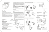
Rack Mounting
The MP2 & MP2E can be mounted in a rack or stacked with other equipment. Two
“ears” are provided with the MP2 & MP2E so that the unit can be rack mounted.
These ears must be installed prior to mounting. Complete the following procedure to
attach the ears to the unit. The only tool required is a #2 Phillips screwdriver.
WARNING: To prevent bodily injury when mounting or servicing this unit in a
rack, take special precautions to ensure that the system remains stable. The following
guidelines are provided to ensure your safety:
• When mounting this unit in a partially filled rack, load the rack from the
bottom to the top with the heaviest component at the bottom of the rack.
• If the rack is provided with stabilizing devices, install the stabilizers before
mounting or servicing the unit in the rack.
NOTE: If rack mounting is not required, rubber feet are provided for tabletop
mounting or stacking. Apply the feet near the corner edges on the underside of the
unit.
NOTE: Reliable earthing of rack-mounted equipment should be maintained.
Particular attention should be given to supply connections other than direct
connections to the branch circuit (e.g. use of power strips).
To install the ears:
1. There are screws that secure each side of the MP2 & MP2E top cover.
Using a #2 Phillips screwdriver, remove the three screws closest to the front
panel from one side of the unit. Refer to the diagram following step 3 for a
detailed view.
2. Position a rack ear so that its mounting holes align with the holes vacated
by the screws in step 1.
3. Secure the ear to the unit with three screws from step 1, as shown in the
following diagram.
Ear Attachment for Rack Mounting (this image shows a 1RU device)
USE COVER SCREWS
4. Repeat procedure (steps 1 through 3) to attach the remaining ear to the
opposite side.
Bussing Strip Installation
The 2-Series integrated AV control system is supplied with two brass bussing strips
to facilitate commoning (linking) of multiple terminal block connections. The
bussing strips are constructed with four terminal block positions and may be
trimmed to size for various applications or different devices. One strip is supplied for
each 8-position terminal block.
Operations Guide – DOC. 6175A Series-2 Integrated AV Control System: MP2 & MP2E
• 15

2-Series Integrated AV Control System Crestron MP2 & MP2E
1. To utilize the bussing strip, determine the number of relays to be
commoned for the equipment being installed. If less than four, the strip can
be trimmed to size with a pair of scissors or wire snips.
2. Loosen the terminal block screws and insert the first leg of the bussing strip
into the first common position of the terminal block. The strip engages the
other common positions automatically.
3. Remove approximately 1/8” of the jacket from the common wire and insert
the conductor into one of the terminal block common positions. Tighten the
terminal block screws to lock the wire and bussing strip into place. Insulate
the strip by folding a piece of ¾” wide vinyl electrical tape (such as Scotch
33+) over the spine and as much of the individual legs as possible. Excess
tape at each end of the strip should be pressed closed, then trimmed to
within approximately 1/16” of the end of the strip.
4. When wiring the remaining conductors, remove approximately 1/8” of the
jacket and insert the wires into the proper terminal block positions. To
prevent the possibility of electrical shorts, it is essential that these
conductors do not touch any uninsulated portion of the bussing strip.
5. Securing a tie wrap around the bussing strip is a useful way to provide
strain relief for the wires connected to the terminal block.
Connect the Device
Make the necessary connections as called out in the illustration that follows this
paragraph. Refer to “Network Wiring” on page 14 before attaching the 4-position
terminal block connector. Apply power after all connections have been made.
When making connections to the MP2 & MP2E, consider the following:
• Use Crestron power supplies for Crestron equipment.
• The included cable cannot be extended.
16
• 2-Series Integrated AV Control System: MP2 & MP2E Operations Guide – DOC. 6175A
/