Page is loading ...

1
TopWorx
TM
TX-Series Valve Controllers
Installation, Operation & Maintenance Manual

2
Emerson™
Emerson is a powerful, global, single source of process improvement
technology and expertise. We help major companies in selected industries
optimize their plants and processes to achieve higher quality, greater
reliability and faster time to market, while steadily advancing productivity
and profitability.
Emerson’s technology know-how and application experience enable us to develop
products and solutions that deliver the proven performance and reliability our customers
expect when looking to build, connect, improve, and maintain their equipment and
automation process.
Driven Without Compromise

Table of Contents
INSTALLATION ON ACTUATOR ................................................................................................................... 4
NORMAL and REVERSE ACTING.................................................................................................................. 4
MOUNTING.......................................................................................................................................................... 4
TXP DIMENSIONS and MATERIALS ............................................................................................................ 5
TXP FLAT TOP DIMENSIONS and MATERIALS ........................................................................................ 6
TXS DIMENSIONS and MATERIALS ............................................................................................................ 7
TXS FLAT TOP DIMENSIONS and MATERIALS ........................................................................................ 8
SHAFT DETAIL ................................................................................................................................................... 9
SENSORS BASIC FUNCTION ........................................................................................................................ 10
SWITCH SETTING............................................................................................................................................ 10
SWITCH OPTION D or S................................................................................................................................... 11
SWITCH OPTION L...........................................................................................................................................12
SWITCH OPTION M or K .................................................................................................................................13
SWITCH OPTION P or R...................................................................................................................................14
SWITCH OPTION E ..........................................................................................................................................15
SWITCH OPTION 12.........................................................................................................................................16
SWITCH OPTION 42/44 and 52/54..................................................................................................................17
SWITCH OPTION 0X........................................................................................................................................18
SWITCH OPTION AS/AM: AS-I .....................................................................................................................21
SWITCH OPTION PB/PM: PROFIBUS ..........................................................................................................22
INTEGRATED PNEUMATIC PILOT .............................................................................................................24
INTEGRATED PNEUMATIC CONTROL VALVES ....................................................................................25
MAINTENANCE ...............................................................................................................................................25
APPROVALS & CERTIFICATIONS.............................................................................................................. 26
PROOF TESTING...............................................................................................................................................27
SAFETY FUNCTIONS ......................................................................................................................................28
SAFE USE............................................................................................................................................................29
RECOMMENDED OPERATING TEMPERATURES ...................................................................................29
3

Installation on Actuator
4
Normal and Reverse Acting
Normal acting is full clockwise (CW) when the process valve is closed and counterclockwise (CCW) when the process valve is open. Reverse
acting is full CW when the process valve is open and CCW when the process valve is closed.
Indicator dome assemblies are designed to accommodate both Normal and Reverse Acting units. When the unit is Reverse Acting, the
indicator dome assembly will have to be rotated.
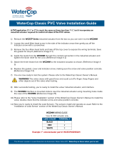
The image to the right shows a TopWorx™ unit mounted parallel to the process valve in the
closed position. The green arrow at the top shows the “normal acting” direction of travel t o open
the valve. This is the standard orientation and unless otherwise specified, your unit will be factory
set to operate in this fashion.
Installation on Actuator
Mounting
TopWorx™ has numerous mounting bracket kits available to meet your specific application,
whether rotary or linear. Consult your local distributor or factory representative for ordering
information. The illustration shows a direct Namur mount on a quarter turn valve. Refer to your
mounting kit documentation for specific mounting instructions.
Installation Notes
1. Remove the upper housing of the unit to allow access to the target cam assembly.
2. Hold the unit above the mounting surface in the orientation in which you intend to mount.
Rotate the shaft to align the tang with the actuator slot. In some cases, it may be nec es s ary t o
rotate the target cam on the shaft to allow assembly. For most units , the target c am is s ec ured
with a compression spring. Simply grasp the cam, push down, and realign the cam as required.
On some units, the target cam is secured with a snap ring. On these units, the removal of the
shaft from the base assembly will be required to change the orientation. Once removed from t he
base assembly, remove the snap ring securing the target cam and rotate as required.
3. Use caution not to allow undue axial (thrust) load on the shaft.
4. Cycle the valve a couple of times prior to final tightening of the mounting kit hardware. This
allows the shaft to self-center in the pinion slot, or coupler. Refer to the dimensions and materials
section of this document for appropriate tightening torque. Refer to the Proof Testing sect ion f or
proper safety function setup.
5. Always use sound mechanical practices when torqueing down any hardware or making
pneumatic connections. Refer to the Integrated Pneumatic Control Valves section for detailed
information on pneumatic connections.
6. This product comes shipped with plastic plugs in the conduit entries in order to protect the
internal components from debris during shipment and handling. It is the responsibility of the
receiving and/or installing personnel to provide appropriate permanent sealing devices to prevent
the intrusion of debris or moisture when stored outdoors or when installed.
7. It is the responsibility of the installer, or end user, to install this product in accordance wit h t he
National Electrical Code (NFPA 70) or any other national or regional code defining proper
practices.

5
Dimensions and Materials: TopWorx™ TXP
MATERIALS OF CONSTRUCTION
Enclosure
Cast A360 aluminum with chromate conversion coating
inside & out, epoxy coated exterior rated for 1,000 hrs salt
spray per ASTM B117
Fasteners
304 Stainless Steel standard
316 Stainless Steel optional
Shaft
304 Stainless Steel standard
316 Stainless Steel optional
Shaft Bushing
ASTM C83600 Bronze
Indicator Dome
Polycarbonate, UV F1 rated
Seals
Silicone/EPDM (Other materials available upon request)
Fastener Torque Specifications
Enclosure Housing Bolts
8 ft-lbs [10.8 N·m] +/- 10%
Indicator Dome Screws
200 in-oz [141 mN·m] +/- 10%
Bottom Mounting Holes
10 ft-lbs [13.6 N·m] +/- 10%

6
Dimensions and Materials: TopWorx™ TXP Flat Top
MATERIALS OF CONSTRUCTION
Enclosure
Cast A360 aluminum with chromate conversion coating
inside & out, epoxy coated exterior rated for 1,000 hrs salt
spray per ASTM B117
Fasteners
304 Stainless Steel standard
316 Stainless Steel optional
Shaft
304 Stainless Steel standard
316 Stainless Steel optional
Shaft Bushing
ASTM C83600 Bronze
Seals
Silicone/EPDM (Other materials available upon request)
Fastener Torque Specifications
Enclosure Housing Bolts
8 ft-lbs [10.8 N·m] +/- 10%
Bottom Mounting Holes
10 ft-lbs [13.6 N·m] +/- 10%

7
Dimensions and Materials: TopWorx™ TXS
MATERIALS OF CONSTRUCTION
Enclosure
Stainless steel. 316
Fasteners
304 Stainless Steel standard
316 Stainless Steel optional
Shaft
304 Stainless Steel standard
316 Stainless Steel optional
Shaft Bushing
316 Stainless Steel
Indicator Dome
Same as TXP Dome
Seals
Buna/EPDM (Other materials available upon request)
Fastener Torque Specifications
Enclosure Housing Bolts
8 ft-lbs [10.8 N·m] +/- 10%
Indicator Dome Screws
200 in-oz [i41 m N m] +/- 10%
Bottom Mounting Holes
10 ft-lbs [13.6 N·m] +/- 10%

8
Dimensions and Materials: TopWorx™ TXS Flat Top
MATERIALS OF CONSTRUCTION
Enclosure
Stainless steel. 316
Fasteners
304 Stainless Steel standard
316 Stainless Steel optional
Shaft
304 Stainless Steel standard
316 Stainless Steel optional
Shaft Bushing
316 Stainless Steel
Seals
Silicone/EPDM (Other materials available upon request)
Fastener Torque Specifications
Enclosure Housing Bolts
8 ft-lbs [10.8 N·m] +/- 10%
Bottom Mounting Holes
10 ft-lbs [13.6 N·m] +/- 10%

9
Dimensions and Materials: Shaft Detail
TXP/TXS NAMUR Shaft
TXP/TXS Linear Shaft

10
Sensors: Basic Function
Each TX-Series unit is equipped with 2 or 4 adjustable targets with a usable range between 45° and 90°. For normal acting applications , the targets are color
coded red for closed and green for open. The color code would be reversed for reverse acting units. After installing the unit on the actuator or valve assembly ,
the targets must be set.
Normal acting
1. Rotate the valve full CW to the closed position.
2. Twist the red target or press and move the metal target CW or CCW as required to engage the switch (refer to the specif ic switch section for testing
and confirmation information about your switch type).
3. Rotate the valve full CCW to the open position.
4. Twist the green target or press and move the metal target CW or CCW as required to engage the switch (refer to the specific switch section for
testing and confirmation information about your switch type).
Reverse acting
1. Rotate the valve full CW to the open position.
2. Twist the red target or press and move the metal target CW or CCW as required to engage the switch (refer to the specific switch section for testing
and confirmation information about your switch type).
3. Rotate the valve full CCW to the closed position.
4. Twist the green target or press and move the metal target CW or CCW as required to engage the switch (refer to the specific switch section for
testing and confirmation information about your switch type).
Normal-acting closed position
- or -
Reverse-acting open position
Normal-acting open position
- or -
Reverse-acting closed position
Setting Switches
Unlock the green and red targets. Stroke the actuator open and
closed to ensure there is no obstruction in its stroke. Once t he
actuator is at the desired position, twist the knob on the cam
until the switch is made and lock the target. The red knob is f or
closed and the green knob is for open.
Push to set targets are not required to be “Unlocked”. Stroke
the actuator open and closed to ensure there is no obstruction
in its stroke. Once the actuator is at the desired position, push
and move the target until the switch is made and release the
target.
For switching angles less than 45 degrees, or more than 90
degrees, consult factory for proper configuration.

11
Switch Option D2/D4, S2/S4: GO Switches
GO Switches are dry contact, so they consume no power to operate,
have negligible voltage drop, and have no leakage current.
Wiring Diagrams
SW 1&2
SW 3&4
D2/S2 Diagram
D4/S4 Diagram
MATERIALS OF CONSTRUCTION
OPTION D
Switch Type
GO™ Switch
Sealed
Sealed Device
Form
SPDT
Operating Temperature
40˚C to 85˚C
Electrical Rating
1A@24VDC
OPTION S
Switch Type
GO™ Switch
Sealed
Hermetic Seal
Form
SPDT
Operating Temperature
40˚C to 85˚C
Electrical Rating
3mA to
3A@24VDC or
3A@120VAC
Terminal Wire Size (D and S)
.2-2.5mm²
24-14AWG

12
Switch Option L2: GO Switches
GO Switches are dry contact, so they consume no power to operate and
have no voltage drop or leakage current.
Wiring Diagram
Repeatability
.002" (.05 mm)
Response Time
8 milliseconds
Differential
0.020 to 0.150 (0.5mm to 3.8mm)
Operating Temperature
-76°F to 221°F
(-60°C to 105°C)
Contact Material
Silver cadmium oxide,
gold flashed
Sealed
Hermetic Seal, per UL 121201 / IEC: 60079-15
Forms
SPDT, Form C
Electrical Rating
3mA to 3A@24VDC / 4A@120VAC
Target Material
Ferrous metal
Sensing Range
Approx. 1/10" (2.5 mm)
Sensing Range with
Target Magnet
3 5/8" (92mm) (max)
Also available from TopWorx™: The TopWorx™ D-Series with DPDT, Stainless Steel GO Switches.
Call Inside Sales or email info.topworx@emerson.com for more details

13
Switch Option M2/M4 or K2/K4: SPDT Mechanical Switches
When installing units with M or K switches a standard voltage ohm meter
may be used to set the target cams by looking for continuity between the
N/O and COMMON wires.
Wiring Diagram
Switch Option T2: DPDT Mechanical Switches
When installing units with T switches a standard voltage ohm meter may be
used to set the target cams by looking for continuity between the N/O and
COMMON wires.
Wiring Diagram
PRODUCT SPECIFICATIONS
Switch Type
Mechanical
Sealed
No
Circuitry
DPDT
Termination
Quick Connect
Electrical Rating
8A 125V AC or 250V AC
Conforming to Standards
UL recognized and CSA certified, meets
MIL-S-8805
Contact
Silver
Terminals
End Solder
PRODUCT SPECIFICATIONS
OPTION M
Switch Type
Mechanical
Sealed
No
Circuitry
SPDT
Termination
Quick Connect
Electrical Rating
10A@125VAC or 250VAC
Conforming to Standards
UL: 1054
Contact Resistance
15MΩmax. (initial)
Insulation Resistance
100MΩmin. (at 500V DC)
OPTION K
Switch Type
Mechanical
Sealed
No
Circuitry
SPDT
Termination
Quick Connect
Electrical Rating
10A@125VAC or 250VAC
Conforming to Standards
UL: 1054

14
Switch Options P2 or R2/R4: SPDT Reed Proximity Switches
When installing units with P or R switches a standard voltage ohm meter may be used to set the target cams by looking for continuity between the N/O and
COMMON wires.
Wiring Diagrams (R2/P2)
PRODUCT SPECIFICATIONS
P Option
Switching Voltage
VDC 120V Max
Carry Current
3 Amp Max
Power Rating
3 - 100 Watt
Contact Material
Tungsten
R Option
Switching Voltage
DC/AC 30V Max
Carry Current
0.5 Amp Max
Switching Current
0.2 Amp Max
Power Rating
3 Watt
Contact Material
Rhodium
Conforming to Standards
UL: 1054

15
Switch Option E2/E4: Inductive NAMUR Sensors
Basic inductive sensors
• 2mm sensing range
• Flush mountable
• NAMUR output
• Intrinsically safe when connected to an approved switch
isolator
Wiring Diagram: Switch Option E2
Wiring Diagram: Switch Option E4
When installing TopWorx™ products with P&F sensors,
we suggest using a commercially available switch tester
like P&F part number: ST0-03 switch tester.
PRODUCT SPECIFICATIONS
General Specifications
Switching element function
NAMUR NC
Rated operating distance
s
n
2 mm
Installation
embeddable
Output polarity
NAMUR
Assured operating distance
s
a
0 ... 1.62 mm
Reduction factor rAl
0.25
Reduction factor rCu
0.2
Reduction factor rV2A
0.7
Nominal Ratings
Nominal voltage
Uo
8 V
Switching frequency
f
0 ... 1000 Hz
Hysteresis
H
typ. %
Current consumption
Measuring plate not detected
≥3 mA
Measuring plate detected
≤1 mA
Standard Conformity
EMC in accordance with
IEC / EN 60947-5-2:2004
Standards
DIN EN 60947-5-6 (NAMUR)
Ambient Conditions
Ambient temperature
-25 ... 100 °C (248 ... 373 K)
Mechanical Specifications
Connection type Core cross-
section
130 mm, PVC cable 0.14 mm2
Housing material
PBT
Sensing face
PBT
Protection degree
IP67
General Information
Use in the hazardous area
see instruction manuals
Category
1G; 2G; 1D

16
Switch Option 12: Inductive Sensors
Wiring Diagram: Switch Option E2
Note 1: When using any model at an ambient temperature between -40°C and -25°C and a power
voltage between 30 and 32 VDC, use a load current of 100 mA max.
PRODUCT SPECIFICATIONS
Item
Standard
Switch Option 1 - M12 body
5mm sensing
Differential travel
10% max. of sensing distance
Power supply voltage
(operating voltage range)
12 ~ 24 VDC. Ripple (p~p): 10% max. (10 ~ 30 VDC)
Current consumption
(DC 3-wire)
10 mA max.
Output type
PNP
Control output
200 mA max. (32 VDC max.) [see Note 1]
Residual voltage
1.0 V max. (under load current of 200 mA with cable length of
2m)
Operation mode (with
sensing object approaching)
N/O
Protection circuit
Output reverse polarity protection, Power source circuit
reverse polarity protection, Surge suppressor, Short-circuit
protection
Ambient air temperature
Operating: -40°C to 70°C, Storage: -40°C to 85°C
(with no icing or condensation)
Temperature influence
(See note 1 below)
±10% max. of sensing distance at 23°C within temperature
range of -25°C to 70°C ±15% max. of sensing distance at
23°C within temperature range of -40°C to 70°C
Ambient humidity
Operating: 35% to 95%, Storage: 35% to 95%
Voltage influence
±1% max. of sensing distance in rated
voltage range ±15%
Insulation resistance
50 MΩ min. (at 500 VDC) between current carry parts and case
Dielectric strength
1,000 VAC at 50/60 Hz for 1 min between current carry parts
and case
Vibration resistance
10 to 55 Hz, 1.5mm double amplitude for 2 hours each in X, Y
and Z directions
Shock resistance
1,000 m/s2, 10 times each in X, Y and Z directions
Standards and listings
IEC60529: IP66, Degree of protection EN60947-5-2: EMC

17
Switch Option 42/44 or 52/54: Inductive Sensors
42 Wiring Diagram
44 Wiring Diagram
52 Wiring Diagram
54 Wiring Diagram
Switch Option 42/44 Switch Option 52/54
SUPPLY VOLTAGE
5-60 VDC
LOAD CURRENT (IL)
100 mA max.
LEAKAGE CURRENT (OFFSTATE)
0.05 mA typ., 0.1 μA at
25ºC
OUTPUT
2 Wire DC normally
open
VOLTAGE DROP AT IL (MAX.)
≤ 5 VDC
HYSTERESIS
Typ. 0.2mm
SHORT CIRCUIT AND OVERLOAD
PROTECTION
No
REVERSE POLARITY
Yes
FACE MATERIAL
Crastin
STANDARDS
IEC / EN 60947-5-
2:2004
ENVIRONMENTAL PROTECTION
IP67
AMBIENT TEMPERATURE
-14°F to +185°F
(-25.6ºC to +85ºC)
SUPPLY VOLTAGE
10-30 VDC
LOAD CURRENT (IL)
100 mA max.
LEAKAGE CURRENT (OFFSTATE)
0.05 mA typ., 0.1 μA at 25ºC
OUTPUT
PNP normally open
VOLTAGE DROP AT IL (MAX.)
≤ 3 V
HYSTERESIS
—
SHORT CIRCUIT AND
OVERLOAD
PROTECTION
Yes
REVERSE POLARITY
Yes
FACE MATERIAL
PBT
STANDARDS
EN 60947-5-2
PROTECTION DEGREE
IP67
AMBIENT TEMPERATURE
-14ºF to +158ºF
(-25.6ºC to +70ºC)

18
Switch Option 0X: 4-20mA Position Transmitter
Wiring Diagram
ELECTRICAL DATA
Voltage Input Range
8.5 - 34 Volts DC
Standard Output Signal
Two wire 4-20mA with out of range indication
Input Polarity
Bi-Directional
Primary Usage
The 2-wire 4-20mA transmitter will generate a nominal 4
– 20mA output for full-range actuation of the valve. The
generating signals below 4mA and above 20mA if the
position sensor indicates an out of range value.
Rotation
Any rotation range between 20 and 320 degrees.
Factory set for 20 to 180 degree operation in
counterclockwise rotation to open, and 20 to 90 degree
operation in clockwise rotation to open applications.
Modes
Optional linear and rotary modes
Linearity
+/-1%*
Repeatability
0.3%*
Hysteresis
0.5%*
Temperature
-40ºC to 85ºC
*Indicated linearity, repeatability and hysteresis is for the device only. Installed
specifications will depend on the total mechanical and electrical system’s capability.

19
Switch Option 0X: 4-20mA Position Transmitter
Operation of the 4-20mA Current Position Transmitter
During run mode, the 4-20mA position transmitter will output 4-20mA for valve positions between and including the set points. In rotary mode, the module has an
optional over or under travel correction if the valve position exceeds the high or low set point by +/ -3%. In other words, the output will be 4mA for +/-3% over and under
travel on the low end, and 20mA for +/-3% over and under travel on the high end. If the valve position exceeds 3% of over travel, then values below 4mA or above
20mA will be output. The other user-selectable option is to calibrate the device without the over and under travel capability (Linear Mode.) See the calibration flow chart
in this document for additional information.

Switch Option 0X: 4-20mA Position Transmitter
20
Troubleshooting
Error Code and Problem Table
Problem Probable Cause/Solution
Transmitter Module has no current output
If the LED on the Transmitter Module is not lit
- Loose or shorted signal connection (fix connection)
- Controller Board not responding (Replace Transmitter Module)
If the LED on the Circuit Board is lit
- Potentiometer is disengaged from shaft (must be returned for repair)
- Defective controller board (Replace Transmitter Module)
Transmitter does not output 4 or 20mA (+/-
1%) at desired end of travel
Unit not calibrated (calibrate)
Unit is calibrated (recalibrate - if still fails, replace board)
Output is not linear or does not track valve
position or rotation
Input signal is not linear
- Linkage or drive mechanism is introducing non-linearity
- Unit is not calibrated (calibrate)
Error Code 4-3
Start position is too low or in the dead-band position.
Error Code 4-4
Start Position is too high
Error Code 4-5
Start and stop positions are less than 20º, increase valve
rotation between start and stop positions to greater than 20º.
Error Code 4-6
Rotation has exceeded the 320º limit. Decrease valve rotation
between start and stop positions to less than 320º.
Error Code 4-7
Calibration rotation was in the wrong direction or the
potentiometer passed through the dead-band position.
Error Code 4-1
Internal Error has occurred. Recalibrate, if error continues, replace module.
LED Flash Code Diagram
Flash Codes
(first count – second count) Interpretations
0-0
Calibrated
3-1
Counter-Clockwise Calibration; Waiting to calibrate the 4mA position; Rotary Mode
3-2
Clockwise Calibration; Waiting to calibrate the 4mA position; Rotary Mode
3-3
Waiting for 20mA Full Open Setting Button Press
4-1
Calibration Required
4-3
Calibration Start Value is Too Low
4-4
Calibration Start Value is Too High
4-5
End Value is Too Close to Start Value
4-6
Maximum Rotation Exceeded
4-7
Wrong Direction of Rotation
5-1
Counter-Clockwise Calibration; Waiting to calibrate the 4mA position; Linear Mode
5-2
Clockwise Calibration; Waiting to calibrate the 4mA position; Linear Mode
During calibration, make sure the potentiometer is not rotating through its deadband area. The
red dot located on the potentiometer should not rotate through the area marked with red during
the full rotation of the valve. If it does, reposition the shaft.
DEADBAND
INDICATION
/