VALIN Go Switch User manual

Type
User manual

VALIN Go Switch is a versatile and reliable proximity switch designed to detect the presence or absence of metal objects. With its rugged construction and adaptability to various applications, it provides precise and efficient solutions for industrial automation needs. The switch features:

  • Sensing range up to 2 inches (50 mm) for ferrous targets and 1 inch (25 mm) for non-ferrous targets.
  • Easy installation with flexible mounting options and adjustable sensing distance.
  • Compatibility with AC and DC power sources, offering greater flexibility in electrical systems.
  • Durable construction with IP67 rating, ensuring protection against dust and water ingress, suitable for harsh industrial environments.
IOM TopWorx engineers are happy to provide technical assistance on GOTM Switch products. However, it is the
customer's responsibility to determine the safety and suitability of the product in their application. It is also the
customer's responsibility to install the switch using the current electrical codes in their region. 10 & 20 Series
Incorrect Correct
TM
Caution- Switch Damage
Switch must be installed according to local electrical codes.
Wiring connections must be properly secured.
For two-circuit switches, contacts must be connected to the same polarity in order to
minimize the possibility of a line-to-line short.
In damp environments, use a certified cable gland or a similar moisture barrier to
prevent water/condensation from entering conduit hub.
Danger- Improper Use
All switches must be installed per the certification requirements.
Mounting tips for standard and latching switch
Determine the desired operating point.
Determine location of the sensing area on the GO™ Switch.
Position the switch and target in a position that ensures the target comes within the
switches sensing area.
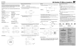
In Figure 1, the target has been posi-
tioned to stop on the outside edge of
the sensing envelope. This is a margin-
al condition for long term reliable
operation.
In Figure 2, the target has been posi-
tioned to stop well within the sensing
envelope which will assure long reliable
operation.
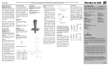
Ferrous target needs to be at least one cubic inch in size. If the target is less than one
cubic inch in size, it may significantly reduce operational effectiveness or the target might
not be detected by the switch.
Figure 1 Figure 2
Target Target
Sensing Range
Sensing Range
Sensing Range Sensing Range
Mild
Steel
In Figure 3, the ferrous target is too small
to be detected reliably over the long term.
In Figure 4, the target has sufficient size
and mass for long term reliable operation.
Switch may be mounted in any position.
Figure 3 Figure 4
Side by side on non-ferrous bracket
(Figure 5 and 6).
Figure 5
Sensing Area Sensing Area
Figure 6
Switch mounted on non-magnetic materials
Recommended for the best results
a). Keep all ferrous materials at least 1” from switch.
b). Steel placed outside the switches sensing area will not affect functioning.
It is not recommended that switches are mounted on ferrous metal, due to the reduction
in sensing distance.
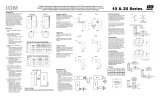
Activate/Deactivate the switch
a). Switch with standard contacts - has sensing area on one side of the switch (A). To
activate, the ferrous or magnetic target must fully enter the sensing area of the switch
(Figure 7). To deactivate the target must move fully outside the sensing area, equal or
greater than the reset distance in Table.
Sensing Range Sensing Range Sensing Range
Figure 7 Figure 8 Figure 9
Switch is activated Switch is deactivated Switch is activated again
A
Target A
Target
A
Target
To activate the contacts on side A (see Figure 10), the target must fully enter sensing
area A of the switch (see sensing ranges in Table x). To deactivate the contacts on side
A and activate on side B, the target must move fully outside of sensing area A and anoth-
er target fully enter sensing area B (Figure 11). To reactivate the contacts on side A, the
target must fully exit sensing area B and the target must fully re-enter sensing area A
(Figure 13).
Target Target Target
Sensing Range Sensing Range Sensing Range
Figure 10 Figure 11 Figure 12
Sensing Range
Ferrous Target
Steel bar target 1/2” (13mm)
x 1” (25mm) x4” (102mm).
Factory standards ferrous
target used to establish
sensing and reset distance.
(Figure 14).
A-Sensing
B-Reset
Sensing range including ferrous target and magnets.
Standard & Latching Extended Sensing (available only for 10
Table 1 Table 2
Sealing Switches
Figure 14 Figure 15
Conduit
Water
Attachment of Conduit or Cable
Figure 16 Figure 17
Wiring Information
AC
Volts 120 240 480
Amps 10 5 2.5
Volts 24 48 120
DC
Amps 3 1 0.5
Table 3
All GO Switches are dry contact switches, meaning that they have no voltage
drop when closed, nor do they have any leakage current when open. For multi-
unit installation, switches may be wired in series or in parallel.
In Figure 14, the conduit system is filled with water and is leaking inside the
switch. Over a period of time, this may cause the switch to fail prematurely.
In Figure 15, the termination of the switch may be fitted with a certified thread-
ed cable entry device (user supplied) in accordance with the manufacturer's
instructions to prevent water intrusion resulting in premature switch failure. A
drip loop with provision for water to escape has also been installed.
Ratings
If the switch is mounted on a moving part, be sure that the flexible conduit is
long enough to allow for movement, and positioned to eliminate binding or
pulling. (Figure 16). In damp applications, use a certified cable gland or a
similar moisture barrier to prevent water/condensation from entering the
conduit hub. (Figure 17).
Sensing Area
A
B
Figure 13
Buy: www.ValinOnline.com | Phone 844-385-3099 | Email: [email protected]
IOM 10 & 20 Series
Visit www.topworx.com for
comprehensive information on our company, capabilities, and
products – including model numbers, data sheets, specifica-
tions, dimensions, and certifications.
www.topworx.com
© 2013-2016 TopWorx, All rights reserved. TopWorx™, and GO™ Switch are
all trademarks of TopWorx™. The Emerson logo is a trademark and a service
mark of Emerson Electric. Co. © 2013-2016 Emerson Electric Company. All other
marks are the property of their respective owners. Information herein – including
product specifications – is subject to change without notice.
GLOBAL SUPPORT OFFICES
Americas
3300 Fern Valley Road
Louisville, Kentucky 40213 USA
+1 502 969 8000
S-K025 R11
Grounding
Depending on certification requirements, GO
Switches may be supplied with or without an
integral ground wire. If supplied without a
ground wire, installer must ensure proper
ground connection to the enclosure.
Europe
Horsfield Way
Bredbury Industrial Estate
Stockport SK6 2SU
United Kingdom
+44 0 161 406 5155
Africa
24 Angus Crescent
Longmeadow Business Estate East
Modderfontein
Gauteng
South Africa
27 011 441 3700
Middle East
P.O. Box 17033
Jebel Ali Free Zone
Dubai 17033
United Arab Emirates
971 4 811 8283
Asia-Pacific
1 Pandan Crescent
Singapore 128461
+65 6891 7550
GO™ Switch Wiring Diagrams
Ex ia IIC T6 Ga (-40oC to +50oC)
Ex ia IIIC T85°C Da
Baseefa 12ATEX0187X
IECEx BAS
0518 II 1 GD
Ex ia IIC T4 Ga (-40oC to +100oC)
Ex ia IIIC T135°C Da
Baseefa 12ATEX0187X
IECEx BAS 12.0106X
0518 II 1 GD
Marking
TM
Form “A”
Normally Open
Typ. Alarm or Limit
Warning Hookup
Load
N/O
COM AC or DC
Form “Z”
Normally Closed
Normally Open
Double Make
Double Break
Wire same
polarity only
AC or DC
Load
Load
N/O
N/O
N/C
N/C
0518 II 1 GD
Ex ia IIC T3 Ga (-40oC to 150oC)
Ex ia IIIC T85°C Da
Baseefa 12ATEX0187X
IECEx BAS 12.0106X
Ex de IIC T6 Gb, Ex tb IIIC T85°C Db, IP66/68
Tamb = -40°C to +60°C
Baseefa12ATEX0160X
IECEx BAS 12.0098X
30V AC/DC @ 0.25A FOR SPDT SWITCHES
0518 II 2 GD
Special Conditions for Intrinsic Safety
Both contacts of the Double Throw and the separate poles of the Double Pole switch, within one switch must form part of the same
intrinsically safe circuit.
The proximity switches do not require a connection to earth for safety purposes, but an earth connection is provided which is directly
connected to the metallic enclosure. Normally an intrinsically safe circuit may be earthed at one point only. If the earth connection is
used, the implication of this must be fully considered in any installation. I.e. by use of a galvanically isolated interface.
The terminal block variants of the equipment are fitted with a non-metallic cover that constitutes a potential electrostatic hazard and
must only be cleaned with a damp cloth.
The switch must be supplied from a certified Ex ia IIC Intrinsically safe source.
The flying leads must be terminated in a manner suitable for the zone of installation.
Terminal Block Wiring For Flameproof And Increased Safety
1.External earth bonding can be achieved via the mounting fixings. These fixings should be in stainless steel or an alternative non-
ferrous metal in order to minimize both corrosion and magnetic interference of the switch function. The connection shall made in such a
manner as to prevent loosening and twisting (e.g. with shaped lugs/nuts and locking washers).
2. Suitably certified cable entry devices shall be installed in accordance with IEC60079-14 and must maintain the ingress protection (IP)
rating of the enclosure. The cable entry device thread shall not protrude within the enclosure body (i.e. shall maintain the clearance to
the terminals).
3. Only one single or multiple strand conductor of size 16 to 18 AWG (1.3 to 0.8mm2) is to be accommodated in
each terminal. The insulation of each conductor shall extend to within 1 mm of the terminal clamping plate. Con-
nection lugs and/or ferrules are not permitted.
Wiring must be 16 to 18 gauge and rated for the electrical load marked on the switch with a service temperature of
at least 80°C.
Wire terminal screws, (4) #8-32X5/16” stainless with annular ring, must be tightened down to 2.8 N-m [25 lb-in].
Cover plate must be tightened down to terminal block to a value of 1.7 N-m [15 lb-in].
EU Declaration of Conformity
The products described herein, conform
to the provisions of the following Union
Directives, including the latest amend-
ments:
Low Voltage Directive (2006/95/EC)
EMC Directive (2004/108/EC)
Machinery Directive (2006/42/EC)
ATEX Directive (2014/34/EU).
Form “C”
Typ. Dual Load
Hookup
N/
Loa
Loa
COM
N/C
AC or DC
COM
AC or DC
Form “B”
Normally Closed
Typ. Over travel or Limit
Hook Up
Load
N/C
Buy: www.ValinOnline.com | Phone 844-385-3099 | Email: [email protected]
  • Page 1 1
  • Page 2 2

VALIN Go Switch User manual

Type
User manual

VALIN Go Switch is a versatile and reliable proximity switch designed to detect the presence or absence of metal objects. With its rugged construction and adaptability to various applications, it provides precise and efficient solutions for industrial automation needs. The switch features:

  • Sensing range up to 2 inches (50 mm) for ferrous targets and 1 inch (25 mm) for non-ferrous targets.
  • Easy installation with flexible mounting options and adjustable sensing distance.
  • Compatibility with AC and DC power sources, offering greater flexibility in electrical systems.
  • Durable construction with IP67 rating, ensuring protection against dust and water ingress, suitable for harsh industrial environments.

Ask a question and I''ll find the answer in the document

Finding information in a document is now easier with AI