Page is loading ...

IOM TopWorx engineers are happy to provide technical assistance on GO™ Switch products. However, it is the
customer's responsibility to determine the safety and suitability of the product in their application. It is also the
customer's responsibility to install the switch using the current electrical codes in their region. 80 Series
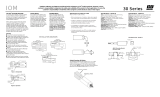
The GO™ Switch Proximity
Principle
Single-magnet 80 Series GO
Switches are designed for use
with two independent circuits. A
ferrous armature is positioned off
-center, creating dominance and
placing the contacts for both
circuits in a Normally Closed
(N/C) position (Figure 1).
When a ferrous actuator enters
the sensing area of the switch
(Figure 2), it deflects magnetic
flux from the N/C side of the
armature and the Normally Open
(N/O) side becomes dominant.
The armature then snaps to its
alternate position, closing the N/
O contacts. When the actuator is
removed, the magnet again
becomes dominant on the N/C
side and the armature returns to
its N/C position.
SPECIFICATIONS - DPDT
Contacts: Double Pole, Double
Throw, 2 Form C., Silver cadmi-
um oxide, gold flashed
Rating: 1250 watts @ 120, 240,
480 or 600 VAC. Maximum cycle
rate of 10 cycles per minute
resistive load at 10 amps.
Housing: Environmentally
sealed 316L stainless steel or
standard enclosure
Conduit Outlet:1/2" -14NPT
Repeatability: 0.002" (0.05mm)
typical
Sensing Distance: Approx.
1/4" (7mm) end sensing. (NOTE:
Sensing distance may be affect-
ed by surrounding ferrous materi-
als and actuator size)
Differential: Approx.1/4" (72mm)
Response time: 8 milliseconds
Temperature Rating: -40oF.
(-40oC) to 221oF (105oC)
Mounting
■Determine the desired operat-
ing point.
■Locate switch and/or actuator
to assure that actuator comes
well within switch’s sensing
area.
■Use a ferrous actuator of
sufficient size.
■Recommended sensing is
one half the published sens-
ing range for trouble free
operation with a repeatable
target. If target sensing area
needed is greater, there are
multiple target magnets avail-
able from TopWorx to extend
the range of the switch.
■Avoid contact between switch
and actuator, which may
damage switch.
■For best results, mount switch
on non-ferrous materials.
■Steel placed outside the
switch’s differential area will
not affect functionality.
■We do not recommend that
GO Switches be mounted to
ferrous metal. If a ferrous
mount is the only option
consult factory. The switch
must be centered on the
bracket to avoid latching and
the maximum sensing dis-
tance will be reduced by
approximately 50%. A target
magnet is highly suggested in
that case.
■Ferrous brackets or surround-
ing ferrous metal should NOT
be applied to the top of the
switch above the sensing
area...Latching may occur.
■Switch must be centered on
ferrous mounting bracket so
that effects on the magnet are
uniform.
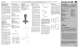
Attachment of Conduit or Cable
Attach conduit or cable correctly.
– When using long runs of conduit or cable, place supports close to
the switch to avoid pulling switch out of position.
– If switch is mounted on a moving part, be sure flexible conduit is
long enough to allow for movement, and positioned to eliminate
binding or pulling.
– For installation in hazardous locations, check local electrical codes.
– All conduit connected electrical devices, including GO Switches,
must be sealed against water ingression through the conduit sys-
tem. In figure 1, something common has occurred, the conduit
system has filled with water. Over a period of time this may cause
the switch to fail prematurely. In figure 2, the termination of the
switch has been carefully filled with electronics grade RTV to pre-
vent water ingression and to prevent premature switch failure.
A drip loop with provision for water to escape has also been in-
stalled.
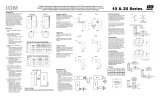
All GO Switches are "pure"
contact switches, meaning
they have no voltage drop
when closed, nor do they
have any leakage current
when open. For multi-unit
installation, switches may be
wired in series or parallel, as
shown.
Dual Form C
DPDT
Activated
Inactivated
Target
Sensing Area
Armature
Standard GO™ Switch
Actuators
The part to be sensed can ap-
proach or pass across the sens-
ing area from any direction. This
permits unlimited over-travel and
a wide variety of operating condi-
tions.
CAUTION: To assure optimum
switch operation, the actuator
speed should exceed 2 FPS
(feet per second).
Switch Sensing
Target should be either ferrous
metal the size of the sensing
face and 1/4" thick or a TopWorx
Target Magnet. Maximum sens-
ing with the recommended fer-
rous target is 5/16" . TopWorx
recommends that the target be
set at 50% of that distance if
possible, to compensate for
actuator wear and repeatability
over time. Target magnets are
available from TopWorx to ex-
tend the sensing range of the
switch.
NOTE: Actuator size effects
sensing distance.
■Contact Chamber is potted to resist contaminants. Please see notes on conduit
installation. Optional connectors available for excessive moisture and submersed
conditions.
■Multiple termination options: Lead wires, Cable, Quick Disconnects
TM
GO™ Switch
Hook-up Diagrams
EU Declaration of Conformity
The products described herein, conform to the provisions of the following Union Directives, including the latest amendments:
Low Voltage Directive (2014/35/EU)
EMD Directive (2014/30/EU)
ATEX Directive (2014/34/EU)
When solid state switches are
placed in parallel, there is about
100 microamps leakage through
each switch. If ten solid state
switches were wired in parallel, the
total leakage current would be 1000
microamps or one milliamp - suffi-
cient current to indicate an "ON"
condition to a programmable logic
controller (PLC).
Any number of GO Switches may
be wired in parallel, with no cur-
rent leakage and without drawing
operating current. (Except 7L -
approx. 5V drop)
Any number of GO Switches may
be wired in series, without voltage
drop. By contrast, solid state
switches have about two volts drop
across the switch when operated.
In a 12 volt solid state system with
four switches in series, 8 volts is
dropped across the switches. Only
4V is left to operate the load. When
using GO Switches, 12V is still
available to operate the load.
(Except 7L - approx. 5V drop)
Parallel Wiring
NOTE: Occasionally the 80 Series
DPDT is used for its end sensing,
when only a SPDT switch is re-
quired. If this is the case in your
advantage to parallel the lead wires
(red to red/white stripe, blue to
blue/white stripe and black to
black/white stripe, essentially con-
verting a DPDT switch to a SPDT
configuration) so that both individu-
al circuits see the same load and
therefore wear equally to give long
contact life and the reliable service
you expect with GO™ Switch.
Series Wiring

IOM 80 Series
Visit www.topworx.com for
comprehensive information on our
company, capabilities, and products –
including model numbers, data sheets,
specifications, dimensions, and
certifications.
www.topworx.com
The Emerson logo is a trademark and service mark of Emerson Electric Co. ©2016 Emerson Electric Co. ©2016 TopWorx, All rights reserved. TopWorx™ and
GO™ Switch are all trademarks of TopWorx. All other marks are the property of their respective owners. Information herein – including product specifications –
is subject to change without notice.
S-K030 R9
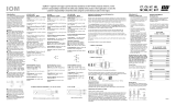
SENSING
AREA
1.5"
38mm
1.5"
38mm
.206" DIA
MTG HOLES
1/2"-14 NPT
Conduit outlet
.875"
22mm
.31"
8mm
3.12"
79mm
4.88"
124mm
1.5"
38mm
1.5"
38mm
SENSING
AREA
.875"
22mm
3.12"
79mm
.206" DIA
MTG HOLES
.31"
8mm
4.31"
109mm
.45"
12mm
1/2"-14 NPT
Conduit outlet
1" SQ hub
3.66"
93mm
Americas
TopWorx
3300 Fern Valley Road
Louisville, Kentucky 40213
USA
+1 502 969 8000
Asia-Pacific
1 Pandan Crescent
Singapore 128461
+65 6891 7550
Middle East
P.O. Box 17033
Jebel Ali Free Zone
Dubai 17033
United Arab Emirates
+971 4 811 8283
Europe
Horsfield Way
Bredbury Industrial Estate
Stockport SK6 2SU
United Kingdom
+44 0 161 406 5155
Africa
24 Angus Crescent
Longmeadow Business Estate
East
Modderfontein
Gauteng
South Africa
+27 011 451 3700
GLOBAL SUPPORT OFFICES
TM
DMD 4 Pin M12 Connector
External ground must be used with
120VAC and voltages greater then
60VDC when using the DMD
connector
/