Page 5
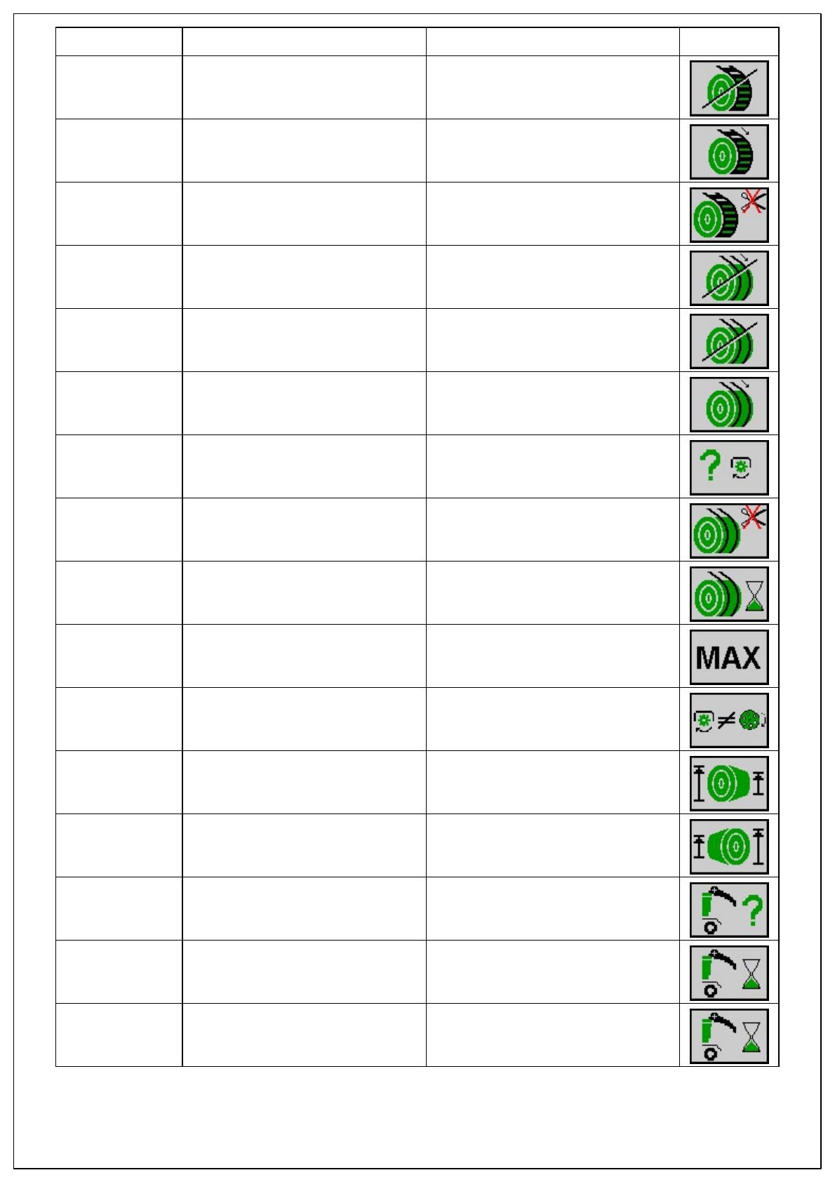
Error number Error text Description Figure
KMC-522026-7 Tying net stopped - Logic fault
mechanics
The wrapping and tying material stops
after a certain time when tying is
activated.
KMC-522027-7 Tying net is being pulled - Logic fault
mechanics
The wrapping and tying material is
being pulled from the bale even though
tying has not started.
KMC-522028-7 Tying net not cut off - Logic fault
mechanics
The wrapping and tying material has
not been cut off.
KMC-522029-7 Tying twine not pulled - Logic fault
mechanics
The wrapping and tying material was
not received by/pulled from the bale
when tying is activated.
KMC-522030-7 Tying twine stopped - Logic fault
mechanics
The wrapping and tying material stops
after a certain time when tying is
activated.
KMC-522031-7 Tying twine is being pulled - Logic
fault mechanics
The wrapping and tying material is
being pulled from the bale even though
tying has not started.
KMC-522032-18 Feed roller below minimum speed -
Lower limit value below minimum
The feed roller is below the minimum
speed when the wrapping and tying
material is pulled.
KMC-522033-7 Tying twine not cut off - Logic fault
mechanics
The wrapping and tying material has
not been cut off.
KMC-522034-7 Tying twine Timeout - Logic fault
mechanics
The twine arms could not be moved
within the stipulated time into the
required position.
KMC-522035-16 Maximum filling exceeded - Upper
limit value exceeded
The bale chamber has been filled
above the maximum.
KMC-522038-18 Slip of bale formation conveyor -
Lower limit value below minimum
The setpoint speed of the bale
formation conveyor of the bale
chamber was below the minimum.
KMC-522040-16 Left bale conical - Upper limit value
exceeded
The filling between the left and right
sides of the bale differs too much, too
large on the left.
KMC-522041-16 Right bale conical - Upper limit value
exceeded
The filling between the left and right
sides of the bale differs too much, too
large on the right.
KMC-522044-7 Position of tailgate unclear - Logic
fault mechanics
The position of the tailgate could not
be determined.
KMC-522045-7 Open tailgate Timeout - Logic fault
mechanics
The tailgate could not be opened within
the stipulated time.
KMC-522046-7 Close tailgate Timeout - Logic fault
mechanics
The tailgate could not be closed within
the stipulated time.


