Page is loading ...

InstallatIon sheet
1121 PIR Motion Detector
Description
The 1121 PIR (Passive Infrared) Motion Detector is a wireless, low current sensor that can be used in a variety of
motion detector applications. With a built-in tamper switch and switch-selectable high/low sensitivity and pet
immunity, the 1121 is very exible. For added convenience, the 1121 is designed to mount directly on the wall or
with the optional corner/ceiling mounting bracket.
Features
• Low current technology
• Low battery reporting capability
• Two Minute Walk test for testing coverage
• Calibration free height installation from 4.9 to 8.2 feet high
• Pet immunity selectable from 33 lbs. up to 60 lbs.
• Auto-Power Save (APS) mode
• Sensitivity adjustment
Compatibility
All 1100 Series Wireless Receivers and Panels
What is Included
The 1121 PIR Motion Detector includes the following:
• One PIR detector with DMP wireless transmitter
• One CR123A battery
• Zone name and number label
• Serial number label
• One optional corner/ceiling mounting bracket with hardware
Installation
For your convenience, an additional pre-printed serial number label is included. Prior to installing the device, record
the serial number or place the pre-printed serial number label on the panel programming sheet. This number is
required during programming. As needed, use the zone name and number label to identify a specic transmitter.
Programming the PIR in the Panel
Refer to the XR500 Series Programming Guide (LT-0679), the XR100 Series Programming Guide (LT-0896), XT30/XT50
Series Programming Guide (LT-0981) or the XTL Programming Guide (LT-1108) as needed. Program the device as a
zone in Zone Information during panel programming. At the Serial Number: prompt, enter the eight-digit serial
number. Continue to program the zone as directed in the panel programming guide.
Note: When a receiver is installed, powered up, or the panel is reset, the supervision time for transmitters is reset.
If the receiver has been powered down for more than one hour, wireless transmitters may take up to an additional
hour to send a supervision message unless tripped, tampered, or powered up. This operation extends battery life for
transmitters. A missing message may display on the keypad until the transmitter sends a supervision message.
Selecting the Best Location (LED Survey Operation)
The PIR transmitter provides a survey capability to allow one person to conrm transmitter communication with
the receiver while the cover is removed. Refer to Figure 1 to remove the PIR front cover. The PIR transmitter
PCB Red Survey LED turns on whenever data is sent to the receiver then immediately turns off when the receiver
acknowledgement is received. Pressing the PIR tamper switch is a convenient way to send data to the receiver to
conrm operation. The PIR circuit board LED lights to indicate motion and the Survey LED briey lights to conrm
operation. See Figure 3 for LED locations. See Installing or Replacing Batteries.
When the transmitter does not receive an acknowledgement from the receiver, the transmitter Survey LED remains
on for about 8 seconds to let you know communication is not established. Relocate the transmitter or receiver until
the Survey LED immediately turns off indicating the transmitter and receiver are communicating
properly. If the transmitter is not programmed into the panel, it does not operate properly.
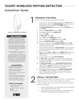
Figure 1: Remove the 1121 Cover
Unscrew the
holding screw
and gently lift
the cover.

Digital Monitoring Products 1121 PIR Installation Sheet
2
Mounting Location Considerations
Mount the unit:
• On a rigid vibration-free surface
• So the expected intruder movement is across the
detection pattern elds, see Figure 2
Do not locate the unit:
• Facing areas that may change temperature
rapidly
• In any area containing excessive metallic surfaces
• Where it may be exposed to false alarm sources
such as: direct sunlight, heat sources (heater,
radiators, etc.) in the eld of view or strong air
drafts (fans, air conditioner, etc.)
Setting the Sensitivity and Range Switches
Use the switches and dial located on the unit PCB to set sensitivity and
pet immunity as shown in Figure 3. Use the following to determine the
appropriate switch settings for an application.
Pulse Width Sensitivity Adjustment
Position 1 is for normal operating conditions and operation.
Position AUTO is used for harsh environment or locations with air drafts.
Pet Immunity Adjustment
Position 33 lbs is for locations with pets up to 33 lbs in weight.
Position 60 lbs is used for locations with pets between 33 lbs and up to 60
lbs in weight.
Auto Power Save (APS) Feature
In order to extend the battery life, the 1121 is equipped with a two-minute
sleep timer that is restarted on every motion detection. This means the
unit will awaken after two minutes with no motion detected. This allows
the 1121 to be used for busy lobbies or areas that have lots of trafc during
the disarmed period.
Testing
The test push button is located below the tamper switch. Use this button
to activate the detector Walk Test and RF transmission test modes. Perform
the steps following each test option to verify operation. Refer to Figure
3 to identify the test push button location. Before performing any of the
tests, ensure the 1121 PIR is currently programmed in the panel.
Walk Test
1. Lift the unit front cover.
2. Press the test push button for one second. The LED will ash three times indicating it is in Walk Test mode. This
activates the device for two minutes in Walk Test mode. Replace the front cover. At the end of the Walk Test
mode, the LED will ash six times.
3. Walk test the unit to verify the PIR coverage.
Note: This is for IR detection only and does not send an RF transmission.
Alarm Transmission Test
1. Lift the unit front cover.
2. Press the test push button for more than four seconds. The LED will ash three times and then stay lit for one
second. This immediately activates the alarm RF transmission. Replace the front cover.
3. To check this function, verify that the keypad display indicates a signal received from the detector. The
detector sends 11 transmissions to the control panel during the one minute test period.
Tamper Transmission Test
1. Lift the unit front cover to fault the tamper and initiate a tamper trouble message.
2. Verify that the keypad display indicates a tamper message. Replace the front cover.
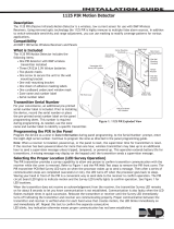
Figure 3: 1121 PIR Circuit Layout
+–
+
+
AUTO1 33 LB 60 LB
PULSE PET
Q1
DMP WIRELESS PIR
P/N 3201504
Tamper
Test
Pushbutton
Pulse Width
Switch
Pyrosensor
Sensitivity
Dial
Pet Immunity
Switch
Battery
D1 LED
(Survey)
Mounting
Screw
+-
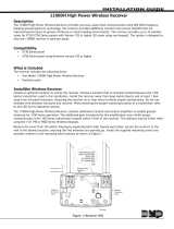
Figure 2: Detection Pattern
Alarm
Alarm with
Pet Immunity
No Alarm with
Pet Immunity

1121 PIR Installation Sheet Digital Monitoring Products
3
Mounting the Unit
Prior to permanently mounting the 1121 PIR, check that the PIR to control panel communication is working. See the
Unit Testing section.
1. Use a Phillips head screwdriver to unscrew the holding screw at the lower end of the 1121 case, gently raise
the front cover, and slide the cover out of the closing pins. Refer to Figure 1.
2. Use a Phillips head screwdriver to loosen the mounting screw located on the PIR printed circuit board (PCB) and
slide the PCB out of the unit. See Figure 3 for the mounting screw location.
3. Select and open the appropriate knockout mounting holes on the mounting bracket for the best mounting
location. See Figure 4.
4. Use screws and wall anchors, if necessary, to mount the detector base to the wall in a corner.
5. Reinstall the PCB back into the unit. Tighten the PCB mounting screw to secure it into place.
6. Install the battery. See Installing or Replacing Batteries later in this document.
7. Insert the cover back into the appropriate closing pins and tighten the holding screw back into place.
Optional Corner/Ceiling Mounting Bracket
The 1121 PIR can optionally be attached to a corner/ceiling mounting bracket. The bracket can be mounted to the
ceiling or a wall location. Refer to Mounting the Unit, Figure 1 and Figure 5 as needed.
1. Open the PIR and remove the battery and PCB.
2. Open the required bracket mounting knockout holes.
3. Reinstall the PCB and the battery.
4. Install the bracket on the wall or ceiling using the included screws.
5. Slide the assembled 1121 PIR onto the mounting bracket.
Installing or Replacing Batteries
Note: If the battery reaches the factory preset low level, a Low Battery signal is sent to the panel. The 1121 PIR
remains operational for approximately 30 days to allow adequate time to replace the battery.
Observe polarity when installing the battery. Use only 3.0V lithium batteries, DMP Model CR123, or the equivalent
battery from a local retail outlet.
Note: When setting up a wireless system, it is recommended to program zones and connect the receiver before
installing batteries in the transmitters.
1. If necessary, remove from the wall mounting bracket. See Optional Corner/Ceiling Mounting Bracket or
Mounting the Unit.
2. Remove the front cover. See Figure 1.
3. Remove the battery (if installed) before installing a new battery.
Caution: Risk of re, explosion, and burns. Do not recharge, disassemble, heat above 212°F (100°C), or
incinerate. Properly dispose of unused batteries.
4. Observe polarity and insert the lithium battery into the battery holder where indicated in Figure 3.
Battery Life Expectancy
Typical battery life expectancy for DMP Model 1121 wireless PIR is three years. DMP wireless equipment uses
two-way communication to extend battery life.
Figure 4: Knockout Hole Locations
A. Not in use.
B. Use for at wall
mounting.
C. Corner mounting -
use all four holes.
Sharp left or right
angle mounting -
use one top hole
and one bottom
hole.
D. For bracket
mounting.
A A
B B
C C
D
A
C C
B B
Bracket
Installation
Wall Mount Installation
Ceiling Mount Installation
Figure 5: Optional Bracket Mounting

LT-0699 © 2015 Digital Monitoring Products, Inc.
15125
800-641-4282
www.dmp.com 2500 North Partnership Boulevard
The following situation can extend battery life expectancy:
• Extend transmitter supervision time in panel programming.
• Infrequent transmission trips, such as a low trafc area where messages are rarely sent.
The following situations can reduce battery life expectancy:
• If a receiver is unplugged, too far away, or not installed.
Note: Transmitters continue to send supervision messages until a receiver returns an acknowledgement.
After an hour the transmitter only attempts a supervision message every 60 minutes.
• Frequent transmissions, such as constant motion where messages are sent every time the movement is
detected.
Note: To compensate for frequent motion, the 1121 PIR automatically rests until no motion is detected for two
minutes. After two minutes of no activity, the 1121 PIR is ready to respond to any motion detected. Because of
this operation, do not program a wireless PIR for cross zone operation unless other zones are also programmed
to provide cross zone operation.
• When installed in extreme hot or cold environments.
Maintenance
When installed and used properly, the unit provides years of service with minimal maintenance. To ensure proper
operation, you should perform unit testing annually as described above. Clean the cover and optional bracket with a
water dampened cloth as needed to keep it free of dust and dirt. Always test the unit after cleaning.
FCC Information
This device complies with Part 15 of the FCC Rules. Operation is subject to the following two conditions:
(1) This device may not cause harmful interference, and
(2) this device must accept any interference received, including interference that may cause undesired operation.
Changes or modications made by the user and not expressly approved by the party responsible for compliance could void the
user’s authority to operate the equipment.
The antenna used for this transmitter must be installed to provide a separation distance of at least 20 cm from all persons. It
must not be co-located or operated in conjunction with any other antenna or transmitter.
Note: This equipment has been tested and found to comply with the limits for a Class B digital device, pursuant to part 15 of the
FCC Rules. These limits are designed to provide reasonable protection against harmful interference in a residential installation.
This equipment generates, uses and can radiate radio frequency energy and, if not installed and used in accordance with the
instructions, may cause harmful interference to radio communications. However, there is no guarantee that interference will not
occur in a particular installation. If this equipment does cause harmful interference to radio or television reception, which can be
determined by turning the equipment off and on, the user is encouraged to try to correct the interference by one or more of the
following measures:
- Reorient or relocate the receiving antenna.
- Increase the separation between the equipment and receiver.
- Connect the equipment into an outlet on a circuit different from that to which the receiver is connected.
- Consult the dealer or an experienced radio/TV technician for help.
Specications
Battery
Life Expectancy 3 years (normal operation)
Type 3.0V Lithium CR-123
See Battery Life Expectancy for details.
Transmit condition Alarm, Low Battery
Detection
Range 90° 50 x 50 feet
Speed 1 to 5 feet/second
Mounting height 4.9 to 8.2 feet
Frequency Range 903-927 MHz
Dimensions 4.8” H X 2.5” W X 1.45” D
Color White
Patents
U. S. Patent No. 7,239,236
Certications
FCC Part 15 Registration ID CCKPC0088
/