Page is loading ...

Outdoor Sun Shade
ASSEMBLY, INSTALLATION, CARE and USE INSTRUCTIONS
Installation Video available at www.shadeinfo.com
CUSTOMER SERVICE
Contact us at 303.652.6164 for additional information. English speaking customer service representatives are available
Monday through Friday, from 7am - 4pm (MST). Please visit www.ShadeInfo.com to register your shade purchase.
IMPORTANT INFORMATION
We recommend two (2) people install this shade. Retain these instructions for future use. A power drill, tape measure,
leveling device, and Phillips screwdriver bit are recommended for installation (not included). Note: this shade must be
installed into wood studs. If woods studs are not available, anchoring hardware must be used (not included).
Tools required: phillips screwdriver, leveling device (laser level, standard level, etc.), and power drill (if pre-drilling the holes).
Note: your parts and fabric may dier in color than shown in this manual. Parts shown are not to scale. Pre-installed parts are not
shown in the part list below.
Crank Bracket
(CBC18)
Plug Bracket
(PB18)
Bracket Cover
(BC18)
Bracket Screws
(BSC18)
Pole
(PLP19)
Figure A
Parts in hardware box (parts not shown to scale)
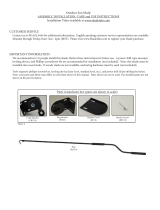
Bungee
(BUN18)
Bungee Bracket
(BUNB18)
Bungee Screw
(BUNSC18)

WALL MOUNT
Figure B
Figure C
Your shade can be installed against a wall (Fig B) or against a ceiling/overhang (Fig C).
Your shade is already prepared for a wall
mount, with the crank on the right side
of the shade. If you need to prepare your
shade for a ceiling mount, or if you need
to move your crank to the left side of the
shade, please refer to the last page of this
manual.
CEILING MOUNT
Step 1: Mark holes for installation
An installation template has been
provided to help position your pilot holes. Start by temporarily attaching
your template to your mounting surface (Fig. D). Then drill your pilot
holes in the four marked dark zones (ideally in the center of each dark zone)
(Fig E).
Figure EFigure D
Be sure to mount the brackets to a wood stud. If a wood stud cannot be
located, an anchor must be used (not included). Visit your local hardware
store for more information.
Step 2: Install brackets
Install the Crank Bracket and Plug Bracket with the provided wood screws
(see Fig. F). Note: the Crank Bracket should be installed on the right side
of the shade. The Plug Bracket is designed to be placed on the left side of
the shade. See the last page if you need to change your crank location.
Figure F
Step 3: Install shade
To install your shade, start by attaching the Crank Plug into the Crank Bracket (Fig G).
Next, slide the Plug with pin into the Plug Bracket. Note: the Plug (with pin) should slide and click into the Plug Bracket (Fig
H).
Figure G Figure H
Figure I
Push brackets in, towards shade
to reduce slack
If your shade moves side-to-side, you may want
to adjust the brackets to reduce any movement
between the shade and the brackets.
To prevent your shade from moving from side-to-side, roll
your shade down and loosen the screws slightly. Push the
brackets in, towards the shade and retighten screws. (Fig I)

Ceiling Mount or Left Crank Operation (or both)
Figure J
Figure K
Figure N
Figure O
Figure P
Figure L
Figure M
WALL INSTALL, CRANK RIGHT
WALL INSTALL, CRANK LEFT
CEILING INSTALL, CRANK LEFT CEILING INSTALL, CRANK RIGHT
Your shade is prepared for a wall installation, with the Crank Bracket on the right side of the
shade. See Figure J for the default bracket conguration.
If you require the Crank Bracket on the left of the shade, or if you require a ceiling installa-
tion (or both), you will need to make a small change to your brackets.
To change your brackets, remove both Bracket Covers (Fig K). Remove the 2 screws from the Crank Bracket (Fig L) and the 3
screws from the Plug Bracket (Fig M).
After removing the screws from both brackets, rotate the hardware to match your install type (Figures N, O and P below).
(DEFAULT SETUP)
Important: if you move your Crank Bracket to the left side of your shade, you will need to remove and reverse the locations of your
Crank Plug and Plug with Pin to match the corresponding bracket. These plugs are pre-installed inside of your top tube
(not illustrated).
If you move your crank to the left of the shade, you will need to change the roll direction of your fabric to prevent the fabric from
interfering with the crank ring. To reverse the roll direction of your fabric, simply roll the shade down completely. After the fabric
is completely lowered, continue rolling the shade...it will roll itself up in the opposite direction.
Maintenance
To clean your shade, rinse with water and scrub with any non-abrasive cleaner (using bleach or other abrasive cleaners will void
your warranty). Roll shade down to air dry.
303.652.6164 (p) M1043
www.shadeinfo.com
Figure Q
Figure R
Figure S
Figure T
Securing your Fabric
Your shade includes a Bungee System to secure your fabric . To install the Bungee System, screw your Bungee Bracket into a
wood stud (Fig Q) with the two (2) provided Bungee Screws. Insert your Bungee through the Bottom Rail Ring (Fig. R) and back
through itself (Lark’s Head Knot) (Fig. S). Finally, latch the Bungee into the Bungee Bracket (Fig. T). Always roll your shade
up during windy conditions.
/


