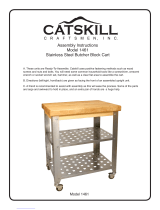
Catskill Craftsmen 1426 Operating instructions
- Category
- Multimedia carts & stands
- Type
- Operating instructions
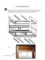
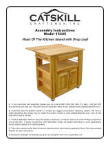
Catskill Craftsmen 1426 is a versatile storage solution that combines style and functionality. With its Ready-To-Assemble design and positive fastening methods, it's easy to build and customize. The unit features adjustable shelves, allowing you to tailor the storage space to your specific needs. The included drawer glides ensure smooth operation of the drawers, providing easy access to your belongings.
Catskill Craftsmen 1426 is a versatile storage solution that combines style and functionality. With its Ready-To-Assemble design and positive fastening methods, it's easy to build and customize. The unit features adjustable shelves, allowing you to tailor the storage space to your specific needs. The included drawer glides ensure smooth operation of the drawers, providing easy access to your belongings.


-
 1
1
-
 2
2
-
 3
3
-
 4
4
-
 5
5
-
 6
6
-
 7
7
-
 8
8
-
 9
9
-
 10
10
-
 11
11
-
 12
12
-
 13
13


Catskill Craftsmen 1426 Operating instructions
- Category
- Multimedia carts & stands
- Type
- Operating instructions
Catskill Craftsmen 1426 is a versatile storage solution that combines style and functionality. With its Ready-To-Assemble design and positive fastening methods, it's easy to build and customize. The unit features adjustable shelves, allowing you to tailor the storage space to your specific needs. The included drawer glides ensure smooth operation of the drawers, providing easy access to your belongings.
Ask a question and I''ll find the answer in the document
Finding information in a document is now easier with AI
Related papers
-
Catskill Craftsmen 1476 Installation guide
-
-
-
 CATSKILL 1461 Operating instructions
-
-
 CATSKILL 2005 Operating instructions
-
Catskill Craftsmen 91848 Installation guide
-
-
-


Other documents
-
Luxor WT1642 Operating instructions
-
-
-
POLYWOOD TD102GY Operating instructions
-
POLYWOOD TD101WH Operating instructions
-
 CATSKILL 15445 Assembly Instructions Manual
-
DUROGREEN AAC3529SETCH Operating instructions
-
Reznor JT4BE Installation guide
-
Broan Snow Stand Kit Installation guide
-
Honey-Can-Do CRT-01512 Operating instructions
