Page is loading ...

21
Content
1
Please observe the following ......................................................... 22
1.1
Emphasized sections ................................................................................................. 22
1.2
Items supplied............................................................................................................ 22
1.3
For your safety ........................................................................................................... 23
1.4
Field of application (Intended use) ............................................................................. 23
2
Description..................................................................................... 24
2.1
Operating elements and connections ......................................................................... 24
2.2
Theory of operation .................................................................................................... 25
3
Technical Data ............................................................................... 26
4
Installation ..................................................................................... 27
4.1
Environmental and operating conditions .................................................................... 27
4.2
Dimensions ................................................................................................................ 27
4.3
Initial start-up ............................................................................................................. 27
4.4
Mounting of the Stators .............................................................................................. 30
4.5
Mounting .................................................................................................................... 30
4.6
Mounting of the Pressure Sensors ............................................................................. 31
4.7
Connect the Dispenser .............................................................................................. 32
4.8
Priming of the Dispensers .......................................................................................... 32
4.9
Recommendations for problem-free operation ........................................................... 33
4.9.1
Mixing ratio with very short dispensing times ............................................................. 33
4.9.2
Retraction with dual-component media ...................................................................... 33
4.9.3
Note the pot life .......................................................................................................... 33
5
Maintenance and Cleaning ............................................................ 34
5.1
Disassemble .............................................................................................................. 34
5.2
Cleaning .................................................................................................................... 36
5.3
Assembling ................................................................................................................ 37
5.4
Maintenance .............................................................................................................. 37
6
Troubleshooting ............................................................................. 37
7
Annex ............................................................................................ 38
7.1
Spare Parts ................................................................................................................ 38
7.2
EC Declaration........................................................................................................... 38

22
1
Please observe the following
Before installing the system: For safe and successful operation of the unit, read these
instructions completely. If instructions are not observed, the manufacturer will not accept
any liability.
Be sure to keep the manual close at hand for further reference.
The WEEE symbol on this equipment indicates that this product may not be treated as
household waste. By ensuring this product is disposed of correctly you will help prevent
potential negative consequences for the environment. For more information about where
you can drop off your waste equipment for recycling, please contact your local city office
or your household waste disposal service.
1.1
Emphasized sections
Warning!
Refers to safety regulations and requires safety measures that protect the equipment
operator or other persons from injury or danger to life.
Caution!
Emphasizes what must be done or avoided so that the unit or other property shall not be
damaged.
☞
Note!
Gives recommendations for better handling of the unit during operation or adjustment as
well as for service activities.
The numbers printed in bold in the text refer to the corresponding item numbers in the
illustration on page 24-25.
The point emphasizes an instruction step.
Instruction steps in the illustrations are
indicated with arrows.
Where several instruction steps are
indicated in an illustration, the color
coding of the arrow has the following
meaning:
Black arrow = 1
st
step
Grey arrow = 2
nd
step
White arrow = 3
rd
step
1.2
Items supplied
– Volumetric Dual-Rotor Dispenser with Stators and Drive Units, Type MM25
Order No. 1774437
– Mounting tool, 2 screw drivers
– Operating manual
☞
Note!
As a result of technical development, the illustrations and descriptions in this operating
manual may deviate in detail from the actual unit delivered.

23
1
Please observe the following
1.3
For your safety
Please refer also to the relevant Technical Data Sheet for the adhesive to be processed.
Download from www.loctite.com or request the Technical Data Sheet and the Safety
Data Sheet (acc. to EC Directive 91/155/EC): Contact
Henkel AG & Co. KGaA
+49 89 92 68 11 67 for the English language version of the data sheet;
089-92 68 11 22 for the German language version of the data sheet.
INSTRUCTIONS given in these data sheets must be followed scrupulously at all
times!
While under warranty, the unit may be repaired by an authorized Henkel service
representative only.
Warning!
Improper handling of chemicals may result in potential health hazards!
Observe general safety regulations for the handling of chemicals!
Follow the manufacturer's instructions! Request a safety data sheet for the Loctite
®
product to be processed!
Very high dosing pressures can be produced, depending on the viscosity and the speed
of rotation, and this could result in unintended spurting out of the medium. The operating
pressure of the 2 component dispenser can be higher than the permissible pressure
value of the static mixer. Check the flow quantity in relation to the static mixer used.
When it is started up for the first time and after being refilled, air bubbles that are
included in the medium could cause an uncontrollable spurting out of the outlet nozzle.
Only start production operation once the 2 component dispenser has been completely
bled.
Only non-flammable cleaning agents are allowed!
Always wear goggles!
Ensure power supply is off whenever you connect or disconnect the connection cord of a
Dispenser. Otherwise the drive motor electronics might get damaged.
We cannot be held responsible for damage or injury of any kind because of failure to
observe the instructions in this Operating Manual.
1.4
Field of Application (Intended Use)
The volumetric Dual-Rotor-Dispenser dispenses 2 component Loctite
®
adhesives such
as anaerobic adhesives, acrylates and methyl amethacrylates (MMA) from 2component
product containers with high reproducibility. The upper limit of viscosity is 100,000 mPas.
Applications, for example, are the dispensing of drops, beads or potting.
Do not operate the controller in an explosive atmosphere.

24
2
Description
2.1
Operating elements and connections

25
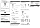
2
Description
1
Mixer Connection type B
2
Screws M3x10 for end piece
3
End piece
4
Screws M3x6 for mixer connection and pressure sensor part
5
Mixer Connection and Pressure Sensor Part
6
Screws M3x6 for pump housing end part
7
Pump Housing End Part
8
Stator with anti-twist
9
Pump Housing
10
Blind PlugG1/8 with sealing
11
Vent screw M4x8
12
Sealing Ring A 4.3
13
O Ring Ø 13 x 1.25
14
Threaded Pin (2 / Pump) to fix the drive
15
Star-shaped coupling DC drive
16
Connection Cord pump - controller
17
Drive
18
Screws M3x40 sealing housing
19
Rotor Sealing Housing
20
Feedling Fitting G1/8
21
Mounting bracket
22
Pressure Sensor M4
If pressure sensors are not used, these holes are closed with screw plugs
(standard delivery).
23
Sealing Ring pressure sensor
2.2
Theory of operation
The 2K dispenser uses a rotating displacement consisting of a rotor and a stator.
A number of voids are produced as a result of the various geometries of the conveying
elements. Conveying that is either proportional to the angle of rotation or else is rpm-
dependent is produced by the rotation of the rotor in the stator.
Since the direction of flow is reversible, the medium can be sucked back to allow a clean
break of the product. Self-sealing depends on the viscosity.

26
3
Technical Data
As a Single Rotor Pump
Volume per revolution
0,05 ml/U
Minimum Dispensing Quantity
0,01 ml
Accuracy
±1%
Volume Flow
0,01 bis 12 ml/m
Input Pressure, non-self-levelling liquid
0 - 20 bar
Max. Dispensing Pressure
0 to 40 bar*
Intrinsic tightness
ca. 2 bar
Speed rpm
0-120
Storage temperature
-10°C to +60°C (+14°F to +140°F), dry/dust
free
Operating temperature
+10°C to +40°C (+50°F to +104°F)
Dimensions (LxØ)
220 mm x Ø 35 mm
As a Dual Rotor Pump
Mixing Ratio
1:1 bis 10:1
Minimum Dispensing Quantity
0,01 ml
Volume flow
3
0,2 bis 12 ml/min
Weight
~ 1.100 kg
Reference medium, about 1,000 mPas at 20 ° Celsius
Maximum dispensing and self-sealing decrease with decreasing viscosity, depending on viscosity
and pressure of the medium.
All pressure data are maximum values for low to medium viscosity media.
Caution!
* Pay attention to the usable max. pressure of the mixer!

27
4
Installation
4.1
Environmental and operating conditions
– Keep product feedlines as short as possible. The shorter the feedline, the lower the
loss of pressure – and the shorter the required filling time.
– Avoid kinking of feedlines and pressure hoses.
– Typically, the pressure hose and product feedline should be no longer than 2 m.
– Do not use inflexible hoses and feedlines, so that unnecessary loads on the fittings will
be avoided.
– Carefully tighten all fittings.
– Avoid exposure to direct sunlight and UV radiation!
– The equipment should be installed in a dry, dust-free place.
4.2
Dimensions
4.3
Initial start-up
Caution!
Do not switch on the dispenser until product has been delivered to it. Otherwise there is
a risk of damage to the equipment. Even a brief period of dry running can lead to the
stator being destroyed.

28
4
Installation
4.4
Mounting of the Stators
● Remove end piece 3.
● Remove mixer connection and pressure
sensor part 5.
● Remove pump housing end part 7.

29
4
Installation
● Lube rotor with used product.
● Turn the stator 8 into the correct position on the rotor to ensure that the dowel pin can
be immersed in the relevant groove in the pump housing 9. Use assembly tool.
● Remove mounting tool.
● Mount the pump housing end part 7, mixer connection and pressure sensor part 5 and
end piece 3.
Perform the same installation steps for component B in the same order. Only then the
installation of the motors and the pressure sensors should be made!

30
4
Installation
4.5
Mounting
● Turn the set screws 14 in the thread such that they do not protrude into the coupling
area. Risk of damage to the fit.
● Check, if the star-shaped couplings 15 are attached onto the coupling of the drive units
A and B. If not, attach it.
● Couple the drive units A and B to the dispensing units until a gap of <1mm is achieved
between the antirotation lock and the dosing units.
● Position the anti-rotation lock correctly by turning the dosing units.
● Easily screw in the set screws 14 with ~ 0.1 Nm of torque. Drive units A respectively B
centered in the correct position.
● First, mount the mounting bracket 21 in
the correct position at the mounting
location. Then attach the pump to the
bracket plate.
Dimensions of the mounting bracket see
section 4.2.

31
4
Installation
4.6
Mounting of the Pressure Sensors
● Remove plug screw (Not shown) with sealing ring 23.
● Mount the pressure sensors 22 with the sealing rings 23 hand tight by using the
installation wrench supplied.
● Connect sensor cord.
Caution!
Handle sensor with absolute care!
No scratching or touching of the membrane (Face of sensor)!
Never exceed a pointed pressure load in the extremely thin and sensitive sensor
diaphragm.
Otherwise the sensor will be destroyed!

32
4
Installation
4.7
Connecting
Caution!
The connecting and disconnecting of the connection cable to the dispenser may be
made only when the controller is switched off. The electronics in the drive motor could
be damaged.
● Connect Dual Rotor Dispenser MM25 to the interfaces Pump 1 (Channel A) and
Pump 2 (Channel B).
4.8
Priming of the Dispensers
☞
Note!
The following steps must be performed in order.
● Mount feedline fittings and tubes of
components A and B to the
corresponding 1/8" terminals 20 of the
dispenser.
● Mount product fittings 20 (G1/8”) and
feedline of the components A and B to
the respective G1/8”threads 20 of the
dispenser.
● Mount mixer 1.

33
4
Installation
● If not done, put dispenser in a vertical
position. Mixer tip points downward.
● Open vent screw with sealing ring 11/12
on the pump.
Start with channel A and then with
channel B.
☞
Note!
Don´t loose the sealing ring 12.
Caution!
At first the initial filling of a sealing product from the interior of the dispenser is purged.
● Activate the controller dispensing program by pressing Start/Stop and start a
dispensing cycle.
● Stop dispensing.
Wipe off leaking product with a cloth and screw in the vent screw with sealing
ring 11/12 with a torque of ~0.35 Nm.
● Activate the controller dispensing program Start/Stop and start a dispensing cycle
again till the product is dispensed bubble free out of the mixer 1.
4.9
Recommendations for problem-free operation
☞
Note!
These experiences apply for a wide variety of dual-component adhesives. Always follow
the manufacturer recommendations for the used product in addition to these.
4.9.1
Mixing ratio with very short dispensing times
Dual component products usually have different properties (viscosity). They therefore
emerge from the outlets with different pressures. This means that deviations in the
mixing ratio can usually be noted at the start of dosing. Selecting a suitable mixing
nozzle is essential to the result.
4.9.2
Retraction with dual-component media
Retraction ensures a clean break of the dispensed product. If it is set too large, the
already mixed product enters the dispenser and as the product reacts will plug the
dispenser.
4.9.3
Note the pot life
Before breaks in work, rinsing (filling completely) the mixing nozzle with one of the two
components prevents the two components from reacting inside the mixing nozzle. As it is
not possible to prevent the two components from coming into contact on the outlets, this
measure is not suitable for every break in production.

34
5
Maintenance and Cleaning
5.1
Disassemble
● Disconnect the dispenser from the power supply at the controller.
● Remove feedlines.
● Remove mixer 1.
● Dismount end piece 3.
☞
Note!
If the end piece 3 should not be able to be
removed simply (stuck together with
product), then proceed as follows:
● Screw in screws 2 evenly in the
threaded holes to push it off.
● Remove mixer connection and pressure
sensor part 5.
● Remove carefulle both pressure
sensors.
● Remove pump housing end part 7.

35
5
Maintenance and Cleaning
● Attach mounting tool to the coupling at the rotor sealing housing 19. The coupling
star 15 has to be mounted to the coupling at the rotor sealing housing.
● Turn mounting tool in direction of arrow till the stator 8 comes out of the housing.
● Remove stator 8.
● Remove screws 18 from sealing housing 19 and remove sealing housing carefully.
Don´t loose o ring 13.
Caution!
All parts are wetted with adhesive!
● Unscrew the vent screw 11 and the sealing ring 12.
● Clean all parts.
☞
Note!
Do not flush rotor seal housing 19, the bearing can be damaged! Cleaning with a cloth
and brush.

36
5
Maintenance and Cleaning
5.2
Cleaning
This type of dispensing device requires some dismantling when cleaning with high
viscose products. Disassemble only as far as it is necessary for cleaning. During this
activity attention must be paid to the chemical properties and chemical reactions of the
products. Please contact the manufacturer of the used 2K product.
☞
Note!
In certain cases, flushing of the dispensing device may be easier than dismantling and
cleaning the components.
● Set the dispensing device to manual mode and secure against unauthorized operation.
● Remove the static mixer from the mixing head and dispose of in accordance with the
manufacturer instructions.
● Clean the connection thread/bayonet catch and holes.
Pay attention that the two components are not mixed.
● Hold the mixing head with the outlet pointing downwards and clean the holes (outlets)
individually.
Cleaning of the Outlets
Caution!
Disassemble both pressure sensors as a precaution to prevent damage to the sensor
surface. If damaged they cannot be used.
They are accessible when the mixer 1 is
removed.
● Catch withdrawing product and clean
the mixing head again. Be sure that the
2 components are not mixed. Use
separate cloths.
● Thread and holes of the mixing head
may protect against dehydration and
pollution, e. g. by a cap at the
appropriate places.

37
5
Maintenance and Cleaning
5.3
Assembling
Reassembly must be made in reverse order of the steps that are described
in section 5.1.
The following points should be observed:
– All screws on the dispenser housing
may only be tightened with a maximum
tightening torque of 0.35 Nm.
If the supplied screwdriver is used, it
corresponds approximately to this value
– Lube rotor with product.
– Turn the stator 8 into the correct position
on the rotor to ensure that the dowel pin
is inserted in the relevant groove in the
dispenser housing 9.
– When combining the end piece 5, the pump housing end part 7 and pump housing 9
ensure that they are parallel so that the dispensers can be assembled suitably to each
other at a later stage.
5.4
Maintenance
To ensure a smooth operation, we recommend the following maintenance intervals to be
observed.
daily
– Visual inspection of the entire system for contamination and clean if
necessary.
– Check for visible damage.
6
Troubleshooting
Malfunction/Fault signal
Possible Cause
Corrective Action
No or too little product.
– Mixer clogged.
– Stator swollen / worn.
– Dispenser speed too low.
– Inadequate supply of product.
– Motor not connected.
– Power connection faulty
● Replace mixer.
● Replace stator.
● Increase speed.
● Supply the product, check the
feedline, check the primary
pressure and increase it if
necessary.
● Connect motor.
● Check / connect.
Pressure too high, pressure
switch triggers
– Dispenser speed too high.
Pump speed too high in relation to
the product viscosity and mix nozzle
size.
– Product hardens.
● Reduce speed.
● Clean dispenser.
Dripping / running of the
product
– Air bubbles in the product
– Product compressible
● Bleed product.
● Degas product.

38
7
Annex
7.1
Spare Parts
Item no..
Description
Type no..
Order no
–
Repair Kit, consists of:
2 O rings (Viton) each
– 2,95 x 0,79, 13 x 1,25 (Kalrez), 15 x 1,5,
16 x 1,25, 17 x 1,25............................................................................
8955308
1335043
11
Stator with anti-twist .................................................................................
8955306
1335041
5 - 14
Pump unit without motor ..........................................................................
–
Sealing set with housing ..........................................................................
8955305
1335000
Caution!
Never operate the motor without a pump! Risk of injury when you grab onto the rotating
clutch claw.
7.2
EC Declaration
EC Declaration for Incorporation
according to 2006/42/EC dated 09 June2006, appendix IIB for incorporation of partly completed machinery.
The Manufacturer
according to the EC regulations
Henkel AG & Co. KGaA
Standort München
Gutenbergstr. 3
D-85748 Garching bei München
declares
– that the specified machine corresponds to the listed essential requirements of the directive 2006/42/EG,
where applicable the other directives and standards listed below,
– the relevant technical documentation is compiled in accordance with part B of Annex VI,
– the relevant technical documentation in accordance with part B of Annex VI will be transmitted in response
to a reasonable request by the national authorities in printed form or in electronic form.
Designation of the unit
Volumetric Dual-Rotor Dispenser, Type MM25
Unit number
1774437
Applicable EC Regulations
EC Directive of Machinery 2006/42/EC
Applied and fulfilled essential requirements
of the EC Directive of Machinery
1.1.2; 1.1.3; 1.1.5; 1.3.4; 1.3.7; 1.3.9; 1.5.1; 1.5.8
Additional applicable EC Regulations
EC Directive for Electro-Magnetic Compatibility 2004/108/EG
EC Directive of RoHS 2002/95/EG
EC Directive of WEEE 2002/96/EG
Applicable harmonized standards
DIN EN ISO 12100-1
DIN EN ISO 12100-2
DIN EN 809, DIN EN 61000-6-3:2011-09
DIN EN 61000-6-2:2011-06
Authorized person for technical files
Henkel AG & Co. KGaA
Standort München
Gutenbergstr. 3
D-85748 Garching
This partly completed machinery must not be put into operation until the final machinery into which it is to be
incorporated has been declared in conformity with the provisions of this Directive 2006/42/EG, where
appropriate.
Garching, April 30
th
, 2012
(J. von Ameln)
Business Director Adhesive Technologies

39
7
Annex
Edition/Ausgabe 04/2013
/