Page is loading ...

EQUIPMENT
Operation Manual
Loctite
®
Diaphragm Valve
Part Numbers 97135/97136

Contents
Page No.
1 Please Observe the Following . . . . . . . . . . . . . . . . . . . . . . . . . . . . . . . . . . . . . . . . . 1-2
1.1 Emphasized Sections . . . . . . . . . . . . . . . . . . . . . . . . . . . . . . . . . . . . . . . . . . . . . . . . . . . 1
1.2 Items Supplied . . . . . . . . . . . . . . . . . . . . . . . . . . . . . . . . . . . . . . . . . . . . . . . . . . . . . . . . 1
1.3 For Your Safety. . . . . . . . . . . . . . . . . . . . . . . . . . . . . . . . . . . . . . . . . . . . . . . . . . . . . . . . 2
1.4 Field of Application (Intended Usage) . . . . . . . . . . . . . . . . . . . . . . . . . . . . . . . . . . . . . . 2
2 Description . . . . . . . . . . . . . . . . . . . . . . . . . . . . . . . . . . . . . . . . . . . . . . . . . . . . . . . . . . 3
2.1 Theory of Operation . . . . . . . . . . . . . . . . . . . . . . . . . . . . . . . . . . . . . . . . . . . . . . . . . . . . 3
2.2 Operating Elements and Connections . . . . . . . . . . . . . . . . . . . . . . . . . . . . . . . . . . . . . . 3
3 Technical Data. . . . . . . . . . . . . . . . . . . . . . . . . . . . . . . . . . . . . . . . . . . . . . . . . . . . . . . . 4
4 Installation . . . . . . . . . . . . . . . . . . . . . . . . . . . . . . . . . . . . . . . . . . . . . . . . . . . . . . . . . 5-6
4.1 Connecting to the Product Reservoir . . . . . . . . . . . . . . . . . . . . . . . . . . . . . . . . . . . . . . . 5
4.2 Connecting to the Controller. . . . . . . . . . . . . . . . . . . . . . . . . . . . . . . . . . . . . . . . . . . . . . 6
5 Dispensing . . . . . . . . . . . . . . . . . . . . . . . . . . . . . . . . . . . . . . . . . . . . . . . . . . . . . . . . . . 7
5.1 Priming the Diaphragm Valve. . . . . . . . . . . . . . . . . . . . . . . . . . . . . . . . . . . . . . . . . . . . . 7
5.2 Adjusting the Dispensed Quantity . . . . . . . . . . . . . . . . . . . . . . . . . . . . . . . . . . . . . . . . . 7
5.3 Shutdown . . . . . . . . . . . . . . . . . . . . . . . . . . . . . . . . . . . . . . . . . . . . . . . . . . . . . . . . . . . . 7
5.4 Returning to Operation . . . . . . . . . . . . . . . . . . . . . . . . . . . . . . . . . . . . . . . . . . . . . . . . . . 7
5.5 Upgrading the Feed Line/Fitting . . . . . . . . . . . . . . . . . . . . . . . . . . . . . . . . . . . . . . . . . . . 7
6 Care, Cleaning, and Maintenance . . . . . . . . . . . . . . . . . . . . . . . . . . . . . . . . . . . . . 8-10
6.1 Cleaning . . . . . . . . . . . . . . . . . . . . . . . . . . . . . . . . . . . . . . . . . . . . . . . . . . . . . . . . . . . . . 8
6.2 Maintenance . . . . . . . . . . . . . . . . . . . . . . . . . . . . . . . . . . . . . . . . . . . . . . . . . . . . . . . . . . 8
6.2.1 Disassembly . . . . . . . . . . . . . . . . . . . . . . . . . . . . . . . . . . . . . . . . . . . . . . . . . . . . . . . . . . 9
6.2.2 Assembly . . . . . . . . . . . . . . . . . . . . . . . . . . . . . . . . . . . . . . . . . . . . . . . . . . . . . . . . . . . 10
7 Troubleshooting . . . . . . . . . . . . . . . . . . . . . . . . . . . . . . . . . . . . . . . . . . . . . . . . . . . . . 11
8 Annex . . . . . . . . . . . . . . . . . . . . . . . . . . . . . . . . . . . . . . . . . . . . . . . . . . . . . . . . . . . 12-13
8.1 Accessories and Spare Parts . . . . . . . . . . . . . . . . . . . . . . . . . . . . . . . . . . . . . . . . . . . . 12
8.2 Manufacturer’s Declaration. . . . . . . . . . . . . . . . . . . . . . . . . . . . . . . . . . . . . . . . . . . . . . 13
9 Warranty (Excluding Germany) . . . . . . . . . . . . . . . . . . . . . . . . . . . . . . . . . Back Cover

1. Please Observe the Following
1
1.1 Emphasized Sections
Warning!
Refers to safety regulations and required safety measures that protect the operator or other
persons from injury or danger to life.
Caution!
Emphasizes what must be done or avoided so that the unit or other property is not damaged.
Notice:
Gives recommendations for better handling of the unit during operation or adjustment as well as
for service activities.
The numbers printed in bold in the text refer to the corresponding position numbers in the
illustration on page 3.
• The point emphasizes an instruction step.
Instruction steps in the illustrations are indicated
with arrows.
When several instruction steps are indicated in
an illustration, the shading of the arrow has the
following meaning:
Black arrow = 1st step
Grey arrow = 2nd step
White arrow = 3rd step
1.2 Items supplied
(1) Diaphragm Valve 97135 or (1) Diaphragm Valve 97136
(1) Product Feed Line 1/4 inch
(1) Needle Variety Kit 97262
(1) Operating Manual
As a result of technical development, the illustrations and descriptions in this instruction manual
can deviate in detail from the actual unit delivered.
☞
☞

1. Please Observe the Following (continued)
1.3 For Your Safety
For safe and successful operation of the unit, read these instructions completely. If the instructions
are not observed, the manufacturer can assume no responsibility.
If chemical products are not properly handled, damage to health can result!
• Observe general safety regulations for the handling of chemicals!
• Observe manufacturer’s instructions!
• Request a safety data sheet for the Loctite
®
product used!
• When working with pressurized air, wear protective glasses!
1.4 Field of Application (Intended Usage)
The Diaphragm Valves 97135/97136 are suitable for the exact application of Loctite
®
products.
They show no suckback.
The Diaphragm Valve 97135 is equipped with an internal product bore of ø 2 mm. It is used for
anaerobic products up to a viscosity of 2,500 mPas.
The Diaphragm Valve 97136 is equipped with a internal product bore of ø 3 mm. It is used for
anaerobic thixotropic products up to a viscosity of 5,000 mPas.
For each product and corresponding application of the dispense valves, various dispensing needle
types and sizes are available:
- Conical dispensing needles, made of polyethylene, for viscous products and large
dispensed quantities.
- Stainless steel needles for thin fluids and UV curing products.
- Flexible dispensing needles of polyethylene.
For high flow rates, the diaphragm valve can be upgraded from feed line 1/4" to 3/8" by the feed
line upgrade kit 97220.
The diaphragm valve is used as a stationary applicator unit. It is mounted directly at the
dispensing position. The free end of the product feed line is connected to the product reservoir.
As product reservoirs, 0.5 liter and 2 liter tanks are available.
The control of the diaphragm valve is provided by a Loctite
®
control unit.
2

2. Description
2.1 Theory of Operation
The Loctite
®
product is transported through a product feed line to the diaphragm valve by the
dispensing pressure in the product reservoir. At the shut off valve assembly, PTFE material is used
for the area in contact with the adhesive to prevent curing of adhesive in this part of the
diaphragm valve. The opening of the diaphragm valve takes place by pressurizing an internal
single acting cylinder. In the inactive position, the diaphragm valve is closed by spring force.
Sealing in idle position is achieved by a piston pushing against a diaphragm which seals off the
product bore in the valve.
The floating mounted diaphragm enables easy repair and service. As a result the diaphragm valve
is not suitable for moisture sensitive product like cyanoacrylates.
The amount of product dispensed is controlled by:
- The amount of pressure in the reservoir.
- The length of time the shut off valve remains open.
- The dispensing needle.
The more precise and constant the amount of Loctite
®
product, the longer the dispensing time and
the lower the dispensing pressure.
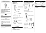
2.2 Operating Elements and Connections
1
2
3
4
5
6
7
1 Pressure hose connection
2 Actuator assembly
3 Diaphragm
4 Shut off valve assembly
5 Product feed line connection
6 Luer-Lok adapter
7 Luer-Lock
3

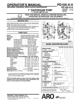
Clamping area
32
95
32
25.5
52
26.5
20
15
R1/8
R1/8
3. Technical Data
Pneumatic supply min. 5 bar (73 psi), max. 7 bar (100 psi)
Quality Filtered 10 µm, oil-free, non-condensing
If required quality is not achieved,
install a Loctite
®
filter regulator. Accessory Order No. 97120
Pneumatic hose size, control External dia. 4 mm; +0.05, -0.10
air connection Internal dia. 2.5 mm
Product Feed line Standard: 1/4 inch,
optional: Feed line Upgrade Kit 3/8 inch 97220
Dispensing pressure range of the valve: 0.5 bar (7 psi) - 4 bar (60 psi)
Weight 300 g
4
Dimensions (mm)

4. Installation
• Keep the pressure hose as short as possible. Short switch-on and switch-off times for the
diaphragm valve are within reach.
• Keep product feed lines as short as possible. The shorter the feed line the smaller the specific
resistance and the lower the dispensing pressure can be.
• Avoid kinking of feed lines and pressure hoses.
• Typically, the pressure hose and product feed line should not be longer than 2 m.
• Do not use inflexible hoses and feed lines, so that unnecessary loads on the fittings will
be avoided.
• Keep all fittings tight.
• No direct sunlight; no UV light!
4.1 Connecting to the Product Reservoir
R
0.5 ltr.: length 200 mm
2 ltr.: length 275 mm
5

4.2 Connecting to the Controller
When connecting to the coax-outlet (controller 97102 and 97204/97205) use Coax Adapter
8900102! When connecting to the single port, use port I and close port O.
97123
97007 – 97010 –
97017 - 97020
4. Installation (continued)
☞
M
a
d
e
i
n
G
e
r
m
a
n
y
A
B
R
6

5.1 Priming the Diaphragm Valve
To avoid air bubbles during dispensing, the product feed line and the diaphragm valve must
be filled.
Place a container under the diaphragm valve since the product will flow out.
• Perform the filling of the product feed line according to the operating manual of the
controller used.
5.2 Adjusting the Dispensed Quantity
Adjust the dispensing quantity according to the operating manual of the controller used.
5.3 Shutdown
To protect anaerobic products from curing, remove dispensing needle leaving Luer-Lok adapter 6
exposed to air.
Shutdown for longer periods.
• Remove product out of the reservoir.
• Purge the diaphragm valve with air until there is no product run out.
5.4 Returning to Operation
• Insert the product bottle into the reservoir.
• Purge the diaphragm valve with air until the product runs out.
Check the adjustment of the dispensing quantity according to Section 5 of the operating manual of
the controller used.
5.5 Upgrading the Feed Line/Fitting
For viscous products, a feed tube adapter with
a 9.5 mm product feed line is available by
ordering Part Number 97220.
• Disconnect the feed line and unscrew the fitting.
• Screw the new fitting into the shut off valve 4.
☞
5. Dispensing
☞
☞
7

6 Care, Cleaning, and Maintenance
6.1 Cleaning
The diaphragm valves need to be cleaned if:
- idle periods of the dispensing system exceed seven days, and/or
- a different type of product is to be dispensed and/or
- valves are disassembled for replacement of spare parts.
Liquid residues may be removed with several solvents. Chlorinated hydrocarbons will obtain
optimum results; acetone would be the best alternative among non-CHC solvents.
If chemical products are not properly handled, damage to health can result.
• Observe general safety regulations for the handling of chemicals!
If the diaphragm valve is cleaned after prolonged idle periods or for a switch to a different
product, be sure to place new Loctite
®
product bottle into the tank. See operating manual of the
reservoir used.
For priming of the feed line, see operating manual of the controller used.
For setting of dispensing parameters, see operating manual of the controller used.
6.2 Maintenance
To ensure trouble-free operation of the diaphragm valves 97135/97136, we recommend servicing
at regular intervals.
• Every 6 months
Replace diaphragm 3 (Repair Kit), Order code no. 97271.
The following is a description of diaphragm valve, disassembly and reassembly procedures:
8

6 Care, Cleaning, and Maintenance (continued)
6.2.1 Disassembly
• Disconnect the feed line and pneumatic tube
and remove dispensing nozzle.
• Disassemble Diaphragm valve
(2 open end wrenches size 17 mm).
• Carefully remove diaphragm 3 from shut
off valve 4.
Do not use metal tools! For example, use small
wooden spatulas or toothpicks. When the insert
is damaged, product can get in contact with the
housing and will cure.
• Clean the ring groove.
☞
9

6 Care, Cleaning, and Maintenance (continued)
6.2.2 Assembly
• Slightly grease threads and neck of actuator 2.
• Insert new diaphragm 3 in shut off valve 4.
• Screw actuator 2 onto shut off valve 4 and
tighten securely by hand, then by using
wrench size 17 mm, turn max 180° to fix them
correctly and get dispensing valve tight.
• Connect the feed line and pneumatic tube and slip on dispensing nozzle.
☞
10

Type of Malfunction Possible Cause Correction
No product or too little – Product feed line and/or pneumatic hose • Connect the product feed line correctly.
product. not connected correctly or kinked. If kinked, replace it.
– Control pressure not adequate. Control • Check and adjust the control pressure.
pressure must be between 5 and 7 bar.
– Curing in the product feed line or in the • Replace the product feed line and/or
dispensing needle. the dispensing needle.
– Curing in the diaphragm valve. • Replace the shutoff valve 4 and the
diaphragm 3.
– Controller incorrectly adjusted. • Check the controller setting (see
operating manual for the controller).
– Product reservoir not switched on, • Check the reservoir (see operating
depressurized or pressure is too low. manual for the product reservoir).
Diaphragm valve does – Actuator 2 of the valve is contaminated • Replace the actuator 2 and the
not open. with product. diaphragm 3.
Dispensing operation – Actuator 2 and shut off valve 4 are • Back off actuator from shut off valve,
is irregular. tightened too much. proceeding in small steps, 90° max
(1/4 turn).
Dispensing sequence – Disassemble valve and push button on • Replace the actuator 2 and the
too short despite long controller to actuate the actuator: diaphragm 3.
time setting. > air escapes at the plunger.
7. Troubleshooting
11

Pos. No. Description Loctite Order No.
2 Actuator 97254
3 Repair Kit Diaphragm 97271
(2) Sealing Adapter, 2.0 mm
(2) Sealing Adapter, 3.0 mm
(25) Diaphragm
4 Shut Off Valve Ø 2 mm 97268
4 Shut Off Valve Ø 3 mm 97269
– Dispense Needle, Polyethylene – Tapered,
especially for viscous products and large dispensing quantities:
Dispense Needle 16GA (50 pcs/box), grey 97221
Dispense Needle 18GA (50 pcs/box), green 97222
Dispense Needle 20GA (50 pcs/box), pink 97223
Dispense Needle 22GA (50 pcs/box), blue 97224
– Dispense Needle, Stainless Steel – Straight,
especially for low viscosity and UV curing products:
Dispense Needle 15GA (50 pcs/box), amber 97225
Dispense Needle 18GA (50 pcs/box), green 97226
Dispense Needle 20GA (50 pcs/box), pink 97227
Dispense Needle 25GA (50 pcs/box), red 97228
– Dispense Needle, Polypropylene – Flexible,
especially for fast curing products:
Dispense Needle 15GA (50 pcs/box), grey 97229
Dispense Needle 18GA (50 pcs/box), pink 97230
Dispense Needle 20GA (50 pcs/box), yellow 97231
Dispense Needle 25GA (50 pcs/box), red 97232
– Luer-Lok Tip Caps 97248
6 Luer-Lok-Adapter Kit 97233
– Feed Line, PTFE-lined, 1/4" 97972
– Feed Line Upgrade Kit 1/4" to 3/8" 97220
– Repair Kit Sealing Adapter 2.0 (for 97135) 8952235
– Repair Kit Sealing Adapter 3.0 (for 97136) 8952326
8 Annex
8.1 Accessories and Spare Parts
Also see the illustration on page 3.
☞
12

8 Annex (continued)
8.2 Manufacturer’s Declaration
The Manufacturer
declares that the machine contained in this delivery is the machine designated below, is
however incomplete and that its operation is prohibited until it can be determined that the
machine is in accordance with the provisions of EC machine.
Designation of the unit Diaphragm Valve
Unit number Product bore Ø 2 mm: 97135
Product bore Ø 3 mm: 97136
Applicable EC Regulations EG-Machine Regulations 98/37/EEC
Applicable harmonized standards DIN EN 292 Part 1; DIN EN 292 Part 2 11.1991
Date / Manufacturer’s signature 04/10/02
Information regarding the Signer General Manager (F. Löhr)
For changes to the unit that were not approved by Henkel Loctite,
this declaration loses its validity.
13

9. Warranty (Excluding Germany)
Henkel Loctite expressly warrants that all products referred to in this Instruction Manual for Diaphragm Valve 97135/97136
(hereafter called “Products”) shall be free from defects in materials and workmanship. Liability for Henkel Loctite shall be
limited, at its option, to replacing those Products which are shown to be defective either in materials or workmanship or to
credit to the purchaser the amount of the purchase price thereof (plus freight and insurance charges paid therefore by the
user). The purchaser’s sole and exclusive remedy for breach of warranty shall be such replacement or credit.
A claim of defect in materials or workmanship in any Products shall be allowed only when it is submitted to Henkel Loctite
in writing within one month after discovery of the defect or after the time the defect should reasonably have been
discovered and in any event, within twelve months after the delivery of the Products to the purchaser. No such claim shall
be allowed in respect of Products which have been neglected or improperly stored, transported, handled, installed,
connected, operated, used or maintained or in the event of unauthorized modification of the Products including, where
products, parts or attachments for use in connection with the Products are available from Henkel Loctite, the use of
products, parts or attachments which are not manufactured by Henkel Loctite.
No Products shall be returned to Henkel Loctite for any reason without prior written approval from Henkel Loctite. Products
shall be returned freight prepaid, in accordance with instructions from Henkel Loctite.
NO WARRANTY IS EXTENDED TO ANY EQUIPMENT WHICH HAS BEEN ALTERED, MISUSED, NEGLECTED, OR
DAMAGED BY ACCIDENT, OR IF THE SYSTEM USED TO DISPENSE ANY LIQUID MATERIAL OTHER THAN
LOCTITE PRODUCTS.
EXCEPT FOR THE EXPRESS WARRANTY CONTAINED IN THIS SECTION, HENKEL LOCTITE MAKES NO
WARRANTY OF ANY KIND WHATSOEVER, EXPRESS OR IMPLIED, WITH RESPECT TO THE PRODUCTS.
ALL WARRANTIES OF MERCHANTABILITY, FITNESS FOR A PARTICULAR PURPOSE, AND OTHER WARRANTIES OF
WHATEVER KIND (INCLUDING AGAINST PATENT OR TRADEMARK INFRINGEMENT) ARE HEREBY DISCLAIMED BY
HENKEL LOCTITE AND WAIVED BY THE PURCHASER.
THIS SECTION SETS FORTH EXCLUSIVELY ALL OF LIABILITY FOR HENKEL LOCTITE TO THE PURCHASER IN
CONTRACT, IN TORT OR OTHERWISE IN THE EVENT OF DEFECTIVE PRODUCTS.
WITHOUT LIMITATION OF THE FOREGOING, TO THE FULLEST EXTENT POSSIBLE UNDER APPLICABLE LAWS,
HENKEL LOCTITE EXPRESSLY DISCLAIMS ANY LIABILITY WHATSOEVER FOR ANY DAMAGES INCURRED
DIRECTLY OR INDIRECTLY IN CONNECTION WITH THE SALE OR USE OF, OR OTHERWISE IN CONNECTION WITH,
THE PRODUCTS, INCLUDING, WITHOUT LIMITATION, LOSS OF PROFITS AND SPECIAL, INDIRECT OR
CONSEQUENTIAL DAMAGES, WHETHER CAUSED BY NEGLIGENCE FROM HENKEL LOCTITE OR OTHERWISE.
Loctite is a registered trademark of Henkel Loctite Corporation, U.S.A.
© Copyright 2003. Henkel Loctite Corporation. All rights reserved. Data in this operation manual is subject to change without notice.
P/N8900423 Rev. A, 02/03
Loctite Industrial
Henkel Loctite Corporation
1001 Trout Brook Crossing
Rocky Hill, CT 06067-3910
Henkel Loctite Automotive
Technology Center
2455 Featherstone Road
Auburn Hills, Michigan 48326
Henkel Loctite Canada Inc.
2225 Meadowpine Boulevard
Mississauga, Ontario L5N 7P2
Henkel Ltda. Brazil
Av. Prof. Vernon Krieble, 91
06690-11-Itapevi
São Paulo-Brazil
Henkel Mexicana, S.A. de C.V.
Calzada de la Viga s/n, Fracc. Los Laureles
Loc. Tulpetlac, C.P. 55090
Ecatepac de Morelos, Edo. de México,
México
www.loctite.com
/