Page is loading ...

EPP-362
等离子电源
操作手册
Date: 01/2015
Part Number: 0558012280
Language: CN


EPP-362 Plasma Power Source
4

11
描述

15
安装

安装
16

安装
28

29
操作

操作
30

操作
35
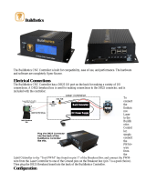
EPP-362J1(RAS)-接口示意图
CAN PS
CAN COMMUNICATION
ADAPTOR/JUNCTION BOX
CAN
ANALOG INTERFACE
CNC/程序控制器
PS启动连接
PS启动
PS启动
A
B
5导线电缆
14导线电缆
RAS盒
CAN PS
24伏交流
120伏交流
火线
PS24伏直流公共
24伏直流
PS24伏直流公共
120伏交流火线
划线模式开启
H.F.开启/换向阀
120伏交流零线
割炬类型选择
120伏交流零线
HF/V DR板
CAN通信
适配器/接线盒
CAN
模拟接口
120伏交流

操作
38

39
MAINTENANCE

Maintenan c e
40

Maintenan c e
41
General
ELECTRIC SHOCK CAN KILL!
SHUT OFF POWER AT THE LINE WALL DISCONNECT BEFORE AT
TEMPTING ANY MAINTENANCE.
WARNING
CAUTION
Maintenance On This Equipment Should Only Be Performed By
Trained Personnel.
Cleaning
Regularly scheduled cleaning of the power source is required to help keep the unit running trouble free.
The frequency of cleaning depends on environment and use.
1. Turn power o at wall disconnect.
2. Remove side panels.
3. Use low pressure compressed dry air, remove dust from all air passages and components. Pay particular
attention to heat sinks in the front of the unit. Dust insulates, reducing heat dissipation. Be sure to wear
eye protection.
Air restrictions may cause plasma unit to over heat.
Thermal Switches may be activated causing interruption of function.
Do not use air lters on this unit.
Keep air passages clear of dust and other obstructions.
WARNING
CAUTION
ELECTRIC SHOCK HAZARD!
BE SURE TO REPLACE ANY COVERS REMOVED DURING CLEANING
BEFORE TURNING POWER BACK ON.
Maintenance
WARNING
EYE HAZARD WHEN USING COMPRESSED AIR TO CLEAN.
• Wear approved eye protection with side shields when cleaning the power
source.
• Use only low pressure air.

Maintenan c e
42
Operation: The rotor reacts to turbulence, pulsation, entrained air, and other ow anomalies induced in the ow
stream by other process hardware. For optimum performance, install RotorFlow units where nominal ow condi-
tions exist, with ports located at the top. Incoming ow may be placed to either port. A minimum of 8° of straight
pipe on the inlet side is recommended. Frequency output (RFO) is determined by the velocity of the monitored
uid acting on the sensor rotor. Input piping with an orice smaller than that of the sensor input will eect the
sensor output.
Installation: RotorFlow sensors connect to piping via NPT mating thread forms. The following guidelines are
provided to assist with installation for a leak-free seal, without damage to the unit:
1. Apply pipe thread sealant to male pipe threads.
2. Thread RotorFlow unit onto male pipe thread until hand-tight.
3. Tighten pipe 1 to 1-1/2 additional turns.
4. If improper seal results, continue turning pipe into unit in ¼ turn increments.
Recommended Pipe Sealants: (a) Permatex “No More Leaks” (b) Teon Thread Tape.
Filteration and Cleaning: 150 micron lteration is recommended. However, should foreign particles enter the Ro-
torFlow sensor, accumulation is easily cleared by removing the lens from the body. The lens is removed by turn-
ing its center rib 45° counter-clockwise and then pulling it out. To reinstall the lens, simply reverse the process.
Pressure must be relieved from the system prior to sensor clean-out.
Flow sensor
RotorFlow Sensor is used to monitor the ow rate of the coolant.

Maintenan c e
44

46
TROUBLESHOOTING
46

47
TROUBLESHOOTING
47
Troubleshooting
ELECTRIC SHOCK CAN KILL!
DO NOT PERMIT UNTRAINED PERSONS TO INSPECT OR REPAIR
THIS EQUIPMENT. ELECTRICAL WORK MUST BE PERFORMED BY
AN EXPERIENCED ELECTRICIAN.
WARNING
Stop work immediately if power source does not work properly.
Have only trained personnel investigate the cause.
Use only recommended replacement parts.
CAUTION
Check the problem against the symptoms in the following troubleshooting guide. The remedy may be quite
simple. If the cause cannot be quickly located, shut o the input power, open up the unit, and perform simple
visual inspection of all the components and wiring. Check for secure terminal connections, loose or burned wir-
ing or components, bulged or leaking capacitors, or any other sign of damage or discoloration.
The cause of control malfunctions can be found by referring to the sequence of operations, electrical schematics
and checking the various components. A volt-ohmmeter will be necessary for some of these checks.
When the input power is applied to EPP-202 power source, pump motor should turn ON immediately, the power
light on the front panel will be ON and fault light will be OFF (if there are no errors/faults) indicating normal
operation.
Check the following:
1. If pump motor doesn’t turn ON, fuse(F3) might be bad or check for a bad connection to pump motor.
2. If POWER light doesn’t turn ON or main contactor and main fan doesn’t turn ON, then it could be
caused by blown fuses F1 or F2.
3. If the FAULT light is ON, then check the CNC/Process Controller display screen for the type of error
message from power source.
Fault Light, Main Contactor and Main Fan status for dierent errors/faults:
Troubleshooting Guide
Type of Fault Fault Light Status Fault Light Frequency K1 and Main Fan Status
Thermal or Ambient ON Continuous ON
Servo Fault TOGGLE 50% duty cycle with a
period of 1 second
OFF
All other Faults TOGGLE 50% duty cycle with a
period of 2 seconds
OFF

48
TROUBLESHOOTING
48
Help Codes
When fault light is in either one of the above-mentioned states, check the CNC/Process Controller screen
for the complete description of the error.
The list of errors with detail description for the power source are shown in the table below.
Error code Problem Solution
01 Supply Line Voltage exceeded or
dropped below + / - 15% of rated input
when machine is in Idle mode
1. Check the input voltage to the machine with a voltage meter.
2. Check the input power cable for correct size and resistance.
3. Check the Main Transformer (T1) voltage tapping connections.
4. Check the input fuses in the PS.
5. Check the input line fuses in the disconnect box.
6. Check the multi-color ribbon cable between J12 on PCB1 and J2 and PCB2.
02 Supply Line Voltage exceeded or
dropped below + or - 20% of rated
input while cutting
1. Check the input line voltages to the machine with a voltage meter.
2. Check the input power cable for correct size and resistance.
3. Check the Main Transformer (T1) voltage tapping connections.
4. Check the input fuses in the PS.
5. Check the input line fuses in the disconnect box.
6. Check the multi-color ribbon cable between J12 on PCB1 and J2 and PCB2.
7. Notify your power company of the line stiness issues.
03 Control Transformer not supplying
proper voltage to control board or the
+24 and +/-15 volt bias supplies are not
balanced
1. Check the input voltage taps on the control transformer.
2. Check the control transformer output voltages on TB3, if the voltages read within +/-15% of the specied value then
replace the control board else replace control transformer.
04 There is a thermal fault inside the
power supply. Fix any coolant ow er-
rors before investigating this error.
1. Wait 10 minutes for the unit to cool. If the thermal fault clears on its own then check for the ambient temperature
being above 40C or dirt in the radiators.
2. Check if main fan is functioning and it is pulling air through the power supply.
3. Shut o the power supply and allow the machine to cool.
4. Check the diode bridge for an open thermal switch. If the switch is still open after certain time then replace the switch.
5. Check the IGBT module for an open thermal switch. If the switch is still open after certain time then replace the switch.
05 CYCLE START signal is high while the
power source is booting up.
1. Check the start signal to the power supply while the power supply is OFF. If there is voltage on the input, nd and x
the wiring error.
2. Check the start signal to the power supply while the power supply is ON. If there is voltage on the input while CNC is
OFF, check the power supply control wiring for a short to the input.
06 Failed to re/ ignition did not take place
within 4 seconds after HF is turned ON.
1. Check the distance from the work piece matches the recommended ignition height.
2. Check the electrical connection from the work piece to the work connection on the power supply.
3. Check the HF relay inside the power supply.
4. Check the 115VAC voltage on the control transformer.
5. Check the consumables.
08 Torch error/Electrode current was pres-
ent before the PWM was enabled.
1. Check the jumper inside the RAS box between pins L and J on the 14-pin Amphenol connector.
2. Check for short between electrode and nozzle.
3. Check the IGBT gate pulse voltage connection on the driver board.
4. Check for shorted IGBT.
5. Check for shorted diode (D9).
09 Arc voltage is greater than 40V in Idle
mode.
1. Check for shorted IGBT.
2. Check for shorted diode (D9).
3. Check the arc voltage feedback connection on the driver board from the Electrode (-) terminal.
4. Check IGBT gate pulse voltage connection on the driver board.
11 Output current is greater than the
minimum idle current.
1. Check for shorted IGBT.
2. Check for shorted diode (D9).
3. Check the IGBT gate pulse voltage connection on the driver board. If there is positive voltage then replace the driver
board.
4. Check the hall sensors and their connections to the control board.
5. Replace the control board.
12 A phase of the input power is missing. 1. Check the fuses in the disconnect box for bad fuse.
2. Check the main contactor contacts for any damage.
3. Verify the input to the power supply is providing all 3 phases.
13 Open circuit voltage did not reach 280
volts within 200 msec.
1. Check for short between the electrode and nozzle.
2. Check for short between the electrode cable and a connection to the work output of the power supply.
3. Check for an open IGBT.
4. Check the IGBT gate pulse voltage connection on the driver board.
5. Check the multi-color ribbon connection from J12 on PCB1 to J2 on PCB2.
14 Ambient temperature exceeded 75° C
in control enclosure.
1. Check the temperature inside the control panel, if it reads below 55C and still the error is present then replace the
control board.
2. Cool the area around the power supply to below 40C. This is the upper limit of the rated operating range for the
power supply.
15 Bus voltage failed to reach 200 VDC
with in 500 ms.
1. Check for faulty input fuse.
2. Check for shorted bus lter capacitor.
3. Check the bus charger contactor (K2) contacts and coil for any damage.
4. Check the bus-charger contactor relay (RB1-1) for failure.
5. Check bus charger resistors connections.
6. Check the ribbon cable connection between J6 and Relay Module (RB1).
7. Check the multi-color ribbon cable connection between J12 on PCB1 to J2 on PCB2.
8. Check the 24VAC supply on the control transformer.

49
TROUBLESHOOTING
49
18 Output voltage fell below 70 volts
during cutting or below 40 volts during
marking.
1. Check for short in the torch cable.
2. Check cutting or marking height is too low.
3. Check for short between electrode and nozzle.
4. Check for short between Work (+) and Electrode (-) terminals on the power supply.
5. Check for coiled or looped up electrode or work cables.
20 Output or Arc voltage detected before
START signal issued
1. Check for a shorted IGBT.
2. Check the gate pulse voltage to IGBT from driver board. If there is a positive voltage during idle, replace the driver
board.
3. Check the IGBT gate pulse voltage connections and make sure they are as per schematics.
4. Check the arc voltage feedback connections on the driver board.
5. Check for shorted diode (D9).
6. Check the multi-color ribbon cable connection between J12 on PCB1 and J2 on PCB2.
21 Main contactor failed to engage or
disengage.
1. Check the input fuses inside the disconnect box.
2. Check the main contactor (K1) contacts.
3. Check the main transformer auxiliary windings connection on TB2 for 115VAC.
4. Check the relay RB1-2 on the relay module RB1.
5. Check the ribbon cable connection between J6 and relay module RB1.
22 Work current is greater than Electrode
current plus threshold limit during
cutting.
1. Check the feedback from the hall sensors.
2. Check the connection from hall sensors to the control board.
3. Replace the control board.
23 The power supply enable signal is
missing.
1. Check the power supply enable signal is present. This should be a dry contact output from the CNC.
2. Check for the power supply enable signal going to J1 connector on PCB1.
3. Check the enable signal contacts on K4 relay.
4. Check control transformer 24VAC voltage on TB3 powering K4 and K5.
5. Replace the control board.
24 There was an SPI communication error
between the main and servo micro on
control board.
1. Shut o the power supply for at least 5 minutes. If the error clears, check the grounding of the machine and the power
supply.
2. Replace the control board.
25 The EEPROM on the control has failed. 1. Shut o the power supply for at least 5 minutes. If the error clears, check the grounding of the machine and the power
supply.
2. Replace the control board.
27 The servo and supervisor on the control
board of the power supply has rmware
version mismatch.
Replace the control board.
28 Jumper in the RAS box is missing. 1. Check the jumper inside the RAS box between pins L and J on the 14-pin Amphenol connector.
2. Check for damaged control cable.
3. Replace the control board.
30 The servo on the control board has
fault.
1. Check for bad hall sensor.
2. Check for diode (D9) connection on the IGBT module bus bars.
3. Shut o the power supply for at least 5 minutes. If the error clears, check the grounding of the machine and the power
supply.
4. Replace the control board.
31 Coolant ow is below 0.45GPM. 1. Check the coolant level.
2. Check for a clogged lter.
3. Check for leaks in the coolant return line.
4. Check the bypass regulator for bypassing too much coolant.
5. Check input power to the pump.
6. Check for proper pump function by looking for ow into the tank. If there is no ow and the motor in running, replace
the pump head.
7. Check the connection of the ow sensor to the control board.
8. Check for the SW6 position set properly according the ow sensor either turbine ow or rotor ow sensor.
9. Replace the control board.
32 Coolant ow is above 2.4GPM. 1. Check the connection of the ow sensor to the control board.
2. Check for the SW6 position set properly according the ow sensor either turbine ow or rotor ow sensor.
3. Replace the control board.
33 There was a watchdog error on the
CAN bus.
1. Check the CAN connection between the interface control and the power supply’s control board.
2. Check the input power to the interface control.
3. Check for all the dip switches on the IC board are toward the display.
4. Check for SW5 on the control board in the power supply is set to “CLOSE”.
5. Check for coiling of the CAN cable near power leads.
34 Ignition/Arc lost in dwell state immedi-
ately after it attached to the plate.
1. Check that the piercing distance of the torch is at the recommended level.
2. Check that the ignition distance of the torch is at the recommended level.
3. Check the consumables.
35 The station constant’s CRC received
from the controller did not match the
calculated CRC.
This will normally correct itself, if not replace the control board.
39 Hall Sensor Connector is removed or
jumper is missing.
1. Check the hall sensor feedback connector for proper wiring.
/