Buildbotics CNC Controller Quick start guide
- Type
- Quick start guide

Buildbotics
The Buildbotics CNC Controller is built for compatibility, ease of use, and performance. The hardware
and software are completely Open-Source.
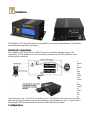
Electrical Connections
The Buildbotics CNC Controller has a DB25 I/O port on the back for making a variety of I/O
connections. A DB25 breakout box is used for making connections to the DB25 connector, and is
included with the controller.
To
connect
the
Endura
nce
Laser
to the
Buildb
otics
Control
ler,
simply
connect
the
PWM+
wire
from
the
Laser Controller to the “Tool PWM” line found on pin 17 of the Breakout Box and connect the PWM-
wire from the Laser Controller to one of the Ground pins on the Breakout box (pin 7 is a good choice).
Then plug the DB25 Breakout board into the back of the Buildbotics Controller.
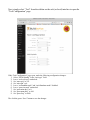
Configuration

Next, simply select “Tool” from the sidebar on the web (or local) interface to open the
“Tool Configuration” page.
With “Tool Configuration” page open, make the following configuration changes:
1. Select “PWM Spindle” in the “tool-type” field.
2. Leave “tool-reversed” unchecked.
3. Set “max-spin” to 255.
4. Set “min-spin” to 0.
5. Leave “tool-enable-mode” and “tool-direction-mode” disabled.
6. Leave “pwm-inverted” unchecked.
7. Set “pwm-min-duty” to 0.
8. Set “pwm-max-duty” to 100.
9. Set “pwm-freq” to 1000.
The click the green “Save” button to save the changes.
-
 1
1
-
 2
2


Buildbotics CNC Controller Quick start guide
- Type
- Quick start guide
Ask a question and I''ll find the answer in the document
Finding information in a document is now easier with AI
Other documents
-
MESA 7i92 User manual
-
ECG tb6560 User manual
-
Delta Tau PMAC2 PCI User manual
-
Delta Tau PMAC2 User manual
-
-
-
-
ESAB EPP-362 Plasma Power Source User manual
-
Eurotech Apollo Owner's manual
-