Chore-Time MF1255A MODEL C2® PLUS and MODEL G™ PLUS Feeding Systems Installation and Operators Instruction Manual
- Type
- Installation and Operators Instruction Manual

Model C2 Plus & G Plus
Feeding Systems
Installation & Operator’s Instruction Manual
MF1255-23 3/98
MF1255-29 6/98
MF1255AMay 1998

2
Model C2 Plus & G Plus Feeding Systems
Chore-Time Warranty
Chore-Time Equipment warrants each new product manufactured by it to be free from defects in material
or workmanship for one year from the date of initial installation by the original purchaser. If such a defect
is found by Chore-Time to exist within the one year period, Chore-Time will, at its option, (a) repair or
replace such product free of charge, F.O.B. the factory of manufacture, or (b) refund to the original
purchaser the original purchase price, in lieu of such repair or replacement.
Conditions and limitations:
1. The product must be installed and operated in accordance with instructions published by Chore-Time
or warranty will be void.
2. Warranty is void if all components of a system are not supplied by Chore-Time.
3. This product must be purchased from and installed by an authorized Chore-Time dealer or certified
representative thereof, or the warranty will be void.
4. Malfunctions or failure resulting from misuse, abuse, negligence, alteration, accident, or lack of
proper maintenance shall not be considered defects under this warranty.
5. This warranty applies only to systems for the care of poultry and livestock. Other applications in
industry or commerce are not covered by this warranty.
Chore-Time shall not be liable for any Consequential or Special Damage which any purchaser may suffer
or claim to have suffered as a result of any defect in the product. “Consequential” or “Special Damages”
as used herein include, but are not limited to, lost or damaged products or goods, costs of transportation,
lost sales, lost orders, lost income, increased overhead, labor and incidental costs and operational
inefficiencies.
THIS WARRANTY CONSTITUTES CHORE-TIME’S ENTIRE AND SOLE WARRANTY AND
CHORE-TIME EXPRESSLY DISCLAIMS ANY AND ALL OTHER WARRANTIES, INCLUDING,
BUT NOT LIMITED TO, EXPRESS AND IMPLIED WARRANTIES AS TO MERCHANTABILITY,
FITNESS FOR PARTICULAR PURPOSE SOLD AND DESCRIPTION OR QUALITY OF THE
PRODUCT FURNISHED HEREUNDER.
Any exceptions to this warranty must be authorized in writing by an officer of the company. Chore-Time
reserves the right to change models and specifications at any time without notice or obligation to improve
previous models.
CHORE-TIME EQUIPMENT, A Division of CTB, Inc.
P.O. Box 2000
Milford, Indiana 46542-2000 U.S.A.
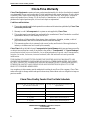
Chore-Time Poultry Feeder Pan Pro Rata Schedule
Year from date of installation during which
pan becomes unusable
Charge to be paid by the purchaser for
replacement.
0 - 1 years NO CHARGE
1 - 2 years NO CHARGE
2 - 3 years NO CHARGE
3 - 4 years 4/10 of then current list price
4 - 5 years 5/10 of then current list price

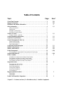
Table of Contents
Topic Page User*
*Legend: C = Customer (end user), D = Distributor (sales), I - Installer of equipment
Chore-Time Warranty . . . . . . . . . . . . . . . . . . . . . . . . . . . . . . . . . . . . . . . . . . . . . . . . 2 C,D
Support Information . . . . . . . . . . . . . . . . . . . . . . . . . . . . . . . . . . . . . . . . . . . . . . . . . 5 C,D
Distributor and Installer Information . . . . . . . . . . . . . . . . . . . . . . . . . . . . . . . . . . . 5 C
Safety Information . . . . . . . . . . . . . . . . . . . . . . . . . . . . . . . . . . . . . . . . . . . . . . . . . . . 6 C,I
Safety–Alert Symbol. . . . . . . . . . . . . . . . . . . . . . . . . . . . . . . . . . . . . . . . . . . . . . . . . . . . . . .6
Signal Words. . . . . . . . . . . . . . . . . . . . . . . . . . . . . . . . . . . . . . . . . . . . . . . . . . . . . . . . . . . . .6
DANGER: Moving Auger . . . . . . . . . . . . . . . . . . . . . . . . . . . . . . . . . . . . . . . . . . . . . . . . . .6
DANGER: Electrical Hazard. . . . . . . . . . . . . . . . . . . . . . . . . . . . . . . . . . . . . . . . . . . . . . . .6
Glossary of Terms. . . . . . . . . . . . . . . . . . . . . . . . . . . . . . . . . . . . . . . . . . . . . . . . . . . . 7 C,I
Glossary of Terms - continued . . . . . . . . . . . . . . . . . . . . . . . . . . . . . . . . . . . . . . . . . . . . . . .8
General Installation Information . . . . . . . . . . . . . . . . . . . . . . . . . . . . . . . . . . . . . . . 9 C,I
Capacities & Specifications . . . . . . . . . . . . . . . . . . . . . . . . . . . . . . . . . . . . . . . . . . . . 9 C,I
General Management & Start-Up. . . . . . . . . . . . . . . . . . . . . . . . . . . . . . . . . . . . . . . 10 C,I
Partial House Brooding. . . . . . . . . . . . . . . . . . . . . . . . . . . . . . . . . . . . . . . . . . . . . . . . . . . . 10
Electro-guard Operation . . . . . . . . . . . . . . . . . . . . . . . . . . . . . . . . . . . . . . . . . . . . . . . . . . . 10
Start-Up Information. . . . . . . . . . . . . . . . . . . . . . . . . . . . . . . . . . . . . . . . . . . . . . . . . . . . . . 11
Component Locations Diagram. . . . . . . . . . . . . . . . . . . . . . . . . . . . . . . . . . . . . . . . . 12 C,I
Model C2 Plus Features. . . . . . . . . . . . . . . . . . . . . . . . . . . . . . . . . . . . . . . . . . . . . . .13 C,D
Model G Plus Features. . . . . . . . . . . . . . . . . . . . . . . . . . . . . . . . . . . . . . . . . . . . . . . . 17 C,D
Feeder Management. . . . . . . . . . . . . . . . . . . . . . . . . . . . . . . . . . . . . . . . . . . . . . . . . . 19 C,D,I
General Operation of the Model C2 Plus and Model G Plus Feeders . . . . . . . . . . . . . . . . 19
Optional Slide Shut-Off . . . . . . . . . . . . . . . . . . . . . . . . . . . . . . . . . . . . . . . . . . . . . . . 19 C,D,I
Feeder Assembly. . . . . . . . . . . . . . . . . . . . . . . . . . . . . . . . . . . . . . . . . . . . . . . . . . . . . 20 I
Assembly Box Construction for Model C2 Plus Feeders. . . . . . . . . . . . . . . . . . . . . . . . . . 20
Pan Assembly Procedure for Model C2 Plus Feeders . . . . . . . . . . . . . . . . . . . . . . . . . . . . 22
Assembly Box Construction for Model G Plus Feeders. . . . . . . . . . . . . . . . . . . . . . . . . . . 24
Pan Assembly Procedure for Model G Plus Feeders . . . . . . . . . . . . . . . . . . . . . . . . . . . . . 26
Suspension System . . . . . . . . . . . . . . . . . . . . . . . . . . . . . . . . . . . . . . . . . . . . . . . . . . . 28 I
For systems up to 350’ (107 m).. . . . . . . . . . . . . . . . . . . . . . . . . . . . . . . . . . . . . . . . . . . . . 29
For systems over 350’ (107 m). . . . . . . . . . . . . . . . . . . . . . . . . . . . . . . . . . . . . . . . . . . . . . 30
Screw Hook Installation . . . . . . . . . . . . . . . . . . . . . . . . . . . . . . . . . . . . . . . . . . . . . . . . . . . 31
Ceiling Hook Installation . . . . . . . . . . . . . . . . . . . . . . . . . . . . . . . . . . . . . . . . . . . . . . . . . . 31
Power Winch Installation . . . . . . . . . . . . . . . . . . . . . . . . . . . . . . . . . . . . . . . . . . . . . . . . . . 33
Drop Installation . . . . . . . . . . . . . . . . . . . . . . . . . . . . . . . . . . . . . . . . . . . . . . . . . . . . . . . . . 34
Hopper Assembly Procedure. . . . . . . . . . . . . . . . . . . . . . . . . . . . . . . . . . . . . . . . . . . 36 I
200# Hopper . . . . . . . . . . . . . . . . . . . . . . . . . . . . . . . . . . . . . . . . . . . . . . . . . . . . . . . . . . . . 36
100# Hopper . . . . . . . . . . . . . . . . . . . . . . . . . . . . . . . . . . . . . . . . . . . . . . . . . . . . . . . . . . . . 38
Feeder Line Assembly & Suspension . . . . . . . . . . . . . . . . . . . . . . . . . . . . . . . . . . . . 40 I

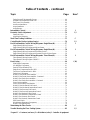
*Legend: C = Customer (end user), D = Distributor (sales), I - Installer of equipment
Table of Contents – continued
Topic Page User*
Feeder Pan and Tube Assembly Process . . . . . . . . . . . . . . . . . . . . . . . . . . . . . . . . . . . . . . 40
Assemble and Suspend the Feeder Line. . . . . . . . . . . . . . . . . . . . . . . . . . . . . . . . . . . . . . . 40
End Control Unit Assembly . . . . . . . . . . . . . . . . . . . . . . . . . . . . . . . . . . . . . . . . . . . . . . . . 44
Anti-Roost Installation . . . . . . . . . . . . . . . . . . . . . . . . . . . . . . . . . . . . . . . . . . . . . . . . . . . . 45
Auger Installation . . . . . . . . . . . . . . . . . . . . . . . . . . . . . . . . . . . . . . . . . . . . . . . . . . . . . . . . 48
Auger Brazing. . . . . . . . . . . . . . . . . . . . . . . . . . . . . . . . . . . . . . . . . . . . . . . . . . . . . . . . . . . 50
Intermediate Control . . . . . . . . . . . . . . . . . . . . . . . . . . . . . . . . . . . . . . . . . . . . . . . . . 51 I
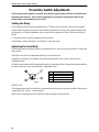
Proximity Switch Adjustment . . . . . . . . . . . . . . . . . . . . . . . . . . . . . . . . . . . . . . . . . .54 C,I
Setting the Delay. . . . . . . . . . . . . . . . . . . . . . . . . . . . . . . . . . . . . . . . . . . . . . . . . . . . . . . . . 54
Adjusting the Sensitivity. . . . . . . . . . . . . . . . . . . . . . . . . . . . . . . . . . . . . . . . . . . . . . . . . . . 54
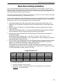
Meal-Time Feeding Guidelines . . . . . . . . . . . . . . . . . . . . . . . . . . . . . . . . . . . . . . . . . 55 C
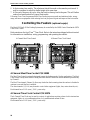
Controlling the Feeders (optional equip.). . . . . . . . . . . . . . . . . . . . . . . . . . . . . . . . . 56 C,I
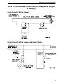
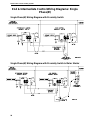
End & Intermediate Control Wiring Diagrams: Single Phase(Ø). . . . . . . . . . . . . 57 I
Single Phase(Ø) Wiring Diagram. . . . . . . . . . . . . . . . . . . . . . . . . . . . . . . . . . . . . . . . . . . . 57
Single Phase(Ø) Wiring Diagram with Motor Starter . . . . . . . . . . . . . . . . . . . . . . . . . . . . 57
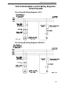
End & Intermediate Control Wiring Diagrams: Single Phase(Ø). . . . . . . . . . . . . 58 I
Single Phase(Ø) Wiring Diagram with Proximity Switch . . . . . . . . . . . . . . . . . . . . . . . . . 58
Single Phase(Ø) Wiring Diagram with Proximity Switch & Motor Starter. . . . . . . . . . . . 58
End & Intermediate Control Wiring Diagrams: Three Phase(Ø). . . . . . . . . . . . .59 I
Three Phase(Ø) Wiring Diagram: 220 V.. . . . . . . . . . . . . . . . . . . . . . . . . . . . . . . . . . . . . . 59
Three Phase(Ø) Wiring Diagram: 380/415 V. . . . . . . . . . . . . . . . . . . . . . . . . . . . . . . . . . . 59
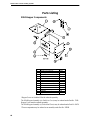
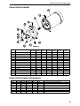
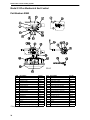
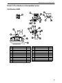
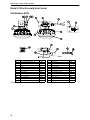
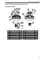
Parts Listing . . . . . . . . . . . . . . . . . . . . . . . . . . . . . . . . . . . . . . . . . . . . . . . . . . . . . . . . 60 C,D,I
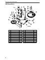
200# Hopper Components . . . . . . . . . . . . . . . . . . . . . . . . . . . . . . . . . . . . . . . . . . . . . . . . . 60
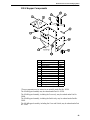
100 # Hopper Components . . . . . . . . . . . . . . . . . . . . . . . . . . . . . . . . . . . . . . . . . . . . . . . . . 61
Switch Kit (Part Number 8798) . . . . . . . . . . . . . . . . . . . . . . . . . . . . . . . . . . . . . . . . . . . . . 62
Single Boot Components Part No. 6822. . . . . . . . . . . . . . . . . . . . . . . . . . . . . . . . . . . . . . . 63
Twin Boot Components Part No. 6824. . . . . . . . . . . . . . . . . . . . . . . . . . . . . . . . . . . . . . . . 63
Feeder Line Components . . . . . . . . . . . . . . . . . . . . . . . . . . . . . . . . . . . . . . . . . . . . . . . . . . 64
Model C2 Plus Feeder Pan Assemblies . . . . . . . . . . . . . . . . . . . . . . . . . . . . . . . . . . . . . . . 65
Model C2 Plus Feeder Pan Assemblies - Continued . . . . . . . . . . . . . . . . . . . . . . . . . . . . . 66
Model G Plus Feeder Pan Assemblies . . . . . . . . . . . . . . . . . . . . . . . . . . . . . . . . . . . . . . . . 67
Model G Plus Feeder Pan Assemblies - Continued . . . . . . . . . . . . . . . . . . . . . . . . . . . . . . 68
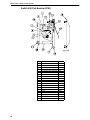
Power Unit Assemblies. . . . . . . . . . . . . . . . . . . . . . . . . . . . . . . . . . . . . . . . . . . . . . . . . . . . 69
Power Unit Assembly Part Numbers:. . . . . . . . . . . . . . . . . . . . . . . . . . . . . . . . . . . . . . . . . 69
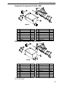
Model C2 Plus Mechanical End Control . . . . . . . . . . . . . . . . . . . . . . . . . . . . . . . . . . . . . . 70
Model C2 Plus Mechanical Intermediate Control . . . . . . . . . . . . . . . . . . . . . . . . . . . . . . . 71
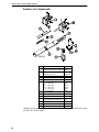
Model C2 Plus Proximity End Control. . . . . . . . . . . . . . . . . . . . . . . . . . . . . . . . . . . . . . . . 72
Model C2 Plus Proximity Intermediate Control. . . . . . . . . . . . . . . . . . . . . . . . . . . . . . . . . 73
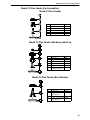
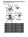
Model G Plus Mechanical End Control . . . . . . . . . . . . . . . . . . . . . . . . . . . . . . . . . . . . . . . 74
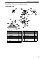
Model G Plus Mechanical Intermediate Control . . . . . . . . . . . . . . . . . . . . . . . . . . . . . . . . 75
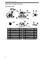
Model G Plus Proximity End Control. . . . . . . . . . . . . . . . . . . . . . . . . . . . . . . . . . . . . . . . . 76
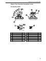
Model G Plus Proximity Intermediate Control. . . . . . . . . . . . . . . . . . . . . . . . . . . . . . . . . . 77
2883 Power Winch . . . . . . . . . . . . . . . . . . . . . . . . . . . . . . . . . . . . . . . . . . . . . . . . . . . . . . . 78
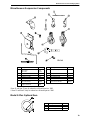
Miscellaneous Suspension Components. . . . . . . . . . . . . . . . . . . . . . . . . . . . . . . . . . . . . . . 79
Model G Plus Optional Item. . . . . . . . . . . . . . . . . . . . . . . . . . . . . . . . . . . . . . . . . . . . . . . . 79
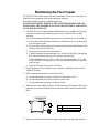
Maintaining the Floor Feeder . . . . . . . . . . . . . . . . . . . . . . . . . . . . . . . . . . . . . . . . . . 80 C
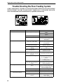
Trouble Shooting the Floor Feeding System . . . . . . . . . . . . . . . . . . . . . . . . . . . . . . 82 C,I

Model C2 Plus & G Plus Feeding Systems
5
Support Information
The Chore-Time Model C2 Plus & G Plus Feeding Systems are designed to feed poultry feed types. Using
this equipment for any other purpose or in a way not within the operating recommendations specified in this
manual will void the warranty and may cause personal injury.
This manual is designed to provide comprehensive planning, installation, operation, and parts listing
information. The Table of Contents provides a convenient overview of the information in this manual. The
Table of Contents also specifies which pages contain information for the sales personnel, installer, and
consumer (end user).
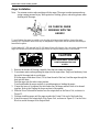
IMPORTANT: CE stands for certified Europe. It is a standard which
equipment must meet or exceed in order to be sold in Europe. CE
provides a benchmark for safety and manufacturing issues. CE is
required only on equipment sold in Europe.
Chore-Time Equipment recognizes CE Mark and pursues compliance
in all applicable products. Fill in the CE-Mark serial number in the
blank space provided for future reference.
(CE-mark serial number)
Distributor and Installer Information
Please fill in the following information about your Product.
Keep this manual in a clean, dry place for future reference.
Distributor’s Name___________________________________________________
Distributor’s Address ________________________________________________
Distributor’s Phone _______________________Date of Purchase ___________
Installer’s Name _____________________________________________________
Installer’s Address___________________________________________________
Installer’s Phone _______________________ Date of Installation ___________
System Specifications________________________________________________
___________________________________________________________________

6
Model C2 Plus & G Plus Feeding Systems
Safety Information
Caution, Warning and Danger Decals have been placed on the equipment to warn of potentially
dangerous situations. Care should be taken to keep this information intact and easy to read at all times.
Replace missing or damaged safety signs.
Using the equipment for purposes other than specified in this manual may cause personal injury and or
damage to the equipment.
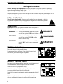
Safety–Alert Symbol
This is a safety–alert symbol. When you see this symbol on your equipment, be alert to
the potential for personal injury. This equipment is designed to be installed and operated
as safely as possible...however, hazards do exist.
Signal Words
Signal words are used in conjunction with the safety–alert symbol to
identify the severity of the warning.
DANGER
........... indicates an imminently hazardous situation
which, if not avoided, WILL result in death
or serious injury.
WARNING
........ indicates a potentially hazardous situation
which, if not avoided, COULD result in
death or serious injury.
CAUTION
.......... indicates a hazardous situation which, if not
avoided, MAY result in minor or moderate
injury.
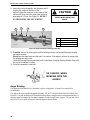
DANGER: Moving Auger
This decal is placed on the Panel Weldment.
Severe personal injury will result, if the electrical power is not
disconnected, prior to servicing the equipment.
DANGER: Electrical Hazard
Disconnect electrical power before inspecting or servicing equipment
unless maintenance instructions specifically state otherwise.
Ground all electrical equipment for safety.
All electrical wiring must be done by a qualified electrician in
accordance with local and national electric codes.
Ground all non-current carrying metal parts to guard against electrical
shock.
With the exception of motor overload protection, electrical disconnects
and over current protection are not supplied with the equipment.
DANGER
WARNING
CAUTION

Model C2 Plus & G Plus Feeding Systems
7
CAUTION:
Use caution when working with the Auger--
springing auger may cause personal injury.
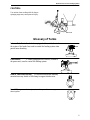
Glossary of Terms
Intermediate Control:. . A feeder, equipped with a switch, (located near
the center of the feeder line) used to control the feeding system when
partial house brooding.
End Control: . . . . . . A feeder, equipped with a switch, (located at
the power unit), used to control the feeding system.
Item #1 Anti-Roost Bracket: . . An insulator and bracket assembly
mounted on every fourth or fifth clamp to support shocker wire.
Item #2 Clamp: . . . . . .A two-piece, riveted strap used to secure auger
tubes together.
Manboot 3/98

Model C2 Plus & G Plus Feeding Systems
8
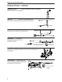
Glossary of Terms - continued
Adjustment Leveler:. . . . . . .A cable locking devise used to conveniently
adjust the feeder to a level position.
Drop Line: . . . . . . . . . .A section of cable fastened to the
main cable, routed through a pulley, down to the feeder line.
Throw-back: . . . A cable/pulley arrangement that
allows cable to be routed to a desired location.
Double-back:. . .A cable/pulley
arrangement that reduces the load
on the Power Winch.
Power Lift:. . . . .Red, cast iron winch used to raise and lower the
feeder line(s). Operated by a hand crank or electric drill. Referred to as
Power Winch.
Electro-Guard: . . A high voltage, low
current shocking device used to keep birds
from setting on the feeder line.

Model C2 Plus & G Plus Feeding Systems
9
General Installation Information
Please read the installation instructions in this manual prior to beginning the installation.
This manual provides the necessary information on the installation, operation, and
maintenance of the Chore-Time feeding equipment you have purchased.
The feeder pan assembly is different for each of the feeder systems. Refer to the applicable
feeder pan assembly section.
The suspension, hopper assembly, feeder line installation, and Anti-Roost installation is the
same for each system, except where noted otherwise. Please pay particularly close attention
to insure proper assembly and installation of the equipment.
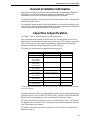
Capacities & Specifications
The Model C2 Plus, G Plus Feeders all use plastic feeder pans.
Each of the feeders may be used on broilers from 1 day old through the grow-out. The
feeders are also recommended for turkey poults from 1 day old to 5 weeks old, and turkey
hens 6 to 14 weeks old*. Each feeder has adjustability features built-in, allowing the
operator to manage the feeding system effectively and efficiently.
The chart below provides the recommended birds-per-pan ratio.
*The Model G Plus Feeder with Pan Lip Extension is the only feeder recommended for use with turkey hens
from 6 to 14 weeks old.
Suspension systems are based on ceiling heights of 14 feet (4.26 m) with suspension drop
points every 8 feet (2.4 m). DO NOT EXCEED 10 FEET (3 M) BETWEEN SUSPENSION
DROPS. Refer to the suspension section in this manual for installation details.
The Agri-Time Meal-Time Control is used to control the Model C2 Plus, G Plus Feeders.
The optional Agri-Time Time Clock Control may be used in certain installations where the
Meal-Time feature is not required.
The Feeder Control Units should be at least 10 feet (3 m) from the wall or partition. See
diagrams on page 11.
Type of Bird Recommended Feeder Birds Per Pan
Broiler Model C2 Plus, G Plus 60 to 75
Broiler Breeder Model C2 Plus, G Plus 14 to 15
Commercial Leghorn
Pullet or Hen
(0 to 18 weeks)
Model C2 Plus, G Plus 20 to 25
Commercial Leghorn
Pullet or Hen
(19 to 65 weeks)
Model C2 Plus, G Plus 45 to 50
Turkey Poults
(0 to 0 weeks)
Model C2 Plus, G Plus 60 to 65
Turkey Poults
(5 to 17 weeks)
Model G Plus
(with Pan Lip Extension*)
40 to 45
Ducks
(0 to 3 weeks)
Model G Plus 60 to 70
Ducks
(4 to 8 weeks)
Model G Plus 50 to 60
Ducks Layer Model G Plus 40 to 45
Guinea
(0 to 8 weeks)
Model G Plus 45 to 55

Model C2 Plus & G Plus Feeding Systems
10
The Model C2 Plus, G Plus Control Units use a 348 R.P.M. Gearhead, delivering
approximately 17 pounds per minute or 7.7 kg per minute. This rating is based on feed with
a density of 40 pounds per cubic foot or 640 kg per cubic meter.
Single phase 60 Hz and single and three phase 50 Hz Power Units are available for the
Model C2 Plus , G Plus Feeders.
Systems up to 300’ (91 m) require 1/3 H.P. Power Units. Systems over 300’ (91 m) require
1/2 H.P. Power Units.
General Management Recommendations that apply to Model C2 Plus, G Plus Feeder
systems are covered below. In addition, each style of feeder has a section, explaining some
of its individual features. Refer to the section that applies to the feeder you have purchased.
The Model C2 Plus Features are covered on pages 12 through 14.
The Model G Plus Features are covered on page 15.
These sections provide you with valuable information concerning feeder installation,
operation, etc. It is important that you read this information and understand how the feeder
was designed to operate. Then, you may custom operate the system to fit your individual
needs.
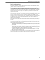
General Management & Start-Up
Partial House Brooding
It is recommended that the power unit end of the house be used for the brooding area. This
helps avoid any section of the system running dry. Also, Intermediate Controls are not
needed in this situation. Houses over 400’ (122 m) should be split in the center, allowing
either end to be used for partial house brooding.
If partial house brooding is required, the Intermediate Control is available.
With the recommended toggle switch wired into the system, the feeder line can be changed
from full house brooding to partial house brooding with the flip of a switch.
Maintain a lower feed level in the Intermediate Control than in the rest of the feeders. This
will cause the Intermediate Control Pan to empty more often, thereby starting the feeder
line before the other pans become empty.
Do not hinder the bird movement around the Intermediate Control pan. Locate the curtain
or partition several pans away from the Intermediate Control pan.
Provide adequate lighting so that the birds will not shy away from the Intermediate Control
area.
Electro-guard Operation
Electro-guard cables should be tight to prevent sagging onto the feeder and shorting out.
Tight cables also help keep pans in line on the tube.
The feeding equipment must be grounded through the power unit wiring or a separate
ground wire for the electro-guard to work properly.
Electro-guard chargers should be operated on a separate circuit so the anti-roost system can
be disconnected using a switch at the door when someone enters the pen. Birds are less
likely to become wild and flighty if the electro-guard can be disconnected when people are
in the house.

Model C2 Plus & G Plus Feeding Systems
11
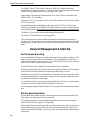
Start-Up Information
Operate the equipment, if possible, before birds are housed to check installation, switch
operation, and fill the feeder lines with feed.
The oil coating on new auger will cause the auger to deliver feed at a slower rate. To reduce
the load on the motor while the equipment is being broken in, auger 50 pound (20 kg)
increments of feed out to the pans. Allow the system to run for approximately 30 seconds,
then add another 50 pounds (20 kg) of feed. Repeat this procedure until feed has been
supplied to all the pans.
Birds avoid dark or cold areas. Do not locate a control unit or intermediate control in such
an area. Also, do not locate the Control Unit close to the end of the building. Allow a
minimum of 10 feet (3 m) between the Control Unit and the building wall. If these problems
are anticipated, they can be avoided during installation. Later, artificial lighting can
partially correct the problem.
During the first 5 days the system should be run manually with the feeder pans setting on
the floor.
If the system accidentally runs out of feed and birds are without feed for some time, care
must be taken when the pans are refilled.
Feed hoppers can be filled prior to starting the feeder lines to give the fill system
a head start.
When feeders are turned on, it may be necessary to walk up and down the lines
to scatter large groups of birds as they rush to the feeders.
It may be desirable to raise the feeder line so birds cannot reach it, fill all the
pans, then carefully lower the line.
When birds are removed, all the remaining feed in the hoppers and the feeder pans must be
removed. If possible, allow the birds to clean up feed prior to their removal.

12
Model C2 Plus & G Plus Feeding Systems
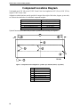
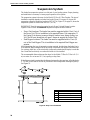
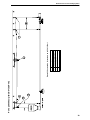
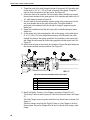
Component Locations Diagram
Line lengths up to 300’ (90 m) use 1/3 H.P. Power Units. Line lengths from 300’ (90 m) to 500’ (152 m)
require 1/2 H.P. Power Units.
Adequate overhead structure must be provided to support the weight of the feeder, hoppers, power units,
etc. Refer to the chart below for individual component weights.
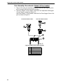
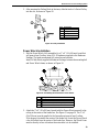
Optional Intermediate Controls may be used for partial house brooding. See Figure 1.
Figure 1. Component location diagram for systems up to 400 feet (122 m). (Top View).
Component Weight in pounds (kg)
Tube, Auger, Feeders, & Feed 5 lbs. (2.26 kg) per linear foot (.3 m)
Power Unit & Control Unit Assembly 50 lbs. (22.6 kg)
200 lbs. Feed Hopper & Feed 250 lbs. (113.4 kg)
100 lbs. Feed Hopper & Feed 150 lbs. (68 kg)
Power Winch 40 lbs. (18.1 kg)
Key Description
1Feed Bin
2Feed Hopper
3 Intermediate Control
4Brood Curtain
5 End Control/Power Unit
610’ (3 m) minimum
7 Up to 400’ (122 m)

Model C2 Plus & G Plus Feeding Systems
13
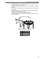
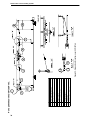
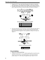
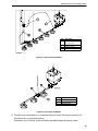
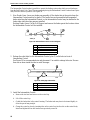
Systems with line lengths over 400’ (122 m) should be split in the center, as shown in
Figure 2. This will reduce auger running time and eliminate the need for Intermediate
Controls for partial house brooding.
Figure 2. Component location diagram for systems over 400 feet (122 m). (Top View).
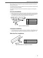
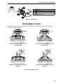
Model C2 Plus Features
The Model C2 Plus Feeder is designed to be used on broilers, cockerels, pullets and
hens from day old through grow out.
Figure 3. Model C2 Plus Feeder
Key Description
1Feed Bin
2Feed Hoppers
310’ (3 m) minimum
4Brood Curtain
5 End Controls/Power Unit
6 Over 400’ (122 m)
Standard Model C2 Plus Feeder
(With Feed Windows)
1-Piece Model C2 Plus Feeder
(Windowless)

Model C2 Plus & G Plus Feeding Systems
14
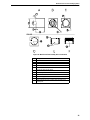
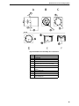
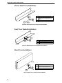
The Model C2 Plus Feeder has a variety of features as shown in Figures 4 through 10.
The Model C2 Plus Feeder components are all plastic to avoid rust and corrosion while
providing years of trouble free service. See Figure 4.
Figure 4. Model C2 Plus Plastic Parts
The C2 Plus Feeder is designed to operate with the Feed Windows OPEN or CLOSED with
the feeder on the floor or suspended.
The 1-Piece (windowless) version is available for applications where the windows feature
(flooding the pan w/ feed) is not required.
Figure 5. Model C2 Plus Feeder with window
Item Description
1 Two-Piece Cone Top
2 One-Piece Cone
3Feeder Pan
4 Feeder Grill
5 Two-Piece Cone Bottom
MF1255-22 3/98
1
2
3
4
5
MF1255-23 3/98

Model C2 Plus & G Plus Feeding Systems
15
Adjustment settings are easy to understand and change. Settings numbers are embossed on
both sides of the grill, so they may be easily seen from either side of the feeder line.
Figure 6. Adjustment Settings (Top View)
It is easy to determine the amount of feed opening in the bottom of the pan. It is equal to
the distance from the top of the grill to the top of the cone adjustment, when the feeder is
suspended.
Figure 7. Feed Opening Dimension
Item Description
13/4” (19.05 mm)
MF1255-24 3/98

Model C2 Plus & G Plus Feeding Systems
16
The pans are easily turned on the grill using the turn tabs formed on the side of the pan. See
Figure 8.
Figure 8. Formed Tabs on Pan
The standard feeder uses a one piece Support Cone as shown in Figure 9. The Removable
Top Support Cone, not shown, is also available.
Figure 9. One-Piece Swinging Support Cone
Item Description
1 Turn Tabs
2 Pan Hanger
3Feeder Pan
MF1255-25 3/98
2
1
3
MF1255-26 3/98

Model C2 Plus & G Plus Feeding Systems
17
The Feeder Pans may be removed from the grill, for easy cleaning, and remain attached for
convenience, as shown in Figure 10.
Figure 10. Disasembled Feeder Assembly for Cleaning
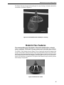
Model G Plus Features
The recommended usages of the Model G Plus Feeder include broilers, cockerels,
turkeys, and ducks. The Model G Plus may also be used to feed other types of birds.
The Model G Plus Feeders shown in Figure 11 has a 8 spoke grill which allows ample feed
access for large birds. Features include a high cone feed pan and a Feed Level Tube with
feed fins to provide minimal feed wastage. A valuable feature of the Model G Plus is feed
flood windows which allows the feeder pan, when lowered to the floor, to be filled with
feed for the brooding of young birds. The optional Pan Extension may be used to prevent
feed wastage on large birds.
Figure 11. Model G Plus Feeder
MF1255-27 3/98
MF1255-29 6/98

Model C2 Plus & G Plus Feeding Systems
18
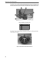
The Model G Plus is available with the standard adjustable windowed Grill Support or the
optional 1 piece (non-window) Grill Support. Both versions are shown in Figure 12. Both
the windowed and the non-windowed cones are available with a optional removable top
Figure 12. Model G Plus Plastic Parts
The Model G Plus with Pan Extension, shown below in Figure 13, will be used to finish
Turkey Hens to 14 weeks.
Figure 13. Model G Plus Feeder with Pan Extension
Item Description
1 Two-Piece Cone Bottom
2 Two-Piece Cone Top
3 One-Piece Cone
4 Feeder Pan
5 Feeder Grill
MF1255-28 3/98
4
3
2
1
5
MF1255-30 3/98

Model C2 Plus & G Plus Feeding Systems
19
Feeder Management
General Operation of the Model C2 Plus and Model G Plus Feeders
These recommendations are guidelines to aid producers in developing a feeding program. Many
factors such as feed content, type of bird, etc. may dictate change from these recommendations.
Start young birds with the feeder pans resting on the floor. The Model C2 Plus has the ability to fill the
feeders while setting on the floor or suspended. With the feed windows open, feed will spill out in the pan,
making it easier for the birds to find feed, adapt to the feeder, and begin to eat. Make sure all the feed
windows are in the same position, OPEN or CLOSED.
Raise the feeder as the birds grow. This will automatically close the feed windows. Chore-Time
recommends opening the feed windows in the pans for the first 5 to 10 days, for broilers. Open the feed
windows in the pans for the first 10 to 14 days, for turkeys. The feeders will need to be operated at least
twice a day for the first 5 days, thereafter pans may need to be resupplied 3 times a day or as birds eat feed
level down.
Keeping the pans at the proper height prevents birds from raking feed excessively. For additional
information on pan height adjustment refer to the diagram on page 20 in this manual.
DO NOT RUN THE SYSTEM ON AUTOMATIC (FULL FEED) WHEN FEED WINDOWS ARE OPEN.
In most cases, setting #4 is recommended. However, feed texture, fat content, type of bird, or some other
variables may make it necessary to change to another setting. The combination of proper pan height, feeder
setting, and time clock operation, will result in optimum feeder performance. The operator will learn what
works best for his/her situation by experience.
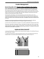
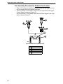
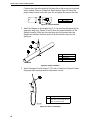
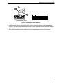
Optional Slide Shut-Off
An Optional Slide Shut-Off is available for Non-Windowed Feeder Assemblies. The Slide Shut-Off may be
used on either style of feeders.
To assemble the Slide Shut-Off to the Non-Window Feed Cone, remove the thinned area from the Non-
Windowed Feed Cone, then insert the Slide Shut-Off into the slots, as shown in Figure 14.
Figure 14. Optional Slide Shut-Off Assembly
Item Description
1Slide Shut-Off
2 Removed Portion of Non-Window Cone
3 Non-Window Cone
4 Thinned area on Non-Window Cone
MF1255-56 5/98
3
2
1
4
3

Model C2 Plus & G Plus Feeding Systems
20
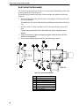
Feeder Assembly
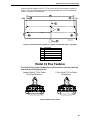
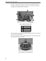
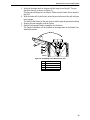
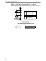
Assembly Box Construction for Model C2 Plus Feeders
This information and assembly only applies to Model C2 Plus installations.
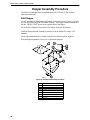
Chore-Time recommends building an assembly box to aid in assembling the Model C2 Plus
feeders.
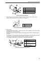
To build the assembly box for the C2 Plus Feeder, use a 16" (406 mm) square piece of
plywood and four 14-1/2" (368 mm) long pieces of 2 x 10 (20 x 250 mm), these can be cut
from a 5’ (1.5 m) section of 2 x 10 (50 x 250 mm).
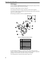
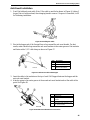
1. Cut a 3/4" (20 mm) piece of plywood 16" (400 mm) square. See Figure 15A.
Cut a 4" (100 mm) piece out of the middle of one side. See Figure 15A.
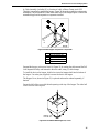
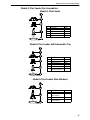
2. Center the grill on the 16" (400 mm) square piece of plywood. Use a pencil and
draw around the outside edge of the grill as shown in Figure 15B.
Mark a "V" at each strut location.Remove the grill.
Use a 7/8" (22 mm) spade bit to drill a hole at each strut location, as shown in
Figure 15C.
3. Use a sabre saw to cut along the inside circle, between the 7/8" holes. See
Figure 15D.
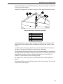
4. Use (4) 14-1/2" (370 mm) 2 x 10’s (50 x 250 mm) to construct the box sides.
Nail the 3/4" plywood fixture to the box. See Figure 15E.
It is important to use at least 10" (250 mm) sides for the box. Smaller lumber
will not allow sufficient depth for the grill to be placed in the box face down.
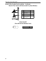
Figure 15F shows how the grill should fit down in assembly box. NOTE: Board
is cut away for clarity only.
Page is loading ...
Page is loading ...
Page is loading ...
Page is loading ...
Page is loading ...
Page is loading ...
Page is loading ...
Page is loading ...
Page is loading ...
Page is loading ...
Page is loading ...
Page is loading ...
Page is loading ...
Page is loading ...
Page is loading ...
Page is loading ...
Page is loading ...
Page is loading ...
Page is loading ...
Page is loading ...
Page is loading ...
Page is loading ...
Page is loading ...
Page is loading ...
Page is loading ...
Page is loading ...
Page is loading ...
Page is loading ...
Page is loading ...
Page is loading ...
Page is loading ...
Page is loading ...
Page is loading ...
Page is loading ...
Page is loading ...
Page is loading ...
Page is loading ...
Page is loading ...
Page is loading ...
Page is loading ...
Page is loading ...
Page is loading ...
Page is loading ...
Page is loading ...
Page is loading ...
Page is loading ...
Page is loading ...
Page is loading ...
Page is loading ...
Page is loading ...
Page is loading ...
Page is loading ...
Page is loading ...
Page is loading ...
Page is loading ...
Page is loading ...
Page is loading ...
Page is loading ...
Page is loading ...
Page is loading ...
Page is loading ...
Page is loading ...
Page is loading ...
Page is loading ...
-
 1
1
-
 2
2
-
 3
3
-
 4
4
-
 5
5
-
 6
6
-
 7
7
-
 8
8
-
 9
9
-
 10
10
-
 11
11
-
 12
12
-
 13
13
-
 14
14
-
 15
15
-
 16
16
-
 17
17
-
 18
18
-
 19
19
-
 20
20
-
 21
21
-
 22
22
-
 23
23
-
 24
24
-
 25
25
-
 26
26
-
 27
27
-
 28
28
-
 29
29
-
 30
30
-
 31
31
-
 32
32
-
 33
33
-
 34
34
-
 35
35
-
 36
36
-
 37
37
-
 38
38
-
 39
39
-
 40
40
-
 41
41
-
 42
42
-
 43
43
-
 44
44
-
 45
45
-
 46
46
-
 47
47
-
 48
48
-
 49
49
-
 50
50
-
 51
51
-
 52
52
-
 53
53
-
 54
54
-
 55
55
-
 56
56
-
 57
57
-
 58
58
-
 59
59
-
 60
60
-
 61
61
-
 62
62
-
 63
63
-
 64
64
-
 65
65
-
 66
66
-
 67
67
-
 68
68
-
 69
69
-
 70
70
-
 71
71
-
 72
72
-
 73
73
-
 74
74
-
 75
75
-
 76
76
-
 77
77
-
 78
78
-
 79
79
-
 80
80
-
 81
81
-
 82
82
-
 83
83
-
 84
84


Chore-Time MF1255A MODEL C2® PLUS and MODEL G™ PLUS Feeding Systems Installation and Operators Instruction Manual
- Type
- Installation and Operators Instruction Manual
Ask a question and I''ll find the answer in the document
Finding information in a document is now easier with AI
Related papers
-
 Chore-Time MF1660A MODEL C2® PLUS and MODEL G™ PLUS Feeding System Installation and Operators Instruction Manual
-
 Chore-Time MF1255B MODEL C2® PLUS and MODEL G™ PLUS Feeding Systems Installation and Operators Instruction Manual
-
 Chore-Time MF1660B MODEL C2® Plus and MODEL G™ Plus Feeding System Owner's manual
-
 Chore-Time MF1523E MODEL H2™ PLUS Feeding Systems Installation and Operators Instruction Manual
-
 Chore-Time MF2361A LIBERTY® Broiler Feeder User guide
-
 Chore-Time MF1749A REVOLUTION® 8 & 12 FEEDER Variable Brood Feeding System Installation and Operators Instruction Manual
-
 Chore-Time MF2360A LIBERTY® Poult Feeder User guide
-
 Chore-Time MF830D MODEL H2™ Feeding System Installation and Operators Instruction Manual
-
 Chore-Time MF2495A MODEL C2® PLUS & MODEL G™ PLUS Installation and Operators Instruction Manual
-
 Chore-Time MF2408B Floor Flood REVOLUTION® Installation and Operators Instruction Manual


Other documents
-
Cuisinart CGL-330 Owner's manual
-
Equip 650310-V1 Datasheet
-
-
PREMIER 1 540055 User manual
-
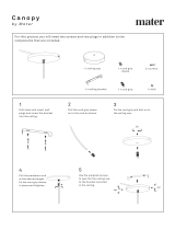 mater Canopy Terho Pendant Light User manual
-
-
-
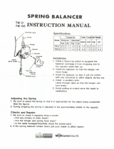 Tigon TW-0 Spring Balancer, Tool Balancer User manual
-
 Blue Hawk 55427 User manual
-
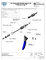 T & S Brass & Bronze Works MV-3516-24-RK Datasheet


