Page is loading ...

REVOLUTION™ 8 & 12 FEEDER
Variable Brood Feeding System
Installation and Operators Manual
MF1749AOctober 2003

Chore-Time Warranty REVOLUTION™ 8 & 12 FEEDER Variable Brood Feeding System
1
MF1749A
Chore-Time Equipment (“Chore-Time”) warrants each new Chore-Time product manufactured by it to be free
from defects in material or workmanship for one year from and after the date of initial installation by or for the
original purchaser. If such a defect is found by the Manufacturer to exist within the one-year period, the
Manufacturer will, at its option, (a) repair or replace such product free of charge, F.O.B. the factory of
manufacture, or (b) refund to the original purchaser the original purchase price, in lieu of such repair or
replacement. Labor costs associated with the replacement or repair of the product are not covered by the
Manufacturer.
Conditions and Limitations
1. The product must be installed by and operated in accordance with the instructions published by the
Manufacturer or Warranty will be void.
2. Warranty is void if all components of the system are not original equipment supplied by the Manufacturer.
3. This product must be purchased from and installed by an authorized distributor or certified representative
thereof or the Warranty will be void.
4. Malfunctions or failure resulting from misuse, abuse, negligence, alteration, accident, or lack of proper
maintenance shall not be considered defects under the Warranty.
5. This Warranty applies only to systems for the care of poultry and livestock. Other applications in industry
or commerce are not covered by this Warranty.
The Manufacturer shall not be liable for any Consequential or Special Damage which any purchaser may suffer
or claim to suffer as a result of any defect in the product. “Consequential” or “Special Damages” as used herein
include, but are not limited to, lost or damaged products or goods, costs of transportation, lost sales, lost orders,
lost income, increased overhead, labor and incidental costs and operational inefficiencies.
THIS WARRANTY CONSTITUTES THE MANUFACTURER’S ENTIRE AND SOLE WARRANTY AND
THIS MANUFACTURER EXPRESSLY DISCLAIMS ANY AND ALL OTHER WARRANTIES,
INCLUDING, BUT NOT LIMITED TO, EXPRESS AND IMPLIED WARRANTIES AS TO
MERCHANTABILITY, FITNESS FOR PARTICULAR PURPOSES SOLD AND DESCRIPTION OR
QUALITY OF THE PRODUCT FURNISHED HEREUNDER.
Chore-Time Distributors are not authorized to modify or extend the terms and conditions of this Warranty in any
manner or to offer or grant any other warranties for Chore-Time products in addition to those terms expressly
stated above. An officer of CTB, Inc. must authorize any exceptions to this Warranty in writing. The Manufacturer
reserves the right to change models and specifications at any time without notice or obligation to improve previous
models.
Effective: October 2003
Chore-Time Equipment
A Division of CTB, Inc.
P.O. Box 2000 • Milford, Indiana 46542-2000 • U.S.A.
Phone (574) 658-4101 • Fax (877) 730-8825
Email: [email protected] • Internet: http//www.ctbinc.com
Thank You
The employees of Chore-Time Equipment would like to thank your for your recent Chore-Time purchase. If a
problem should arise, your Chore-Time distributor can supply the necessary information to help you.
Chore-Time Warranty

Contents
Topic Page
MF1749A
2
Chore-Time Warranty . . . . . . . . . . . . . . . . . . . . . . . . . . . . . . . . . . . . . . . . . . . . . . . . . . . . . . . . . . . . 1
About This Manual. . . . . . . . . . . . . . . . . . . . . . . . . . . . . . . . . . . . . . . . . . . . . . . . . . . . . . . . . . . . . . . 4
Safety Information . . . . . . . . . . . . . . . . . . . . . . . . . . . . . . . . . . . . . . . . . . . . . . . . . . . . . . . . . . . . . . . 4
Safety Instructions . . . . . . . . . . . . . . . . . . . . . . . . . . . . . . . . . . . . . . . . . . . . . . . . . . . . . . . . . . . . . . . 5
Follow Safety Instructions . . . . . . . . . . . . . . . . . . . . . . . . . . . . . . . . . . . . . . . . . . . . . . . . . . . . . . . . . . . . . . 5
Decal Descriptions . . . . . . . . . . . . . . . . . . . . . . . . . . . . . . . . . . . . . . . . . . . . . . . . . . . . . . . . . . . . . . . . . . . . 5
DANGER: Moving Auger. . . . . . . . . . . . . . . . . . . . . . . . . . . . . . . . . . . . . . . . . . . . . . . . . . . . . . . . . . . 5
DANGER: Electrical Hazard . . . . . . . . . . . . . . . . . . . . . . . . . . . . . . . . . . . . . . . . . . . . . . . . . . . . . . . . 5
CAUTION: . . . . . . . . . . . . . . . . . . . . . . . . . . . . . . . . . . . . . . . . . . . . . . . . . . . . . . . . . . . . . . . . . . . . . . 5
General. . . . . . . . . . . . . . . . . . . . . . . . . . . . . . . . . . . . . . . . . . . . . . . . . . . . . . . . . . . . . . . . . . . . . . . . . 5
Support Information . . . . . . . . . . . . . . . . . . . . . . . . . . . . . . . . . . . . . . . . . . . . . . . . . . . . . . . . . . . . . . . . . . . 5
Planning the Suspension System . . . . . . . . . . . . . . . . . . . . . . . . . . . . . . . . . . . . . . . . . . . . . . . . . . . . 7
General Installation Information . . . . . . . . . . . . . . . . . . . . . . . . . . . . . . . . . . . . . . . . . . . . . . . . . . . 8
Laying out the Suspension System . . . . . . . . . . . . . . . . . . . . . . . . . . . . . . . . . . . . . . . . . . . . . . . . . . 8
Installing the Suspension System . . . . . . . . . . . . . . . . . . . . . . . . . . . . . . . . . . . . . . . . . . . . . . . . . . . 9
Power Lift Winch Installation. . . . . . . . . . . . . . . . . . . . . . . . . . . . . . . . . . . . . . . . . . . . . . . . . . . . . . . . . . . . 9
Installing the Main Winch Cable . . . . . . . . . . . . . . . . . . . . . . . . . . . . . . . . . . . . . . . . . . . . . . . . . . . . . . . . .10
Screw Hook Installation . . . . . . . . . . . . . . . . . . . . . . . . . . . . . . . . . . . . . . . . . . . . . . . . . . . . . . . . . . . . . . . .11
Ceiling Hook Installation . . . . . . . . . . . . . . . . . . . . . . . . . . . . . . . . . . . . . . . . . . . . . . . . . . . . . . . . . . . . . . .12
Drop Installation . . . . . . . . . . . . . . . . . . . . . . . . . . . . . . . . . . . . . . . . . . . . . . . . . . . . . . . . . . . . . . . . . . . . . .13
Feeder Pan Assembly . . . . . . . . . . . . . . . . . . . . . . . . . . . . . . . . . . . . . . . . . . . . . . . . . . . . . . . . . . . . 14
Installing the pivot bracket. . . . . . . . . . . . . . . . . . . . . . . . . . . . . . . . . . . . . . . . . . . . . . . . . . . . . . . . . . . . . .16
Feeder line planning . . . . . . . . . . . . . . . . . . . . . . . . . . . . . . . . . . . . . . . . . . . . . . . . . . . . . . . . . . . . . 17
Feeder Line Assembly and Suspension. . . . . . . . . . . . . . . . . . . . . . . . . . . . . . . . . . . . . . . . . . . . . . 19
Actuator Tube Assembly . . . . . . . . . . . . . . . . . . . . . . . . . . . . . . . . . . . . . . . . . . . . . . . . . . . . . . . . . . . . . . .19
Feeder Pan and Tube Assembly Process . . . . . . . . . . . . . . . . . . . . . . . . . . . . . . . . . . . . . . . . . . . . . . . . . . .19
Assemble and Suspend the Feeder Line . . . . . . . . . . . . . . . . . . . . . . . . . . . . . . . . . . . . . . . . . . . . . . . . . . . .20
Installing the End Control, Boot Assembly, and Auger . . . . . . . . . . . . . . . . . . . . . . . . . . . . . . . . . . . . . . . .22
Auger Installation . . . . . . . . . . . . . . . . . . . . . . . . . . . . . . . . . . . . . . . . . . . . . . . . . . . . . . . . . . . . . . . . .23
Auger Brazing . . . . . . . . . . . . . . . . . . . . . . . . . . . . . . . . . . . . . . . . . . . . . . . . . . . . . . . . . . . . . . . . . . . .27
Installing spring brackets:. . . . . . . . . . . . . . . . . . . . . . . . . . . . . . . . . . . . . . . . . . . . . . . . . . . . . . . . . . . . . . .28
Installing actuator wire: . . . . . . . . . . . . . . . . . . . . . . . . . . . . . . . . . . . . . . . . . . . . . . . . . . . . . . . . . . . . . . . .31
Installing the actuator cable: . . . . . . . . . . . . . . . . . . . . . . . . . . . . . . . . . . . . . . . . . . . . . . . . . . . . . . . . .32
Installing travel stops: . . . . . . . . . . . . . . . . . . . . . . . . . . . . . . . . . . . . . . . . . . . . . . . . . . . . . . . . . . . . . .33
Anti-Roost Installation . . . . . . . . . . . . . . . . . . . . . . . . . . . . . . . . . . . . . . . . . . . . . . . . . . . . . . . . . . . . . . . . .34
Electro-guard Operation . . . . . . . . . . . . . . . . . . . . . . . . . . . . . . . . . . . . . . . . . . . . . . . . . . . . . . . . . . . . . . . .37
Mid-Line Control . . . . . . . . . . . . . . . . . . . . . . . . . . . . . . . . . . . . . . . . . . . . . . . . . . . . . . . . . . . . . . . 38
Feeder Management and Operation . . . . . . . . . . . . . . . . . . . . . . . . . . . . . . . . . . . . . . . . . . . . . . . . 40
Initial Start-up of the Feeding System . . . . . . . . . . . . . . . . . . . . . . . . . . . . . . . . . . . . . . . . . . . . . . . . . . . . .40
General Operation of the Rev. 8 and 12 Feeders . . . . . . . . . . . . . . . . . . . . . . . . . . . . . . . . . . . . . . . . . . . . .41
REVOLUTION™ Feeding System Operation Guide . . . . . . . . . . . . . . . . . . . . . . . . . . . . . . . . . . . . . . . . .42
End Control and Mid Line Control Pans . . . . . . . . . . . . . . . . . . . . . . . . . . . . . . . . . . . . . . . . . . . . . . . . . . .43
Controlling the Feeders (optional equipment) . . . . . . . . . . . . . . . . . . . . . . . . . . . . . . . . . . . . . . . . . . . . . . .43

Contents - continued
Topic Page
3
MF1749A
Maintenance . . . . . . . . . . . . . . . . . . . . . . . . . . . . . . . . . . . . . . . . . . . . . . . . . . . . . . . . . . . . . . . . . . . 44
Floor Feeding System Maintenance . . . . . . . . . . . . . . . . . . . . . . . . . . . . . . . . . . . . . . . . . . . . . . . . . . . . . . .44
Gear Head Maintenance . . . . . . . . . . . . . . . . . . . . . . . . . . . . . . . . . . . . . . . . . . . . . . . . . . . . . . . . . . . . . . . .44
SENSOR PLUS Sensor Switch Adjustment for Control Units . . . . . . . . . . . . . . . . . . . . . . . . . . . . . . . . . .45
Feeder Line . . . . . . . . . . . . . . . . . . . . . . . . . . . . . . . . . . . . . . . . . . . . . . . . . . . . . . . . . . . . . . . . . . . . . . . . . .45
Power Lift Winch Maintenance . . . . . . . . . . . . . . . . . . . . . . . . . . . . . . . . . . . . . . . . . . . . . . . . . . . . . . . . . .46
Trouble Shooting the Floor Feeding System . . . . . . . . . . . . . . . . . . . . . . . . . . . . . . . . . . . . . . . . . 47
Wiring Diagrams . . . . . . . . . . . . . . . . . . . . . . . . . . . . . . . . . . . . . . . . . . . . . . . . . . . . . . . . . . . . . . . 48
Internal Wiring End Control . . . . . . . . . . . . . . . . . . . . . . . . . . . . . . . . . . . . . . . . . . . . . . . . . . . . . . . . . . . . .48
SENSOR PLUS Control Wiring Diagram . . . . . . . . . . . . . . . . . . . . . . . . . . . . . . . . . . . . . . . . . . . . . . . . . .48
Parts Listing . . . . . . . . . . . . . . . . . . . . . . . . . . . . . . . . . . . . . . . . . . . . . . . . . . . . . . . . . . . . . . . . . . . 50
200# Hopper Components . . . . . . . . . . . . . . . . . . . . . . . . . . . . . . . . . . . . . . . . . . . . . . . . . . . . . . . . . . . . . .50
100 # Hopper Components . . . . . . . . . . . . . . . . . . . . . . . . . . . . . . . . . . . . . . . . . . . . . . . . . . . . . . . . . . . . . .51
Hopper Mount Bracket (Optional) . . . . . . . . . . . . . . . . . . . . . . . . . . . . . . . . . . . . . . . . . . . . . . . . . . . . . . . .52
Single Boot Components Part No. 6822. . . . . . . . . . . . . . . . . . . . . . . . . . . . . . . . . . . . . . . . . . . . . . . . . . . .52
Twin Boot Components Part No. 6824. . . . . . . . . . . . . . . . . . . . . . . . . . . . . . . . . . . . . . . . . . . . . . . . . . . . .53
Feeder Line Components . . . . . . . . . . . . . . . . . . . . . . . . . . . . . . . . . . . . . . . . . . . . . . . . . . . . . . . . . . . . . . .54
Power Unit Assemblies. . . . . . . . . . . . . . . . . . . . . . . . . . . . . . . . . . . . . . . . . . . . . . . . . . . . . . . . . . . . . . . . .55
Power Unit Assembly Part Numbers:. . . . . . . . . . . . . . . . . . . . . . . . . . . . . . . . . . . . . . . . . . . . . . . . . . . . . .55
Sensor Plus End Control . . . . . . . . . . . . . . . . . . . . . . . . . . . . . . . . . . . . . . . . . . . . . . . . . . . . . . . . . . . . . . . .56
Sensor Plus Mid Line Control . . . . . . . . . . . . . . . . . . . . . . . . . . . . . . . . . . . . . . . . . . . . . . . . . . . . . . . . . . .58
Actuator system . . . . . . . . . . . . . . . . . . . . . . . . . . . . . . . . . . . . . . . . . . . . . . . . . . . . . . . . . . . . . . . . . . . . . .60
2883 Power Winch . . . . . . . . . . . . . . . . . . . . . . . . . . . . . . . . . . . . . . . . . . . . . . . . . . . . . . . . . . . . . . . . . . . .61
Miscellaneous Suspension Components. . . . . . . . . . . . . . . . . . . . . . . . . . . . . . . . . . . . . . . . . . . . . . . . . . . .62
Feeder Components . . . . . . . . . . . . . . . . . . . . . . . . . . . . . . . . . . . . . . . . . . . . . . . . . . . . . . . . . . . . . . . . . . .63

REVOLUTION™ 8 & 12 FEEDER Variable Brood Feeding System About This Manual
MF1749A
4
The intent of this manual is to help you in two ways. One is to follow step-by-step in the order of assembly of your
product. The other way is for easy reference if you have questions in a particular area.
Important: Read ALL instructions carefully before starting construction.
Important: Pay particular attention to all SAFETY information.
• Metric measurements are shown in millimeters and in brackets, unless otherwise specified. “ " ” equals inches
and “ ' ” equals feet in English measurements.
Examples:
1" [25.4]
4' [1 219]
• Optional equipment contains necessary instructions for assembly or operation.
• Very small numbers near an illustration (i.e.,
1257-48) are identification of the graphic, not a part number.
Caution, Warning and Danger Decals have been placed on the equipment to warn of potentially dangerous
situations. Care should be taken to keep this information intact and easy to read at all times. Replace missing or
damaged safety decals immediately.
Using the equipment for purposes other than specified in this manual may cause personal injury and/or damage to
the equipment.
Safety–Alert Symbol
This is a safety–alert symbol. When you see this symbol on your equipment, be alert to the
potential for personal injury. This equipment is designed to be installed and operated as safely
as possible...however, hazards do exist.
Understanding Signal Words
Signal words are used in conjunction with the safety–alert symbol to identify the severity of the warning.
DANGER indicates an imminently hazardous situation which, if not avoided, WILL result in death or
serious injury.
WARNING indicates a potentially hazardous situation which, if not avoided, COULD result in death or
serious injury.
CAUTION indicates a hazardous situation which, if not avoided, MAY result in minor or moderate
injury.
About This Manual
Safety Information

REVOLUTION™ 8 & 12 FEEDER Variable Brood Feeding System Safety Instructions
MF1749A
5
Follow Safety Instructions
Carefully read all safety messages in this manual and on your equipment safety signs. Follow recommended
precautions and safe operating practices.
Keep safety signs in good condition. Replace missing or damaged safety signs.
Decal Descriptions
DANGER: Moving Auger
This decal is placed on the Panel Weldment.
Severe personal injury will result, if the electrical power is not
disconnected, prior to servicing the equipment.
DANGER: Electrical Hazard
Disconnect electrical power before inspecting or servicing equipment
unless maintenance instructions specifically state otherwise.
Ground all electrical equipment for safety.
All electrical wiring must be done by a qualified electrician in accordance
with local and national electric codes.
Ground all non-current carrying metal parts to guard against electrical
shock.
With the exception of motor overload protection, electrical disconnects and
over current protection are not supplied with the equipment.
CAUTION:
Use caution when working with the Auger—springing Auger may cause personal
injury.
Support Information
The Chore-Time REVOLUTION™ 8 and 12 Feeder Variable Brood Feeding Systems have been designed to feed
poultry. Using this equipment for any other purpose or in a way not within the operating recommendations
specified in this manual will void the warranty and may cause personal injury.
This manual is designed to provide comprehensive planning and installation information. The Table of Contents
provides a convenient overview of the information in this manual.
Safety Instructions
General
Manboot 3/98

REVOLUTION™ 8 & 12 FEEDER Variable Brood Feeding System Planning the Suspension System
MF1749A
6
1. Select the House Layout.
A. Optional Mid Line Controls may be used for partial house brooding. See “Figure 1. Component location
diagram for systems up to 400 feet [122 m]. (Top View).” on page 6.
Figure 1. Component location diagram for systems up to 400 feet [122 m]. (Top View).
B. Systems with line lengths over 400’ [122 m] should be split in the center, as shown in “Figure 2.
Component location diagram for systems over 400 feet [122 m]. (Top View).” on page 6. This will
reduce auger running time and eliminate the need for Mid-Line Controls for partial house brooding.
Figure 2. Component location diagram for systems over 400 feet [122 m]. (Top View).
2. Determine the Feed Bin location.
3. Determine the Brood Curtain location.
4. Determine number of brood actuator and location.
5. Determine the location for the End Control Pans, and if used the Mid Line Control Pans. The
Feeder Control Pans should be at least 10’ [3 m] from the Wall or Brood Curtain.
6. Determine the distance to the Feeder Line from the Side Wall.
7. Determine the distance from the Feed Hoppers to the End Wall for a Straight Line Feeding System.
Planning the Suspension System

REVOLUTION™ 8 & 12 FEEDER Variable Brood Feeding System General Installation Information
MF1749A
7
Please read the installation instructions in this manual prior to beginning the installation. This manual provides
the necessary information on the installation, operation, and maintenance of the Chore-Time feeding equipment
you have purchased.
The suspension, hopper assembly, feeder line installation, and anti-roost installation is the same for each system,
except where noted otherwise. Please pay particularly close attention to insure proper assembly and installation
of the equipment.
The REVOLUTION™ 8 and 12 FEEDER Control Units use a 348 RPM. Gearhead, delivering approximately
17 lbs [7.7 kg] per minute. This rating is based on feed with a density of 40 lbs per cubic foot [640 kg per cubic
meter].
Single phase 60 Hz and single and three phase 50 Hz Power Units are available for the Rev. 12 and 8 Feeders.
Systems up to 300' [91 m] require 1/3 HP. Power Units. Systems over 300' [91 m] require 1/2 HP. Power Units.
1. Select the Suspension type.
A. For systems up to 350' [107 m]
Figure 3. Suspension for systems up to 350’ [107 m]
General Installation Information
Laying out the Suspension System
1255-71 1/2001
4)
Swivel Pulley
5)
Full Line Suspension Kit
7)
1'
[30 cm]
4)
Swivel Pulley
6)
Power Lift Winch
8)
3'
[1 m]
1)
Hopper Support
2)
Power Lift Winch Support
3)
Roof Trusses

REVOLUTION™ 8 & 12 FEEDER Variable Brood Feeding System Installing the Suspension System
MF1749A
8
B. For systems over 350' [107 m]
Figure 4. Suspension for systems over 350’ [107 m]
2. Locate the Power Lift Winch. The Power Lift Winch requires a support that will span, in a wood
frame house at least 3 rafters, and in a steel frame house at least 2 rafters.
3. Locate the Power Unit and Feed Hopper. Special support is required at each Power Unit and Feed
Hopper location.
4. Determine the Drop Location and length. Suspension systems are based on ceiling heights of 14'
[4.3 m] with suspension drop points every 8' [2.4 m]. DO NOT EXCEED 10' [3 m] BETWEEN
SUSPENSION DROPS.
5. Determine the location for Screw Hooks. Mark a straight line or use cable to locate Screw Hooks.
Use the offset of Screw Hooks where necessary.
Power Lift Winch Installation
1. Bolt the Power Winch, fully assembled, to the
Power Lift Winch Support, either a 2'' x 8''
[50x200 mm] board that will span at least 3
rafters or a 3/8'' [9.5 mm] thick steel plate
welded to two pieces angle iron that are each
long enough to span at least 2 rafters, using
5/16-18 hardware supplied in the Hardware
Package. The brake mechanism will extend
toward one side.
Install a Cable Hook, supplied in
Hardware Package, between the
mounting bolt and Power Winch
frame, as shown in figure 6.Figure
6. Assembling the Power Winch to
the Rafters
Installing the Suspension System
1) Full Line Suspension Kit
12) Hopper
Support Cable
6) Small Pulley
and Screw Hook
3) Large Pulley
with Double Clamps
10) Power
Lift Winch
9) Lift Distance
+ 2' [61 cm]
8) Lift
Distance
7) 3'
[91.4 cm]
6) Small Pulley
and Screw Hook
1255-72 9/200
0
11) Drop must be
within 1' [30.5 cm]
of Hopper
2) Hopper Support
4) Power Lift Winch Support
5) Roof Trusses
1255-115 2/2001
Angle Iron
3/8" [9.5 mm]
Thick Steel Plate
Figure 5. Optional Power Lift Winch support detail
4) 5/16-18 Bolt,
Washer, and
Lock Nut
2) Cable Hook
1) Power Lift Winch
3) Power Lift
Winch Support
1255-79 1/2001
Figure 6. Assembling the Power Winch to the Rafters

REVOLUTION™ 8 & 12 FEEDER Variable Brood Feeding System Installing the Suspension System
MF1749A
9
2. Attach the Power Lift Winch Support (with the Power Winch secured) to the ceiling at the center of
the feeder line. See Figure 7. The Power Lift Winch Support must be parallel to the feeder line and
must span at least 3 rafters in a wood frame house and 2 rafters in a steel frame house.
If the hopper is located at the center of the feeder line, locate the Power Winch a few feet offset from
the center of the feeder line. However, the Winch Drum must be directly in line with where the main
cable is to be installed.
Installing the Main Winch Cable
The Suspension Systems are based on ceiling heights of 14' [4.3 m] with Suspension Drop points every 8' [2.4 m].
DO NOT EXCEED 10' [3 m] BETWEEN SUSPENSION DROPS. Refer to suspension section in this manual for
installation details.
Adequate overhead structure must be provided to support the weight of the feeders, hoppers, power units, etc. The
Suspension System is the same for the Rev. 12 and 8 Feeders. The type of installation required depends on the
feeder line length.
IMPORTANT: Special support is required at each Hopper
location.
• Power Unit Locations: The Feeder Line must be supported within
3' [.9 m] of the Power Unit. This is in addition to the required
Power Unit suspension. If the Control Unit or Hopper does not come
out directly under a truss, fasten a pulley to a 2'' x 8'' [50 x 200 mm]
board or steel angle that will span 2 trusses and is capable of
supporting 300 lbs [136 kg] for the Hopper and 75 lbs [34 kg] for
the Control Unit.
• Feed Hopper Locations: The Feeder Line must be supported
within 1' [30 cm] of the Feed Hopper. This is in addition to the
required Feeder Hopper suspension. After determining the type of
suspension system required, decide where the Feeder Line is to be installed. Mark a straight line on the
ceiling or rafters the full length of the Feeder Line. Use a string, chalk line, or the winch cable, temporarily
attached with staples, to mark the line. Center the line directly over where the Feeder Line is to be installed.
3. Extend the 3/16" [5 mm] Main Winch Cable the full length of the feeder line. Attach the cable
temporarily to the ceiling with nails, staples, or some type of fasteners. Figure 9“Figure 9. Double
back arrangement for feed lines over 350' [107 m]” on page 9shows a double back arrangement
for feed lines over 350' [107 m].
1) Power Lift
Winch Support
2) Rafte
r
Figure 7. Mounting the Power Lift Winch and Support to the Rafters
1255-113 1/2001
Figure 8. Full Line Suspension Kit
1255-63 4/2001
Double Clamp these areas
Figure 9. Double back arrangement for feed lines over 350' [107 m]

REVOLUTION™ 8 & 12 FEEDER Variable Brood Feeding System Installing the Suspension System
MF1749A
10
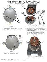
4. Route the cable through the Winch
Drum Relief located near the bottom
of the drum. Tighten the set screw to
anchor the cable to the drum. See
figure 10.“Figure 10. Attaching the
Cable to the Power Winch” on
page 10
5. Turn the winch drum one full revolution. Guide the
cable against the flange at the bottom of the winch
drum. The cable must not wrap over itself on the
drum, but should be wrapped as close as possible to
each previous wrap. See figure 11.“Figure 11.
Power Winch Drum Rotation” on page 10
Screw Hook Installation
The recommended distance between the
drops for the Rev. 12 & 8 FEEDER is 8’
[2.4 m] on center. Do not exceed 10’ [3 m]
spacing on drop lines.
If the distance raised is greater than the
distance between the drop spacings, offset
the hooks 3" [7.6 cm] to each side of the
line to prevent the cable clamps from
catching the pulleys. See Figure
12.“Figure 12. Drop Line Off Set Detail”
on page 10
Screw the hook into the truss
the full length of the threads
to prevent bending.
The openings of the screw
hooks must be pointed away
from the direction of travel
when the Power Winch raises
the feeder line. See Figure
13.“Figure 13. Screw Hook
Installation” on page 10
1255-80 1/2001
1) Winch Drum Relie
f
with Set Screw
2) 3/16" Main
Winch Cable
3) Drum Direction
of Rotation
Figure 10. Attaching the Cable to the Power Winch
1255-81 9/2000
1) Drum Direction
of Rotation
Figure 11. Power Winch Drum Rotation
1255-70 1/2001
1) 3/16" [5 mm]
Main Winch Cable
3) Screw Hook or Ceiling Hook Location
2) 3/32" [2 mm]
Drop Cable
4) Distance
of Cable
Travel
5) Distance Feeder
is to be Raised
6) 3" [7.6 cm]
Offset
Figure 12. Drop Line Off Set Detail
1) Screw Hook
opening facing
opposite direction
of travel
2) Winch End
(Direction of Travel)
3) 3/16" Main
Winch Cable
4) 3/32" Drop Cable
1255-73 1/2001
Figure 13. Screw Hook Installation

REVOLUTION™ 8 & 12 FEEDER Variable Brood Feeding System Installing the Suspension System
MF1749A
11
Ceiling Hook Installation
The ceiling hook may be used in a variety of installations. Depending on your ceiling or rafter type, install the
Ceiling Hooks as shown in Figures 14 - 17.
Steel Truss Installations
Steel Truss Welded Installations
Wood Truss Installations
1
2
5
5
-
7
4
9
/
2
0
0
0
1) Secure Ceiling Hook to truss
using self-drilling screws
through opposite holes
2) Cable Travel
Figure 14. Steel Truss Ceiling Bracket Installation
1255-76 9/2000
2) Cable Travel
1) Weld Ceiling Bracket
to truss here
1) Weld Ceiling Bracket
to truss here
Figure 15. Welded Steel Truss Ceiling Bracket Installation
1255-77 3/2001
1) Secure Ceiling Bracket to truss
using a 1/4" lag screw (not supplied)
through the center hole
2) Cable Travel
Figure 16. Wood Truss Ceiling Bracket Installation

REVOLUTION™ 8 & 12 FEEDER Variable Brood Feeding System Installing the Suspension System
MF1749A
12
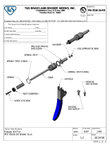
6. After securing the Ceiling Hook to the truss, slide
the hook of a Swivel Pulley into the slot, as shown
in Figure 17“Figure 17. Pulley Installation” on
page 12.
Drop Installation
Refer to“Figure 12. Drop Line Off Set Detail” on page 10Figure 13 on page 10.
1. Attach a 3004 Pulley to each hook.
2. Thread the end of the 3/32" or 1/8" cable through the pulley toward the winch. Clamp this end to the
3/16" winch cable about 6" [150 mm] from the last pulley, using a 3/16" cable clamp. See
applicable figure; Figure 13 or 17.
3. Allow enough cable length for installation of the Adjustment Leveler.
Sufficient cable is included to provide "throwbacks" on drops located beneath and near the winch.
Figure 18 shows a "throwback" cable arrangement.
4. Begin installing suspension drops at the winch and proceed to the ends of the feeder line.
Keep the main cable tight between drops. It may be necessary to hang a weight on the end of the
cable to maintain tension on the line.
1255-78 1/2001
1) Wood Truss
2) Ceiling Bracket
3) 1/4" Lag Screw
4) Swivel Pulley
5) 3/32" Drop Cable
Figure 17. Pulley Installation
967-4 2/01
Figure 18. "Throwback" cable arrangement

REVOLUTION™ 8 & 12 FEEDER Variable Brood Feeding System Feeder Pan Assembly
MF1749A
13
All feeders assemble in the same manor. Refer to Figure 20 and 21. The inner cone must turn freely. Align the
threads on the outside of the adjustment cone and the grill cap. Turn the cone assembly into the grill cap.
Continue turning grill until the pointer lines up with the #3 position. See Figure 20. Turn the grill and cone
assembly over place the feeder pan on the grill, turn the pan clockwise until the lock engages. Assemble the
remaining Feeders.Assembly Box Construction for Rev. 12 and 8 Feeders
Figure 19
This information and assembly only applies to Rev. 12 and 8 feeder installations.
Chore-Time recommends building an assembly box to aid in assembling the Rev. 12 and 8
feeders for pan assembly procedure option 1(see next page).
To build the assembly box for the Rev. 12 feeder, use a 16" X 17" piece of plywood and two
14-1/2" and two 17" long pieces of 2 x 12.
1. Cut a piece of 3/4" plywood 16" X 17". See Figure 19A.
2. Center the grill on the 16" X 17" piece of plywood. Use a pencil and draw around the in
side edge of the grill as shown in Figure 19B.
Mark a "V" at each strut location.
3. Remove the grill.
Use a 7/8" spade bit to drill a hole at each strut location, as shown in Figure 19C.
4. Use a sabre saw to cut along the inside circle, between the 7/8" holes. See Figure 19D.
5. Use (2) 14-1/2" and (2) 17" 2 x 12’s to construct the box sides. Nail the 3/4" plywood
fixture to the box. See Figure 19E.
It is important to use at least 12" sides for the box. Smaller lumber will not allow sufficient
depth for the grill to be placed in the box face down.
Figure 19F shows how the grill should fit down in assembly box. NOTE: Board is cut away
for clarity only.
Feeder Pan Assembly
Figure 19A Figure 19B Figure 19C
Figure 19D Figure 19E Figure 19F

REVOLUTION™ 8 & 12 FEEDER Variable Brood Feeding System Feeder Pan Assembly
MF1749A
14
Pan Assembly Procedure for Rev. 12 and 8 Feeders (Option 1)
1. Place a Grill in the pan assembly box fixture.
2. Install cone assembly in the grill, Check fit, correct, grill and cone should be snug,
incorrect if grill and cone have free motion.
3 Place the feed pan in the grill ring, The pan must be fully seated in the grill then rotate
the pan until the pan locks in their grill
Pan Assembly Procedure for Rev. 12 and 8 Feeders (Option 2)
1) Place cone assembly on a flat surface and set grill over the cone.
2) Rotate the grill until the threads are started.
3) Continue rotating the grill until you reach position 3.
4) Turn the assembly over then install the pan by rotating the pan until it latches.
Adjustment of
feed level to #3 position.
Figure 21. Pan assembly option 2
support cone and the grill
Align the threads on the
cap.
Adjustment of feed level
to #3 position.
Figure 20. Pan Assembly
Option 1

REVOLUTION™ 8 & 12 FEEDER Variable Brood Feeding System Feeder Pan Assembly
MF1749A
15
Installing the pivot bracket.
The pivot bracket will be installed using
a #10 screw. The pivot bracket should be
installed with the open channel outward
from the feeder.
Do not over tighten the screw! Pivot
bracket must turn freely!
DO NOT OVER TIGHTEN THE SCREW!
PIVET BRACKET MUST TURN FREELY!
1749-23 03/03
PIVET BRACKET
TWIN HELIX SCREW
Figure 22. Installing the pivot bracket

REVOLUTION™ 8 & 12 FEEDER Variable Brood Feeding System Feeder line planning
MF1749A
16
F
i
g
u
r
e
2
2
T
y
p
i
c
a
l
b
u
i
l
d
F
F
Figure 23. Typical building layout
Feeder line planning
H
O
P
P
E
R
E
N
D
E
N
D
C
O
N
T
R
O
L
Actuator
Placement
Actuator
Placement
Actuator
Placement
Actuator
Placement
5 Tubes
5 Tubes
6 Tubes6 Tubes
6 Tubes
6 Tubes
9 Foot 4 Hole tube
10 Foot 4 Hole tube
12 Foot 4 Hole tube
4 Tubes
1 Tube
1 Tube
1 Tube
5 Tubes
12 Foot 5 Hole tube
1 Tube
Brood Area
Layout
f
or actuator p
l
acement
Layout figured on 60 pans in brood area.
Figure 24. Pan orientation on tube
Determine the feeder layout you will be
installing. Assemble the feed pans on
the tube according to the layout above.
Assemble the correct number of tubes
with the pivot bracket on the correct
side of the pan. To ensure the pivot
bracket is assembled on the correct side
stand over the actuator looking at the
belled end of the tube. The pans in front
of you will have the pivot bracket on the
Left, while the pans behind you will have the
the pivot bracket on the right.
Example for a 9 foot tube you will assemble 6
tubes with the pivot bracket on the left side
and 6 tubes with the pivot bracket on the right
side. For a 9 foot tube system the tube where
the actuator will be mounted will have two
pans on the left and two pans on the right
PIVOT
PIVOT
PLACE ACTUATOR IN THE
CENTER OF THE BROOD PANS

REVOLUTION™ 8 & 12 FEEDER Variable Brood Feeding System Feeder line planning
MF1749A
17
Below is an overview of the feeder installed with the spring brackets and actuator wire installed. It is very
important that the pans be installed with the pivot bracket on the correct side!!!
Figure 25. Feeder layout
Figure 26. Pivot Bracket
30 PANS MAX
30 PANS MAX
Terminal spring brackets.
Tail end of each actuator.
To Actuator
To Actuator

REVOLUTION™ 8 & 12 FEEDER Variable Brood Feeding System Feeder Line Assembly and Suspension
MF1749A
18
Actuator Tube Assembly
Install the actuator in the center of the actuator tube. Using the two half clamp and four 1/4-20 X 2.5 hex bolt
and four 1/4-20 hex flange nut. Attach the Actuator on the tube. (The Actuator handle should be to the center of
the house).
Figure 27. Actuator installation
Feeder Pan and Tube Assembly Process
1. Slide one Feeder Pan Assembly per hole onto the auger tubes.
IMPORTANT: Install all the feeders on the tubes in the same orientation.
When sliding the feeders on the tubes, make sure the pivot bracket are on the same side of the tube.
2. Rotate the auger tubes so that the seam is down, this holds the Pan Assemblies in place on the tubes.
See Figure 28.
Figure 28. Assemble Feeders on tubes
You will assemble half the tubes with the pivot bracket on the left side and half on the right side.
The tubes with the actuator mounted will have different pans on the same tube.
Example: a 9 foot tube will have two pans on the left side and two tubes on the right side
a ten foot 4 hole will have one pan on the left and three pans on the right.
Feeder Line Assembly and Suspension
Note:
Close chick hole if necessary
using a tube closure kit.
Supplied with Kit.
1) With the seam of the
feeder tube up slide the
pan assembly on the feeder
tube. Position one (1) feeder
pan over each hole on the
feeder tube.
2) Rotate the feeder tube after the
feeder pan assemblies are
in place. This will lock the
feeder pan assemblies in place.

REVOLUTION™ 8 & 12 FEEDER Variable Brood Feeding System Feeder Line Assembly and Suspension
MF1749A
19
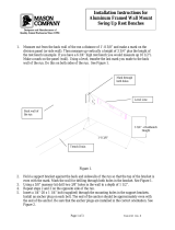
Assemble and Suspend the Feeder Line
1. The actuator, auger tubes and feeders may be laid out end to end in approximately the final location
of the line. The belled end of each tube should be toward the (3) Hopper end of the line.
See Figure 29. Be sure to have the correct number of right and left sided tubes with the actuator in
the center (The actuator handle should be to the center of the house). One actuator handles up to 60
feeder pans with the actuator placed dividing the (60) pans approximately in half.
2. Connect the individual feeder tubes together by inserting the straight end of one tube as far as
possible into the (2) belled end of the next tube. The last Feeder Tube before the (1) End Control
Pan or Mid Line Control pan must be a Control Tube.
3. To achieve total feed drop out all
along the system, the Chore-Time
Logo should be centered at the crown
of the tubes and all the Hangers
should be installed as shown in
Figure 30.
4. Place a Tube Clamp Assembly or
Clamp/Anti-Roost Bracket at each
joint. Figure 31 shows the standard
Clamp and Clamp/Anti-Roost Bracket.
Systems using 9’ or 10’ tubes require a
Clamp/Anti-Roost Bracket at every
fifth joint.
Systems using 12’ tubes require a
Clamp/Anti-Roost Bracket at every
fourth joint. All other joints in the
system use the standard Tube Clamp
Assembly.
Figure 29 Attaching Feeder Tube Assemblies
1255-84 4/2001
1) Tube Seam
3) Hanger
2) Auger Tube
4) Chore-Time Logo
Figure 30. Hanger Installation
1) Tube Clamp
1255-121 2/2001
2) Anti-Roost Bracket
Figure 31. Tube Clamp and Tube Clamp with Anti-Roost Bracket
/