Page is loading ...

Program Type Low Temperature
Incubator/Constant Temperature
Incubator
Model INC820
Instruction Manual
Second edition
● Thank you very much for purchasing this Yamato
Scientific Program Type Low Temperature Incubator
/Constant Temperature Incubator Model INC820.
● Please read the “Operating Instructions” and
“Warranty” before operating this unit to assure proper
operation. After reading these documents, be sure to
store them securely together with the “Warranty” at a
handy place for future reference.
Warning: Before operating the unit, be sure to read
carefully and fully understand important
warnings in the operating instructions.
Yamato Scientific Co., Ltd.
This paper has been printed on recycled paper.


Contentes
1. Safety precautions.................................................................... 1
Explanation of pictograms ............................................................. 1
List of symbols ....................................................................... 2
Warning・Cautions ................................................................... 3
2. Before operating the unit .............................................................. 4
Precautions when installing the unit ..................................................... 4
Installation method and precautions ..................................................... 8
About defrosting of the cooler ......................................................... 10
About the power failure compensation operation ......................................... 10
3. Names and functions of parts ......................................................... 11
Main unit ........................................................................... 11
Lower stage bath Operation panel ................................................... 12
Lower stage bath Description of characters ............................................ 14
Upper stage bath Operation panel ................................................... 15
Upper stage bath Description of characters ............................................ 16
4-1. Operating procedures(lower stage) ................................................ 17
Lower stage bath List of operation modes and functions ................................. 17
Lower stage bath Overheat preventive device setting .................................... 20
Lower stage bath Operating procedures(fixed value operation) ......................... 21
Lower stage bath Operating procedures(Quick auto stop operation).................... 22
Lower stage bath Operating procedures(auto stop operation) .......................... 23
Lower stage bath Operating procedures(
auto start operation) .......................... 25
Lower stage bath Operating procedures(making a program) ........................... 27
Lower stage bath Operating procedures(program repeat operation) ..................... 32
Lower stage bath Program preparation sheet........................................... 33
Lower stage bath Useful functions(calibration offset function) .......................... 35
4-2. Operating procedures(upper stage) ................................................ 37
Upper stage bath List of operation modes and functions ................................. 37
Upper stage bath Overheat preventive device setting .................................... 40
Upper stage bath Operating procedures(fixed value operation) ......................... 41
Upper stage bath Operating procedures(Quick auto stop operation).................... 42
Upper stage bath Operating procedures(Quick auto stop operation).................... 43
Upper stage bath Operating procedures(auto stop operation) .......................... 44
Upper stage bath Operating procedures(auto start operation) .......................... 46
Upper stage bath Useful functions(calibration offset function) .......................... 48
5. Handling precautions ................................................................50
6. Maintenance........................................................................ 52
Daily inspection/maintenance.......................................................... 52
7. When the unit is not to be used for a long time or when disposing .......................... 53
8. When a trouble occurs
............................................................... 54
Safety devices and error codes ........................................................ 54
Safety units and error codes........................................................... 55

9. After sales service and warranty ....................................................... 56
When requesting a repair ............................................................. 56
10. Specifications...................................................................... 57
11. Wiring diagram..................................................................... 58
12. Replacement part table.............................................................. 59
13. List of dangerous materials .......................................................... 60
14. Standard installation manual ......................................................... 61

1
1. Safety precautions
Explanation of pictograms
About pictograms
A
variety of pictograms are indicated in this operating instruction and on
products for safe operation. Possible results from improper operation
ignoring them are as follows.
Be sure to fully understand the descriptions below before proceeding to the
text.
Warning
Caution
Indicates a situation which may result in minor injury (Note 2) and
property damages (Note 3.)
(
Note 1
)
Serious injury means a wound, an electrical shock, a bone fracture or intoxication that ma
y
leave after effects or require hospitalization or outpatient visits for a long time.
(
Note 2
)
Minor injury means a wound or an electrical shock that does not require hospitalization o
r
outpatient visits for a long time.
(
Note 3
)
Property damage means damage to facilities, devices and buildings or other properties.
Meanings of pictograms
This pictogram indicates a matter that encourages the user to adhere to warning
(“caution” included).
Specific description of warning is indicated near this pictogram.
This pictogram indicates prohibitions
Specific prohibition is indicated near this pictogram.
This pictogram indicates matters that the user must perform
Specific instruction is indicated near this pictogram.
Indicates a situation which may result in death or serious injury (Note 1.)

2
1. Safety precautions
List of symbols
Warning
General warnings
Danger!: High
voltage
Danger!: High
temperature
Danger!: Moving
part
Danger!: Hazard
of explosion
Caution
General cautions Electrical shock! Burning!
Caution for no
liquid heating!
Caution for water
leak!
For water only
Poisonous
material
Prohibitions
General bans Fire ban
Do not
disassemble
Do not touch
Compulsions
General
compulsions
Connect ground
wire
Install levelly
Pull out the power
plug
Periodical
inspection

3
1. Safety precautions
Warning・Cautions
Warning
Never operate the unit in an atmosphere containing flammable or explosive gas
Never operate the unit in an atmosphere containing flammable or explosive gas.
Otherwise, an explosion or a fire may result since the unit is not explosion-proof.
See section “13. List of dangerous materials” on page60.
Be sure to connect the ground wire.
Connect the earth wire to an earthed outlet. When an earthed outlet is not available, use an
earthed adaptor and be sure to earth the lead wire for earthing. Otherwise, an electric shock or a
fire from electric leakage may result.
Ban on operation when an abnormality occurs
When a smoke or an unusual odor is seen or sensed, immediately turn the power supplyOFF. A
fire or an electrical shock may result.
Never use electrical power cords bundled.
When these are used bundled, they might overheat causing a fire.
Take care not to damage electrical power cords.
Avoid tightly bend, pull with a strong force or twist to prevent electrical power cords from
damaging. A fire or an electrical shock may result.
Never try to disassemble or alter the unit.
Never try to disassemble or alter the unit. A malfunction, a fire or an electrical shock may result.
Caution
When a thunder is heard.
When a thunder is heard, turn the main power off immediately. A malfunction, fire or an electrical
shock may result.

4
2. Before operating the unit
Precautions when installing the unit
1. Carefully select an installation site.
Take special care not to install the unit at a place described below:
・ Uneven surfaces or dirty surfaces
・ Where flammable gas or corrosive gas exists
・ Where the ambient temperature is 35℃ or more
・ Where temperature changes severely
・ Where humidity is high
・ Where subject to direct sunlight
・ Where vibration is severe
Install this unit at a place with spaces shown below.
15cm or
more
15cm or
more
Near side
15cm or more
1m or more
2. Install the unit on a level surface.
Install the unit on a level surface. If the whole bottom surface of the unit does not contact the
surface evenly, vibrations or noises may result. This might cause unexpected troubles or
malfunctions.
Unit Weight : approx.160 ㎏
When lifting the unit for transportation and installation, carefully handle it by at least two
people.
3. Installation
The unit might fall down or move by an earthquake or an impact resulting a personal injury.
We recommend making safety measures such as to avoid installing the unit at a place other
than busy places.

5
2. Before operating the unit
Precautions when installing the unit
4. Secure sufficient ventilation for the unit.
Do not operate the unit when its side panels and suction port and radiation port on the rear
side of the unit are blocked.
Internal temperature of the unit will rise degrading the performance and an accident, a
malfunction or a fire may result.
5. Do not operate the unit at such a place that may subject to splash.
Do not operate the unit at such a place that may subject to splash. Liquid entering the inside
may cause an accident, a malfunction, an electrical shock or a fire.
6. Never operate the unit in an atmosphere containing flammable or explosive gas.
Never operate the unit in an atmosphere containing flammable or explosive gas. Since the
unit is not explosion-proof, an arc is discharged when switching the ELB “ON” and “OFF” and
during operation and a fire or an explosion may result.
See the section “13. List of dangerous materials” on page 60 for flammable and explosive
gases.
Explosive gas
Flammable gas

6
2. Before operating the unit
Precautions when installing the unit
7. Be sure to connect the power plug to the dedicated power distribution panel or
a wall outlet.
Use a power distribution panel or a wall outlet that meets the electrical capacity of the unit.
Electrical capacity: AC100V 14A
* When the unit will not start even when you turn the Electric Leakage Breaker to “ON”, check
for low main voltage or if the unit is connected to the same power supply line as other devices
and connect it to another line if necessary.
Avoid connecting too many devices using a branching outlet or extending a wire with a cord
reel or heating function and temperature controlling function may degrade due to voltage
drop.
Do not connect the unit to any parts or lines other than a correct power supply line such as a
gas pipe, a water pipe or a telephone line.
Otherwise, an accident or a malfunction may result.
8. Handling of a power cord
Never use electrical power cords bundled. When these are used bundled, they might
overheat causing a fire.
Do not convert, forcibly bend, twist or pull the power cord. Otherwise, a fire or an electrical
shock may result.
Do not place the power cord under a desk or a chair, or sand between objects to avoid it
from being damaged.
Otherwise, a fire or an electrical shock may result.
Do not place the power cord close to a stove or other heat generating device. Sheath of the
cord may burn and result in a fire or an electrical shock.
If the power cord should be damaged (exposure of core wire or disconnection), immediately
turn the ELB off, turn the power supply off and ask your dealer to replace the cord. If the
unit is operated with a damaged power cord, a fire or an electrical shock may result.
Connect the power cord to an appropriate distribution board or wall outlet.
9. Be sure to connect the ground wire.
・ When the outlet has no earth terminal, class D earthing work will be necessary. Consult
your dealer or one of our sales offices.
・ Be sure to connect firmly to the outlet.
We recommend use of a ground type outlet
tap
When there is no ground terminal.
In this case, class D grounding work is
necessary and please consult your dealer or
our nearest sales office.
When a bipolar type outlet tap is used
Insert the ground adaptor included as an
option, into a power plug confirming the polarity
of the outlet. Connect the grounding wire
(green) of the ground adaptor to the ground
terminal on the power supply equipment.
Do not connect the grounding wire to any parts or lines other than a correct grounding
terminal such as a gas pipe, a water pipe or a telephone line.
Otherwise, an accident or a malfunction may result.
G
G
Ground type tap
Power plug
Ground wire
Bipolar
receptacle

7
2. Before operating the unit
Precautions when installing the unit
11. .Do not attempt to alter the unit 12. Do not put too many specimens.
The customer shall never attempt to alter
the unit. Otherwise a malfunction may
result.
The withstand load of a shelf board is 15kg
when the load is evenly distributed.
Put specimens dispersed.
Specimen
15kg
Shelf board
13. Do not set too many specimens. 14. Do not place an object on the
bottom plate.
Too many specimens will prevent correct
temperature control. In order to assure
temperature precision, be sure to use shelf
boards and put specimens dispersed, and
secure at least 30% of space inside the
bath.
Secure at least 30% of space
Operating the unit with placing the
specimen directly on the bottom plate of the
internal bath will prevent performance of
the product from fully exerting, increase the
internal temperature excessively and may
cause a malfunction.
Never place a specimen on the bottom
plate of the internal bath.
15. Take care during defrosting.
Put a drain pan under the end of the drain
hose during defrosting.
Note: Drain pan is not included.
Drain hose
Drain pan
Modification

8
2. Before operating the unit
Installation method and precautions
(1) Transportation of the unit
・When transporting the model INC820,
first release lock by pushing stoppers of
two caster wheels at the front of the unit
as shown in the right diagram. Check
that each caster wheel at four points
moves smoothly and start transporting
the unit.
※ When transporting over a gap, the
caster wheels may subject to an
excessive shock and be damaged. In
such a case, two or more people will be
necessary to lift the product over the
gap.
(2)
Select an installation site.
Make sure that the each caster wheel at four points rest completely on a flat surface and there
is not teetering or inclination, and then lower the caster stoppers and fix them.
(3)
Install the shelf boards for the upper stage bath.
・ The lowest shelf board for the upper stage bath has been secured with screws at the time
of factory shipping.
(The lower stage bath, on whose rear side a heater and other devices are installed, is not
fixed.)
Note: Shelf boards differ for the upper and the lower stage baths.
Hole shape of the shelf board for the upper stage bath is round, while that for the
lower stage bath board is rectangle.)
(4) Do not place a specimen on the bottom surface in the internal bath.
・Using the product with a specimen directly placed on the bottom surface in the internal bath
may adversely influence on the temperature characteristics. It also may cause corrosion,
damages, or rust of the internal bath and burn-out of the specimen or a fire. Never place a
specimen on the bottom surface.
・Place a specimen not to touch the wall where sensor or other devices are installed. Put a
specimen on the provided shelf board.
Screw
Screw
Shelf board
Shelf pillar
Shelf peg
Rectifying
board
Stopper
Lock
Unlock

9
2. Before use
Installation method and precautions
(5)
Take care for such specimens as shown below.
①Specimen that contains flammable or explosive components.
・ This product is not of an explosion-proof structure. Never attempt to dehydrate or process
specimens that contain a flammable or an explosive component.
②Corrosive specimen
・ Take care for handling a corrosive specimen. Although major components are made of
SUS304 stainless steel, note that they might corrode with strong acid. Also note that
packing (vinyl chloride) may corrode with acid, alkaline, oil, organic solvents, or other
substances.
③Operation with a device with larger heat load introduced.
・ Note that the temperature in the bath may rise when the devices are operated inside the
unit.
(6)
About the exhaust port
・ There is an exhaust port on the top surface of the main unit.
Adjust the opening according to the moisture content of the specific specimen.
Adjust according to
the moisture content.

10
2. Before use
About defrosting of the cooler
<About lower stage-low temperature incubators>
When a lot of frost accumulates on the evaporator of the cooler, its cooling capacity may degrade and
cannot keep the set temperature. Model INC820 allows observing frosting on the evaporator through
the frost observation window in the back of the bath. Defrosting rate will change depending on the
following conditions.
(1)Operating temperature : Frosting is more likely when operating at a lower
temperature.
(2)External temperature and humidity : Frosting is more likely when operating at a higher
temperature and humidity.
(3)Condition of the specimen in the bath : Frosting is more likely when the specimen contains
more moisture.
Model INC820 supports the following operation modes to prevent frosting and set a mode according
to the operating condition. These operations are enabled by pressing the defrost key on the defrost
operation assembly at the upper part of the unit separately from the fixed value operation and the
program operation during either of fixed value and program operation modes.
1. Manual defrost operation (Started manually and stopped automatically)
When a lot of frost is built up perform the defrost operation. While the defrost operation is
started manually, it will stop automatically with the internal timer after about five minutes of
operation. See “3. Names and functions of parts” on P.13.
2. Cycle defrost operation (Started and stopped automatically)
It is effective to set the cycle defrost operation when operating the unit for a long time. In this
operation mode, cycle of operation of about five minutes and stop for about 23hours 55
minutes will be repeated automatically.
See “3. Names and functions of parts” on P.13.
Caution
※Although it depends on the operating conditions, the temperature in the bath will rise
about 3℃ during defrost operation and take care when possible influence is suspected
on the specimen. Note that the indicated temperature may rise by 10℃ or more. (The
extent of increase will differ depending on the set temperature, the specimen, or the
external temperature.)
About the power failure compensation operation
Power failure compensation
1. Recovers to the status before power is turned OFF after recovery of power when power has
been turned OFF during operation.
2. Timing of recording the remaining time is every one minute after operation start.
3. Defrost operation does not support power failure compensation. To start defrost operation,
press the Defrost key again.

11
3. Names and functions of parts
Main unit
Front side
Back side
Lower stage bath
operation panel
Rating sticker
Upper stage bath cable
port
Upper stage bath operation
p
anel
Lower stage bath cable
port
Freezer room ventilation
port
Caster wheels
(Sto
pp
ers at two wheels)
Lower stage bath defrost
operation panel
Door packing
Upper stage doo
r
(with key)
Lower stage door (with
ke
y)
Inner doors
Upper stage bath exhaus
t
port
Output port for optional
parts
Power cord
Power switch
(ELB)
Drain hose

12
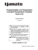
3. Names and functions of parts
Lower stage bath Operation panel
No Name Operation/action
① Start/Stop key The key is used to start/stop operation.
② Up/Down keys These keys are used to select a setting.
③ Enter key This key is used to determine the selected setting.
④ Fixed-value operation key This key is used to select the fixed-value operation.
⑤ Timer operation key Timer operation select key.
This key can be used to select the quick auto stop operation,
the auto stop operation, or the auto start operation.
⑥ Program key Program operation select key.
You can set programs of 6 patterns of 3 types.
⑦ Sub menu key The key is used to set for the overheat preventive device
temperature, calibration offset temperature, key locks, and
the program repeat function.
⑧ Heater lamp The lamp comes on while power is supplied to the heater.
⑨ Alarm lamp The buzzer sounds and this lamp comes on when an error
occurs.
⑩ Auto stop lamp This lamp blinks while the quick auto stop timer or the auto
stop timer is being set and stays on while either timer is
being used.
⑪ Auto start lamp This lamp blinks while the auto start timer is being set and
stays on while it is being used.
⑫ Fixed value operation lamp This lamp blinks while the fixed value operation is being set
and stays on while it is in operation.
⑬ Program operation lamp This lamp blinks while the program operation is being set
and stays on while it is being used.
⑭ Measured temperature
display
Displays the measured temperature in the bath, set
characters, and alarm information.
⑮ Set temperature display Displays the set temperature, set temperature, and timer
remaining time.
⑯ Overheat preventive device
set temperature display
Displays the set temperature of the overheat preventive
device.
⑰ Freezer operation lamp This lamp comes on while power is supplied to the freezer.
⑰⑭
②
③
⑬
⑫
⑪
⑩
⑨
⑧
⑦⑥⑤④
⑮
⑯
①
℃
HEATER
A
LARM
A
UTO STOP
A
UTO START
FIXED TEMP.
PROGRAM
ENTER
FIXED
TEMP
TIMER PROGRAM SUB MENU
START
STOP
・・・・・

13
3. Names and functions of parts
Lower stage bath operation panel
No Name Operation/action
① Manual defrost key Defrost operation is made for five minutes when this key is
pressed.
② Manual defrost lamp This lamp stays on during manual defrost operation.
③ Cycle defrost key When you press this key, cycle of defrost operation ON of
about five minutes and OFF for about 23hours 55 minutes
will be repeated.
Press this key again to stop this function.
④ Cycle defrost lamp During cycle defrost operation, this lamp stays on while
defrost is ON and goes off while defrost is OFF.
MANUAL
DEFROST
ON
ON
OFF
④
①③
CYCLE
DEFROST
LOWER
②

14
3. Names and functions of parts
Lower stage bath Description of characters
Characters used in the model VS4 controller are described below.
Characters Identifier Name Applications
Fix
Fixed value
operation setting
mode
You can select the fixed value operation starting
function.
Sv
Temperature
setting
This is used to set a temperature.
Astp
Timer setting
mode display
This means the quick auto stop operation and the
auto stop operation setting.
Astr
Timer setting
mode display
This means the auto start operation setting.
Tim
Time setting This is used to set a time.
PrG3
Program type
select
This is used select one of program types 1 to 3.
PAt
Program pattern
select
This is used to select a program pattern.
End Step end
This indicates the total number of steps used. See
“Lower stage bath Operating procedures (making
a program)” on P.27.
Sv-1
Program
temperature
setting
This is used to set a temperature of each program
step. See “Lower stage bath Operating
procedures (making a program)” on P.27.
t-1
Program time
setting
This is used to set a time of each program step.
See “Lower stage bath Operating procedures
(making a program)” on P.27.
PS-3
Program repeat
return destination
select
This is used to select a return destination step
during the program repeat operation. See “Using
the program repeat function” on P.32.
Pc-2
Program repeat
number setting
This is used to set a number of program repeat
operations. See “Lower stage bath Operating
procedures (making a program)” on P.32.
cAL
Calibration offset
setting
This is used to input a calibration offset
temperature. See “Lower stage bath Useful
functions (calibration offset function)” on P.35.
oH
Overheat
preventive device
temperature
setting
This is used to set a temperature for the overheat
preventive device. See “Lower stage bath Setting
for the overheat preventive device” on P.20.
Lock
Setting key lock
This locks keys to prevent alteration of setting
information. See “Lower stage bath Useful
functions (lock function)” on P.36.
nG
Setting change
disabled
During operation, you cannot change any inputs
other than temperature and time settings for the
timer and program modes. If you attempt to
change them, nG will appear.
※For operation modes and function characters, see “Lower stage bath Operation modes, function
setting keys and characters” on P.19.

15
3. Names and functions of parts
Upper stage bath Operation panel
No Name Operation/action
①
Start/Stop key The key is used to start/stop operation.
②
Up/Down keys These keys are used to select a setting.
③
Sub menu key The key is used to set for the overheat preventive device
temperature, calibration offset temperature, and key locks.
④ Enter key This key is used to determine the selected setting.
⑤ Fixed value operation key This key is used to select the fixed value operation.
⑥
Timer operation key Timer operation select key.
This key can be used to select the quick auto stop operation,
the auto stop operation, or the auto start operation.
⑦ Heater lamp This lamp stays on while power is supplied to the heater.
⑧
Alarm lamp The buzzer sounds and this lamp comes on when an error
occurs.
⑨
Auto stop lamp This lamp blinks while the quick auto stop timer or the auto
stop timer is being set and stays on during operation.
⑩
Auto start lamp This lamp blinks while the auto start timer is being set and
stays on during operation.
⑪
Fixed value operation lamp This lamp blinks while the fixed value operation is being set
and stays on while it is in operation.
⑫
Measured temperature
display
Displays the measured temperature in the bath, set characters,
and alarm information.
⑬
Set temperature display Displays the set temperature, set temperature, and timer
remaining time.
⑭ Overheat prevention
setting temperature screen
This indicates a set temperature of the overheat preventive
device.
③⑥⑤
②
④
⑪
⑩
⑨
⑧
⑦
⑬
⑭
①
⑫
℃
HEATER
A
LARM
A
UTO STOP
A
UTO START
FIXED TEMP.
ENTER
FIXED
TEMP
TIMER SUB MENU
START
STOP
・・・・・
/