Page is loading ...

Low Constant Temperature Water Bath
Model
BQ100/200/300
Instruction Manual
- Second Edition -
Yamato Scientific Co. LTD.,
This paper has been printed on recycled paper.
z Thank you for purchasing " Low Constant
Temperature Water Bath, BQ Series" of
Yamato Scientific Co., Ltd.
z To use this unit properly, read this "Instruction
Manual" thoroughly before using this unit.
Keep this instruction manual around this unit
for referring at anytime.
WARNING!:
Carefully read and thoroughly understand the
important warning items described in this
manual before using this unit.

Contents
Cautions in Using with Safety................................................................1
•
Explanation.................................................................................................................... 1
•
Table of Illustrated Symbols .......................................................................................... 2
•
Fundamental Matters of “WARNING!” and “CAUTION!” ............................................... 3
Before Using this unit.............................................................................4
•
Requirements for Installation......................................................................................... 4
Description and Function of Each Part.................................................7
•
Main Unit .......................................................................................................................7
•
Control Panel................................................................................................................. 8
•
Characters of Thermo Controller................................................................................... 9
Operation Method .................................................................................10
•
Preparation.................................................................................................................. 10
•
Operation Mode and Function List .............................................................................. 11
•
Operation Mode, Function Setting Key, and Characters ............................................. 13
•
Setting of Overheating Prevention Device .................................................................. 14
•
Fixed Temperature Operation...................................................................................... 15
•
Quick Auto Stop Operation .......................................................................................... 16
•
Auto Stop Operation.................................................................................................... 17
•
Auto Start Operation.................................................................................................... 19
•
Other Functions........................................................................................................... 21
Handling Precautions ...........................................................................22
Maintenance Method.............................................................................24
•
Daily Inspection and Maintenance .............................................................................. 24
Long storage and disposal...................................................................25
•
When not using this unit for long term / When disposing ............................................ 25
In the Event of Failure….......................................................................26
•
Error Display................................................................................................................ 26
After Service and Warranty ..................................................................28
Specification..........................................................................................29
Wiring Diagram......................................................................................31
Replacement Parts Table......................................................................32
Reference...............................................................................................33
•
List of Dangerous Substances .................................................................................... 33

1
Cautions in Using with Safety
Explanation
MEANING OF ILLUSTRATED SYMBOLS
Various symbols are used in this safety manual in order to use the unit without
danger of injury and damage of the unit. A list of problems caused by ignoring
the warnings and improper handling is divided as shown below.Be sure that you
understand the warnings and cautions in this manual before operating the unit.
WARNING!
If the warning is ignored, there is the danger of a problem that
may cause a serious accident or even fatality.
CAUTION!
If the caution is ignored, there is the danger of a problem that may
cause injury/damage to property or the unit itself.
Meaning of Symbols
This symbol indicates items that urge the warning (including the caution).
A detailed warning message is shown adjacent to the symbol.
This symbol indicates items that are strictly prohibited.
A detailed message is shown adjacent to the symbol with specific actions not to
perform.
This symbol indicates items that should be always performed.
A detailed message with instructions is shown adjacent to the symbol.
Illustrated Symbols

2
Cautions in Using with Safety
Table of Illustrated Symbols
Warning
Warning,
generally
Warning,
high voltage
Warning,
high temperature
Warning,
drive train
Warning,
explosive
Caution
Caution,
generally
Caution,
electrical shock
Caution,
scald
Caution,
no road heating
Caution,
not to drench
Caution,
water only
Caution,
deadly poison
Prohibit
Prohibit,
generally
Prohibit,
inflammable
Prohibit,
to disassemble
Prohibit,
to touch
Compulsion
Compulsion,
generally
Compulsion,
connect to the
grounding
terminal
Compulsion,
install on a flat
surface
Compulsion,
disconnect the
power plug
Compulsion,
periodical
inspection

3
Cautions in Using with Safety
Fundamental Matters of “WARNING!” and “CAUTION!”
WARNING!
Do not use this unit in an area where there is flammable or explosive gas
Never use this unit in an area where there is flammable or explosive gas.
This unit is not explosion-proof. An arc may be generated when the power switch is turned on or off,
and fire/explosion may result. (Refer to page33 “List of Dangerous Substances”.)
Always ground this unit
Always ground this unit on the power equipment side in order to avoid electrical shock due to a power
surge.
If a problem occurs
If smoke or strange odor should come out of this unit for some reason, turn off the power key right
away, and then turn off the circuit breaker and the main power. Immediately contact a service
technician for inspection. If this procedure is not followed, fire or electrical shock may result. Never
perform repair work yourself, since it is dangerous and not recommended.
Do not use the power cord if it is bundled or tangled
Do not use the power cord if it is bundled or tangled. If it is used in this manner, it can overheat and
fire may be caused.
Do not process, bend, wring, or stretch the power cord forcibly
Do not process, bend, wring, or stretch the power cord forcibly. Fire or electrical shock may result.
Substances that can not be used
Never use explosive substances, flammable substances and substances that include explosive or
flammable ingredients in this unit. Explosion or fire may occur.
Do not disassemble or modify this unit
Do not disassemble or modify this unit. Fire or electrical shock or failure may be caused.
Do not touch high-temperature parts
The inside of the body or the door may become hot during and just after operation. It may cause burns.
CAUTION!
During a thunder storm
During a thunderstorm, turn off the power key immediately, then turn off the circuit breaker and the main
power. If this procedure is not followed, fire or electrical shock may be caused.

4
Before Using this unit
Requirements for Installation
WARNING!
1. Always ground this unit
• Connect the power plug to a receptacle with grounding connectors.
• Do not forget to ground this unit, to protect you and the unit from electrical shock in case of
power surge. Choose a receptacle with grounding connectors as often as possible.
• Do not connect the grounding wire to a gas pipe, or by means of a lightning rod or telephone
line. A fire or electrical shock will occur.
• Though BQ300 model is the 100V single phase model, this model has the large electric
capacity (over 15A). Be sure to prepare the power switchboard with the specific grand earth
or specific receptacle which has electric capacity over 20A.
2. Choose a proper place for installation
• Do not install this unit in a place where:
♦ Rough or dirty surface.
♦ Flammable gas or corrosive gas is generated.
♦ Ambient temperature exceeds 35°C.
♦ Ambient temperature fluctuates violently.
♦ There is direct sunlight.
♦ There is excessive humidity and dust.
♦ There is a constant vibration.
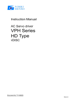
• Install this unit on a stable place with the space as shown below. This unit should be installed
horizontally by using adjusters on the four corners.
Main Unit
More than
30cm
More than
30cm
More than 30cm
Front side

5
Before Using this unit
Requirements for Installation
3. Do not use this unit in an area where there is flammable or explosive gas
• Never use this unit in an area where there is flammable or explosive gas. This unit is not
explosion-proof. An arc may be generated when the power switch is turned ON or OFF, and
fire/explosion may result. (To know about flammable or explosive gas, refer to page33 “List of
Dangerous Substances”.)
4. Do not modify
• Modification of this unit is strictly prohibited. This could cause a failure.
5. Installation on horizontal surface
• Set this unit to the flattest place. Setting this unit to sloping or uneven place could cause the
vibration or noise, or cause the unexpectible trouble or malfunction.

6
Before Using this unit
Requirements for Installation
CAUTION!
6. Choose a correct power distribution board or receptacle
• Choose a correct power distribution board or receptacle that meets the unit’s rated electric
capacity.
Electric capacity: BQ100: AC100 V, 10A
BQ200: AC100 V, 14A
BQ300: AC100 V, 18A
NOTE)
There could be the case that the unit does not run even after turning ON the power. Inspect
whether the voltage of the main power is lowered than the specified value, or whether other
device(s) uses the same power line of this unit. If the phenomena might be found, change the
power line of this unit to the other power line.
7. Before/after installing
• It may cause injure to a person if this unit falls down or moves by the earthquake and the
impact. etc..To prevent, take measures that the unit cannot fall down, and not install to busy
place.
8. Handling of power code
• Do not entangle the power cord. This will cause overheating and possibly a fire.
• Do not bend or twist the power cord, or apply excessive tension to it. This may cause a fire
and electrical shock.
• Do not lay the power cord under a desk or chair, and do not allow it to be pinched in order to
prevent it from being damaged and to avoid a fire or electrical shock.
• Keep the power cord away from any heating equipment such as a room heater. The cord's
insulation may melt and cause a fire or electrical shock.
• If the power cord becomes damaged (wiring exposed, breakage, etc.), immediately turn off the
power at the rear of this unit and shut off the main supply power. Then contact your nearest
dealer for replacement of the power cord. Leaving it may cause a fire or electrical shock.
• Connect the power plug to the outlet which is supplied appropriate power and voltage.

7
Description and Function of Each Part
Main Unit
Front view
Rear view
Clamp Mounting Hole
(The optional clamp set
is to be mounted.)
Top cover
Production plate
Rack (Optional)
Control panel
Power switch
(Earth leakage breaker)
Power cord
Power cord (BQ300)
Specification plate

8
Description and Function of Each Part
Control Panel
① START/STOP Key:
Starts/stops the operation.
② ▲▼ Key:
Uses for rising UP/lowering DOWN the setting value.
③ ENTER Key:
Settles the inputted value.
④ FIXED TEMP Key:
Chooses the fixed temperature operation.
⑤ TIMER Key:
Chooses the timer operation (Quick Auto Stop/Auto Stop/Auto
Start).
⑥ SUBMENU Key:
Uses for setting the overheating prevention temperature,
calibration offset temperature, and key lock function.
⑦ HEATER Lamp:
Lights while the heater works.
⑧ ALARM Lamp:
Lights up when an error occurs. (Buzzer sounds simultaneously.)
⑨ AUTO STOP Lamp:
Blinks while setting quick auto stop timer or auto stop timer.
Lights while quick auto stop timer or auto stop timer is running.
⑩ AUTO START Lamp:
Blinks while setting auto start timer.
Lights while auto start timer is running.
⑪ FIXED TEMP Lamp:
Blinks while setting fixed temperature operation.
Lights while fixed temperature operation is running.
⑫
Measurement Temperature
Display:
Displays the measured temperature, setting character, alarm
information.
⑬
Setting Temperature
Display:
Displays the setting temperature, setting value for timer mode,
remaining time.
⑭
Overheating Prevention
Temperature Display:
Displays the setting temperature for overheating prevention
device.
⑮
Power Switch
(Earth leakage breaker)
Turns ON/OFF the power.
⑯
Electric Leak Test Button Uses for testing breaker condition.
(Refer to Page 24 “Maintenance Method”.)
⑰
Refrigerator Lamp:
Displays the refrigerator status.
The refrigerator is not at work: Lights off
The refrigerator is at work: Lights up
⑦
⑧
⑨
⑩
⑪
③
②
④
⑤
⑥
①
⑭
⑬
⑫
⑮
⑯
⑰

9
Description and Function of Each Part
Characters of Thermo Controller
Character Identifier Name Purpose
FiX
Fixed Temperature
Setting Mode
Used for starting the fixed temperature
operation.
Sv
Temperature Setting
Used for setting the temperature.
AStP
Timer Setting Mode
Display
Represents the setting of quick auto stop or
auto stop operation.
AStr
Timer Setting Mode
Display
Represents the setting of auto start operation.
tim
Time Setting
Used for setting the time.
End
Time Up
Displays when the timer operation is
completed.
cAL
Calibration Offset
Setting
Used for inputting the calibration offset
temperature. (Refer to Page 21 "Use
calibration offset function".)
oH
Overheating Prevention
Setting
Used for setting temperature for overheating
prevention device. (Refer to Page 14 "Setting
of Overheating Prevention Device ".)
LocK
Key Lock
Locks the keys on control panel to protect from
unnecessary operation. (Refer to Page 21
"Use lock function".)
* Also refer to Page 13 "Operation Mode, Function Setting Key, and Characters".

10
Operation Method
Preparation
Water to be Applied
If this unit is operated in the environment with its temperature 5℃ or under, apply the aqueous
[water] solution including 10% ethanol.
If applying water in such an environment, the water might be frozen with the device temperature
set at 0℃, and cause the malfunction. Never freeze the water.
Apply the aqueous [water] solution including ethyl alcohol according to the following table.
Never apply the fluid such as antifreeze solution for automobile or ethylenrglycol to this unit.
Ethanol Density Freezing Point
Wt % Vo1 %
(℃)
4.8 6.0 -2.0
11.3 14.0 -5.0
NOTE)
The alcohol is the volatile liquid. When using the alcohol, refill the alcohol as required every
operation, or replace to new one.
Keep the Appropriate Water Level
Keep the water level 5cm (guideline value) under the top cover of the water bath as the appropriate
water level of this unit.
Cooling Capacity
The time requiring for cooling the 20℃ water temperature down to 0℃ is around 3 hours. However
this time differs depending on the outside temperature.
Cooling Device Performance
This unit is applied the peltier element for the cooling device.
The cooling device turns ON at 40℃ or less and turns OFF over 40℃ automatically.
While the cooling device activates, the LED on the top left of the measurement temperature
display window is lit.
NOTE)
If the temperature of the device is set under 40℃ after operating
with it temperature over 40℃, the cooling device does not activate
until the temperature of the water bath be cooled down till 40℃.

11
Operation Method
Operation Mode and Function List
All the operation mode of this unit is as follows;
No. Name Description Page
1.
Fixed Temperature
Operation
Pressing the FIXED TEMP key enters into the fixed
temperature operation setting mode.
Pressing it again enters into the temperature setting mode.
The "▲▼" are used to set temperature.
Pressing the START/STOP key starts or stops operation.
15
2.
Quick Auto Stop
Operation
This operation is used to specify the period up to automatic
stop during operation.
The period up to operation stop can be set by pressing the
TIMER key during fixed temperature operation.
The "▲▼" are used to set the time.
Pressing the START key starts the quick auto stop operation,
activates the timer function and stops the operation
automatically after specified period.
16
3. Auto Stop Operation
This operation is used to specify the automatic stop time in the
fixed temperature operation.
Pressing the TIMER key displays "AStp".
The setting temperature "SV" can be set by pressing the
ENTER key.
The operation time "tim" can be set by pressing it again.
Pressing the START/STOP key starts the auto stop operation.
17
4. Auto Start Operation
This operation is used to specify the period up to automatic
start after power on.
Pressing the TIMER key displays "AStr".
The setting temperature "SV" can be set by pressing the
ENTER key.
The operation time "tim" can be set by pressing it again.
Pressing the START/STOP key starts the auto start operation.
19
NOTE) This unit is impossible to be changed the mode during the operation. If the mode requires to be
changed, stop the operation.

12
Operation Method
Operation Mode and Function List
The operation function of this unit is as follows;
No. Name Description Page
Auto overheating
prevention function
This function is set to be automatically activated
(auto reset) when the temperature exceeds the
setting temperature by 6℃.
1.
Overheating
prevention
function
Overheating
prevention device
Though the device shares power source, display,
and key input with the controller, it has independent
temperature measurement circuit, CPU, sensor and
output circuit. Overheating prevention temperature
can be set using the operation panel.
The unit stops operation when the device is
activated. The unit starts operation again when the
POWER switch is pressed again (manual reset).
14
2. Calibration offset function
This calibration offset function is for calibrating the
difference occurred between the required in- furnace
temperature and control temperature (sensor
temperature) of the controller. This unit can be
calibrated toward either plus side or minus side of
the whole temperature range.
21
3.
Overheating prevention
temperature calibration
function
The temperature of overheating prevention device is
automatically corrected when the temperature of
controller is collected.
-
4. Recovery at power failure
The unit starts operation with the same condition as
j
ust before power failure if it occurs during operation.
Press the START/STOP key to start the unit again.
-
5. Setting value locking
This function locks the established operation status.
It can be set and cancelled with the SUBMENU key.
21

13
Operation Method
Operation Mode, Function Setting Key, and Characters
The operation mode setting and function setting use the key operation and characters show in the
following figure.

14
Operation Method
Setting of Overheating Prevention Device
The unit has the overheating prevention device (manual reset) that consists of independent temperature
measurement circuit, CPU, sensor and output circuit (it shares power source, display, and key input with
the controller) in addition to the automatic overheating prevention function (auto reset) in the controller.
Setting range/function
The unit has failsafe functions against overheating. One of them is built in the controller and previously
set at factory shipment so to be automatically activated when the temperature exceeds the setting
temperature of temperature controller by 6℃, where the heater repeats on and off.
The other is united with the controller, which can be set by operating the keys on the controller.
The setting range of latter is from 0℃ to 130℃.
In case the temperature in furnace exceeds the setting temperature of controller to reach to that of
overheating prevention device, the circuit is shut off and "Er19" is displayed with blinking on the screen of
controller with buzzer sound.
If the device is once activated,"Er19"continues to be displayed until the power is newly turned on.
Temperature setting procedure
1. Turn on the power (turn on the breaker in front)
• The default value is displayed for about four seconds after
turning on the power. The screen then displays the initial
setting. The current temperature in furnace, operation
mode character and setting temperature of overheating
prevention device are displayed on respective screens.
2. Set the temperature for overheating prevention
① Press the SUBMENU key.
② Press the " ▼▲" several times to select the setting
character of overheating prevention temperature "OH".
③ Press the ENTER key. The current setting temperature is
displayed with blinking on the setting temperature screen.
Note: To prevent improper operation, set the value 10℃ or more
over the setting temperature of controller.
④ Select the value using the " ▼▲"and then press the
ENTER key. This completes the setting.
Notes:
• The standard setting temperature of device is "the maximum setting temperature of unit plus
10℃" or "setting temperature plus 10℃". If the unit performs improper operation, increase it
5℃ more.
• The setting range of overheating prevention device is from 0℃ to 130℃. Improper setting of
temperature may cause inoperative of unit, malfunction of device, e.g. it is activated during
increasing in temperature in furnace, or unexpected accidents such as fire disaster. To
prevent such matters, set a proper value. The temperature is set at 90℃ beyond these
setting values. In this case, follow the instruction ③ of Section 2 above.
• In some case, the overheating prevention device is possible to be activated by mistake when
its yield temperature is set to around room temperature.
• The purpose of overheating prevention device is to protect the unit from overheating. It does
not intend to protect the samples, or to protect them from the accident caused by the use of
explosive or inflammability.

15
Operation Method
Fixed Temperature Operation
Fixed temperature
operation procedure
1. Turn on the power (turn on the breaker in front)
The default value is displayed for about four seconds after turning
on the power. The screen then displays the initial setting. The
current temperature in furnace, operation mode character and
setting temperature of overheating prevention device are displayed
on respective screens.
2. Select the operation mode
• Press the FIXED TEMP key to display "FIX", which indicates the
fixed temperature operation, on the center display screen.
3. Set the temperature
• Press the FIXED TEMP key again.
• The setting temperature screen displays the character "SV"
which indicates the temperature setting. Also it displays the
current setting temperature with blinking. The FIXED TEMP
lamp blinks, too.
• Set the temperature by pressing the "▼▲".
4. Start operation
• Press the orange START/STOP key for about one second. The
unit starts operation and the blinking FIXED TEMP lamp lights
on.
5. Stop operation
• Press the orange START/STOP key for about one second. The
unit stops operation and the FIXED TEMP lamp lights off. The
screen returns to the initial setting screen.
To correct or check setting…
Press the FIXED TEMP key again to correct or check the setting.
Changing the setting temperature during operation is also possible by pressing the FIXED TEMP key.
Measurement temperature screen:
Displays the current temperature in furnace.
Setting temperature screen:
Displays the operation mode character. (Refer to Page 13)
Overheating prevention screen:
Displays the setting temperature of overheating prevention device

16
Operation Method
Quick Auto Stop Operation
Quick auto stop
operation procedure
This operation is used to specify the period up to automatic stop,
i.e., sets the auto stop timer during operation.
1. Set the time up to stop during fixed temperature operation
• Check that the FIXED TEMP lamp lights on and that the unit is
under operation.
• Press the TIMER key.
• The measurement temperature display screen displays the
character "tim", which indicates the timer setting. The setting
temperature display screen displays the current setting time with
blinking.
• Select the time by pressing the "▼▲".
Timer function:
• The maximum setting time is "999 hours and 50 minutes".
• The time can be set in increments of a minute under 99 hours
and 59 minutes.
• It can be set in increment of ten minutes over 100 hours.
• The "▼▲"can change the setting time quickly when it is pressed
continuously. Press them discontinuously when fine adjustment
is needed.
2. Start timer operation
• Press the START/STOP key for one second after deciding the
time.
• Timer operation starts with the FIXED TEMP and AUTO STOP
lamps lighting on.
• The timer is activated at the point when the START/STOP key is
pressed.
3. Stop/terminate timer operation
• The operation stops automatically at setting time.
• Buzzer continues to sound for about five minutes at operation
stop.
• The setting temperature screen displays the character "End",
which indicates termination of operation, with the FIXED TEMP
and AUTO STOP lamps lighting on. Press the START/STOP
key to terminate the timer operation mode. The screen returns
to the initial setting screen.
To correct or check setting…
Changing the setting temperature during operation is possible by pressing the FIXED TEMP key. Press
the ENTER key after changing the setting.
Changing the setting temperature during operation is available by pressing the FIXED TEMP key. Press
the ENTER key after changing the setting.
Press the ▼ key to display the setting temperature, operation mode and residual time on the setting
temperature screen.

17
Operation Method
Auto Stop Operation
Auto stop operation
procedure
This operation is used to specify the automatic stop time in the
fixed temperature operation.
1. Set stop time
① Press the TIMER key on the initial screen.
Press the TIMER key again. The setting temperature display
screen displays the character "AstP", which indicates the auto
stop operation, with blinking.
② Press the ENTER key.
The measurement temperature screen displays the character
"SV", which indicates the temperature setting. The setting
temperature screen displays the current setting temperature with
blinking. The AUTO STOP lamp blinks, too.
③ Set the temperature using the "▼▲".
④ Press the ENTER key again.
The measurement temperature display screen displays the
character "tim", which indicates the timer setting. The setting
temperature display screen displays the current setting time with
blinking.
⑤ Set the time using the "▼▲".
Timer function:
• The maximum setting time is "999 hours and 50 minutes".
• The time can be set in increments of a minute under 99 hours
and 59 minutes.
• It can be set in increment of ten minutes over 100 hours.
• The "▼▲"can change the setting time quickly when it is pressed
continuously. Press them discontinuously when fine adjustment
is needed.
2. Start timer operation
• Press the START/STOP key for one second after deciding the
time.
• Timer operation starts with the AUTO STOP lamp lighting on.
• The timer is activated at the point when the temperature in
furnace (measurement temperature) reaches to the setting
temperature.

18
Operation Method
Auto Stop Operation
3. Stop/terminate timer operation
• The operation stops automatically at setting time.
• Buzzer continues to sound for about five minutes at operation
stop.
• The setting temperature screen displays the character "End",
which indicates termination of operation, with the FIXED TEMP
and AUTO STOP lamps lighting on. Press the START/STOP
key to terminate the timer operation mode. The screen returns
to the initial setting screen.
To correct or check setting…
Changing the setting temperature or time during operation is possible by pressing the TIMER key. Use
the "▼▲" to change the setting value. Press the ENTER key respectively after changing the setting.
Press the "▼" to display the setting temperature, operation mode and residual time on the setting
temperature screen.
/