Page is loading ...

Rapid Heating / Cooling Oven
Model:DKG610(V)/650(V)
Model:DKG810(V)/850(V)
Instruction Manual
Second Version
● Thank you very much for purchasing this Yamato
DKG Series.
● Please read the “Operating Instructions” and
“Warranty” before operating this unit to assure proper
operation. After reading these documents, be sure to
store them securely together with the “Warranty” at a
handy place for future reference.
Warning:
Before operating the unit, be sure to read
carefully and fully understand important
warnings in the operating instructions.
Yamato Scientific Co., Ltd.
This paper has been printed on recycled paper.


Contents
1. Safety precautions.................................................................. 1
Explanation of pictograms ............................................................. 1
List of symbols ....................................................................... 2
Warning・Cautions ................................................................... 3
2. Before operating the unit ............................................................ 4
Precautions when installing the unit ..................................................... 4
Installation procedures/precautions...................................................... 9
3. Names and Functions of Parts ...................................................... 10
Main unit ........................................................................... 10
Structural diagram ................................................................... 12
Operation panel ..................................................................... 13
Description of characters ............................................................. 14
4. Operating Procedures.............................................................. 16
List of operation modes and functional menus ........................................... 16
Operation mode and function setting keys and characters ................................. 18
Setting of the overheat preventive device ............................................... 19
Operation steps(Fixed temp operation) ............................................... 20
Operation steps(Quick Auto Stop operation)........................................... 21
Operation steps(Auto Stop operation) ................................................ 22
Operational steps(Auto Start operation) .............................................. 24
Creating a program .................................................................. 26
Program repeat operation............................................................. 31
Program sheet ...................................................................... 32
Useful functions(calibration offset function)............................................ 34
Useful function(Lock function)....................................................... 35
Useful function(
External alarm output) ............................................... 36
Useful functions (Output terminal) ...................................................... 37
Option (Overheat preventive unit) ...................................................... 39
Option (RS485 communication function) ................................................ 40
5. Handling Precautions .............................................................. 52
6. Maintenance procedures ........................................................... 54
Daily inspection/maintenance.......................................................... 54
7. When the unit is not to be used for a long time or when disposing...................... 55
When the unit is not to be used for a long time or when disposing........................... 55
Notes about disposition............................................................... 55
8. Troubleshooting................................................................... 56
Safety device and error codes ......................................................... 56
When a malfunction is suspected ...................................................... 57
9. After sales service and warranty .................................................... 58
When requesting a repair ............................................................. 58
10. Specifications.................................................................... 59
11. Wiring diagram ................................................................... 61
12. Replacement parts list ............................................................ 63
13. List of dangerous materials........................................................ 65
14. Standard installation manual....................................................... 66

1
1. Safety precautions
Explanation of pictograms
About pictograms
A
variety of pictograms are indicated in this operating instruction and on
products for safe operation. Possible results from improper operation
ignoring them are as follows.
Be sure to fully understand the descriptions below before proceeding to the
text.
Warning
Caution
Indicates a situation which may result in minor injury (Note 2) and
property damages (Note 3.)
(
Note 1
)
Serious injury means a wound, an electrical shock, a bone fracture or intoxication that ma
y
leave after effects or require hospitalization or outpatient visits for a long time.
(
Note 2
)
Minor injury means a wound or an electrical shock that does not require hospitalization o
r
outpatient visits for a long time.
(
Note 3
)
Property damage means damage to facilities, devices and buildings or other properties.
Meanings of pictograms
This pictogram indicates a matter that encourages the user to adhere to warning
(“caution” included).
Specific description of warning is indicated near this pictogram.
This pictogram indicates prohibitions
Specific prohibition is indicated near this pictogram.
This pictogram indicates matters that the user must perform
Specific instruction is indicated near this pictogram.
Indicates a situation which may result in death or serious injury (Note 1.)

2
1. Safety precautions
List of symbols
Warning
General warnings
Danger!: High
voltage
Danger!: High
temperature
Danger!: Moving
part
Danger!: Hazard
of explosion
Caution
General cautions Electrical shock! Burning!
Caution for no
liquid heating!
Caution for water
leak!
For water only
Poisonous
material
Prohibitions
General bans Fire ban
Do not
disassemble
Do not touch
Compulsions
General
compulsions
Connect ground
wire
Install levelly
Pull out the power
plug
Regular
inspection

3
1. Safety precautions
Warning・Cautions
Warning
Never operate the unit in an atmosphere containing flammable or explosive gas
Never operate the unit in an atmosphere containing flammable or explosive gas.
Otherwise, an explosion or a fire may result since the unit is not explosion-proof.
See section “13. List of dangerous materials” on page65.
Be sure to connect the ground wire.
Be sure to connect the ground wire correctly. Otherwise, electrical leak may result and cause an
electrical shock or a fire.
Ban on operation when an abnormality occurs
When a smoke or an unusual odor is seen or sensed, immediately turn the ELB on the main unit
off and pull out the power plug. A fire or an electrical shock may result.
Never use electrical power cords bundled.
When these are used bundled, they might overheat causing a fire.
Take care not to damage electrical power cords.
Avoid tightly bend, pull with a strong force or twist to prevent electrical power cords from
damaging. A fire or an electrical shock may result.
Never use an explosive or a flammable material with this unit.
Never use an explosive material, a flammable material or a material containing them. An
explosion or an electrical shock may result.
See section “13. List of dangerous materials” on page 65.
Never try to touch a hot part.
Some parts of the unit are hot during and immediately after operation. Take special care for
possible burning.
Never try to disassemble or alter the unit.
Never try to disassemble or alter the unit. A malfunction, a fire or an electrical shock may result.
Caution
When a thunder is heard.
When a thunder is heard, turn the main power off immediately. A malfunction, fire or an electrical
shock may result.

4
2. Before operating the unit
Precautions when installing the unit
1. Carefully select an installation site.
Take special care not to install the unit at a place described below:
・ Uneven surfaces or dirty surfaces
・ Where flammable gas or corrosive gas exists
・ Where the ambient temperature is 35℃ or more
・ Where temperature changes severely
・ Where dusty and humidity is high
・ Where subject to direct sunlight
・ Where vibration is severe
Install this unit at a place with spaces shown below.
2. Install the unit on a level surface.
Install the unit on a level surface. If the whole bottom surface of the unit does not contact the
surface evenly, vibrations or noises may result. This might cause unexpected troubles or
malfunctions.
The unit weight: DKG610(V)/650(V): Approx.110 ㎏, DKG810(V)/850(V): Approx.155 ㎏
When lifting the unit for transportation and installation, carefully handle it by at least two
people.
3. Installation
The unit might fall down or move by an earthquake or an impact resulting a personal injury.
We recommend making safety measures such as to avoid installing the unit at a place other
than busy places.
Main
Body
80 ㎝ or more
20 ㎝ or more 20 ㎝ or more
80 ㎝ or more

5
2. Before operating the unit
Precautions when installing the unit
4. Secure sufficient ventilation for the unit.
Do not operate the unit when suction port and heat radiation port on the side and rear panels
are blocked.
Internal temperature of the unit will rise degrading the performance and an accident, a
malfunction or a fire may result.
5. Do not operate the unit at such a place that may subject to splash.
Do not operate the unit at such a place that may subject to splash. Liquid entering the inside
may cause an accident, a malfunction, an electrical shock or a fire.
6. Never operate the unit in an atmosphere containing flammable or explosive gas.
Never operate the unit in an atmosphere containing flammable or explosive gas. Since the
unit is not explosion-proof, an arc is discharged when switching the ELB “ON(|)” and
“OFF(○)” and during operation and a fire or an explosion may result.
See the section “13. List of dangerous materials” on page 65 for flammable and explosive
gases.
Explosive gases
Flammable gases

6
2. Before operating the unit
Precautions when installing the unit
7. Be sure to connect the power plug to the dedicated power distribution panel or
a wall outlet.
Use a power distribution panel or a wall outlet that meets the electrical capacity of the unit.
Electrical
capacity:
DKG610(V) AC200V-220V 13.3±10%~14.6±10% A
DKG650(V) AC230V-240V 11.6±10%~12.1±10% A
DKG810(V) AC200V-220V 18.5±10%~20.3±10% A
DKG850(V) AC230V-240V 16.2±10%~16.8±10% A
* When the unit will not start even when you turn the Electric Leakage Breaker to “ON(|)”,
check for low main voltage or if the unit is connected to the same power supply line as other
devices and connect it to another line if necessary.
Avoid connecting too many devices using a branching outlet or extending a wire with a cord reel
or heating function and temperature controlling function may degrade due to voltage drop.
Do not connect the unit to any parts or lines other than a correct power supply line such as a
gas pipe, a water pipe or a telephone line.
Otherwise, an accident or a malfunction may result.
8. Handling of a power cord
Never use electrical power cords bundled. When these are used bundled, they might
overheat causing a fire.
Do not convert, forcibly bend, twist or pull the power cord. Otherwise, a fire or an electrical
shock may result.
Do not place the power cord under a desk or a chair, or sand between objects to avoid it
from being damaged.
Otherwise, a fire or an electrical shock may result.
Do not place the power cord close to a stove or other heat generating device. Sheath of the
cord may burn and result in a fire or an electrical shock.
If the power cord should be damaged (exposure of core wire or disconnection), immediately
turn the ELB off (○), turn the power supply off and ask your dealer to replace the cord. If
the unit is operated with a damaged power cord, a fire or an electrical shock may result.
Connect the power cord to an appropriate wall outlet or distribution board.
9. Be sure to connect the ground wire.
・ When the unit has no ground terminal, class D grounding work is necessary and please
consult your dealer or our nearest sales office.
・ Securely connect to an outlet.
The unit does not have a power plug. Connect
the earth correctly to suit the power facility to
be connected.
Do not connect the grounding wire to any parts or lines other than a correct grounding
terminal such as a gas pipe, a water pipe or a telephone line.
Otherwise, an accident or a malfunction may result.
M5 round
terminal
Green
(
to eart
h
terminal
)
Bl
ac
k
(
to rate
d
power
terminal
)
Whi
te
(
to rate
d
power
terminal)

7
2. Before operating the unit
Precautions when installing the unit
10. Be careful for the colors of core wires when connecting the power cords.
Be sure to first make sure that the breaker on the power
facility side is “Off (○)” before connecting the power
cords.
The unit does not have a power plug. Select and connect
a plug and a terminal with correct ratings suited to the
power source capacity of the power facility to be
connected. (See the table in the right)
Core wire
color
Indoor wiring
Black Voltage side
White Earth side
Green Earth
11. .Do not attempt to alter the unit 12. Do not put too many specimens.
The customer shall never attempt to alter
the unit. Otherwise a malfunction may
result.
The withstand load of a shelf board is 15kg
when the load is evenly distributed.
Put specimens dispersed.
When shelf boards have been placed on all
stages, take care not to exceed the total
withstand load.
《Total withstand load》
DKG610(V),DKG650(V):45Kg or less
DKG810(V),DKG850(V):75Kg or less
Specimen
15kg
Shelf board
13. Do not set too many specimens. 14. Do not place an object on the
bottom plate.
Too many specimens will prevent correct
temperature control. In order to assure
temperature precision, be sure to use shelf
boards and put specimens dispersed, and
secure at least 30% of space inside the
bath.
Secure at least 30% of space
Operating the unit with placing the
specimen directly on the bottom plate of the
internal bath will prevent performance of
the product from fully exerting, increase the
internal temperature excessively and may
cause a malfunction.
Never place a specimen on the bottom
plate of the internal bath.
See “15. Installing shelf boards and placing
specimen” on P8.
MODIFICATION

8
2. Before operating the unit
Precautions when installing the unit
15. Placing shelf boards and specimens
Shapes of shelf boards will differ depending on the model and each model contains two or
four boards.
One of them has been fixed on the lowest stage of the shelf peg pillars inside the unit with
screws at the time of factory shipping.
Set the remaining shelf boards to appropriate positions in the unit.
One of the shelf boards has been
fixed on the lowest stage of the shelf
peg pillars inside the unit with screws
at the time of factory shipping.
A heater and a fan are installed under
the rectifier plate. And temperature of
the rectifier plate and around it is
always higher than the set
temperature and if you place a
specimen directly on the plate, it may
burn or a fire may result.
Slit at the front side of the rectifier
plate is the suction slit of the hot air
convection route. Never block this slit
with a specimen or other objects.
For this reason, the shelf boards are
held with screws as shown in the
drawing to prevent specimens from
being placed directly.
If you need to remove shelf boards
due to the shape of a specimen to
set, secure sufficient space to the
rectifier plate and never place the
specimen directly.
16. About handling of the exhaust port (manual damper)
The exhaust port is located at the rear of the main unit. While the manual damper is used, hot
air will be exhaust at the port. So be sure to connect the exhaust duct and assure sufficient
space behind the back of the main unit. The exhaust port and around it will become hot and
take sufficient care for burning.
Exhaust port flange dia.:Φ80mm
Air amount when damper is fully opened(environmental temp.:23℃, at no load, in-bath
temp:25℃)
DKG610(V),DKG650(V):1.5 ㎥/min
DKG810(V),DKG850(V):1.4 ㎥/min
About ventilating operation
When you attempt to increase temperature with the manual damper open, note that the
target temperature may not be reached depending on the openness of the damper, the
environmental temperature, or the amount of specimen.
(Temperature can be raised up to 260℃ at environmental temp:23℃,no-load, and up to
50% of damper openness. Note that the temperature rise time is not guaranteed.)
See ”3.Names and functions of parts” on P10 & 11.
Shelf pilla
r
Rectifying
board
Shelf peg
Screw
Screw
Shelf board
Screw

9
Precautions when Installing the Unit
Installation procedures/precautions
(1)
Release the stopper lock of the caster wheels.
Set the stoppers of the caster wheels to the
high position as shown in the drawing in the
right.
Now the lock is released.
(Only two caster wheels at the front of the
unit have stoppers.)
キャスター
ストッパー
ロック
ロック解除
(2) Transport the unit to the installation site.
* Transporting the unit over a gap may give an excessive shock to the caster wheels and
may damage them.
If such trouble is expected, lift the unit and transport it over the gap.
(3) Lock the caster stoppers when the unit has been transported to the installation site.
They are locked.
(4) Connection of the power supply.
Make sure that the ELB is “OFF(○)” before connecting the power supply to the power
distribution board and the outlet.
※(1),(2),and (3) are for DKG810(V)/DKG850(V) only.
Lock release
Lock
Stopper
Caster

10
3. Names and Functions of Parts
Main unit
DKG610 (V)/650(V)
Exhaust port(Φ80mm)
Cable port
Alarm output terminal (standard)
Optional part port
Temp. Output (4-20mA)
External com (RS485)
Shelf board
ELB
Ope
r
ation panel
Door
Handle
Temperature sensor
access
p
ort
Power cord
Manual damper
operation assembly
Rating nameplate
Serial # name
p
late
Radiation
p
ort
Exhaust damper access
port and optional part (auto
damper) connection port

11
3. Names and Functions of Parts
Main unit
Front of DKG810 (V)/850(V)
Operation panel
Door
Handle
ELB
Cable port
Shelf board
Caster wheels: at 4 points
( Two front wheels have
locks.)
Temperature sensor access
p
ort
Power cord
Alarm output terminal (standard)
Optional part port
Temp. Output (4-20mA)
External com (RS485)
Exhaust port
(
Φ
80
mm
)
Manual damper
operation assembly
Rating nameplate
Serial # nameplate
Radiation port
Exhaust damper access port
and optional part (auto damper)
connection port

12
3.Names and Functions of Parts
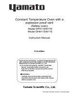
Structural diagram
The air supply port and the exhaust port are linked for the supply/exhaust system of this unit. Four
openness levels are available: 25%, 50%, 75%, and 100%. At full open, or 100% of openness, total
supply/exhaust will be complete external air displacement, which will improve cooling efficiency. When
operation is finished and you want to start cooling operation, first press the STOP button and then
start damper operation. During displacement operation (damper is opened during operation), the
target temperature may not be reached and adjust damper openness according to the specific
conditions.
※Average measured value for 5 points on the exhaust port looked from above.
Inside the bath
Door
Damper control
assembly
Circulation fan motor
Heater
Control sensor
During regular operation (Damper
o
p
enness: 0%)
Exhaust portφ80
Air supply port
Exhaust flow at different damper openness (environmental temp: 23℃, no-load, in-bath temp:25℃)※
0% (full close) 25% 50% 75 100%(full open)
600 type 0.0 ㎥/min 0.1 ㎥/min 0.1 ㎥/min 0.3 ㎥/min 1.5 ㎥/min
800 type 0.0 ㎥/min 0.1 ㎥/min 0.1 ㎥/min 0.5 ㎥/min 1.4 ㎥/min
During exhaust operation (Damper openness: 100%)
Exhaust: From A through internal bath side BOX and exhausted at B
Exhaust port
measurement points: 5

13
3. Names and Functions of Parts
Operation panel
MEASURED TEMP.
℃
HEATER
ENTER
SET
TEMP.
OVER TEMP.
RUN
STOP
SUB
MENU
TIMER
FIXED
TEMP.
PROGRAM
PROTECTOR
ALARM
AUTO STOP
AUTO START
FIXED TEMP.
PROGRAM
No Name Operation/action
① RUN/STOP Key This key is used to start/stop operation.
② ▽,△ Key These keys are used to select a setting.
③ ENTER Key This key is used to determine a setting you selected.
④ FIXED TEMP. Key This key is used to select the fixed temperature operation.
⑤ TIMER Key This key is used to select the timer operation.
You can select from quick auto stop operation, auto stop operation, and
auto start operation.
⑥ PROGRAM Key This key is used to make a program and to select program operation.
You can set a program fro m 3 types, 6 patterns.
⑦ SUB MENU Key This key is used to set overheat preventive device temperature, a
temperature for calibration offset, key lock, and the program repeat
function.
⑧ HEATER Lamp This lamp comes on while power is supplied to the heater.
⑨ ALARM Lamp Buzzer sounds and this lamp come on when an error occurs.
⑩ AUTO STOP Lamp This lamp flashes during quick auto stop timer setting and stays on
during operation.
This lamp flashes during auto stop timer setting and stays on during
operation.
⑪ AUTO START Lamp This lamp flashes during auto start time setting and stays on during
operation.
⑫ FIXED TEMP. Lamp This lamp flashes during fixed temp operation setting and stays on during
operation.
⑬ PROGRAM Lamp This lamp flashes during program operation setting and stays on during
operation.
⑭ MEASURED TEMP.
Display
The display indicates measured in-bath temperature, setting characters,
and alarm information.
⑮ SET TEMP. Display The display indicates a set temperature, timer setting, and timer
remaining time.
⑯ OVER TEMP.
PROTECTOR
Display
The display indicates a set temperature of the overheat preventive
device.
⑭
⑧
⑨
⑩
⑪
⑫
⑬
③
④
②
⑤
⑮
⑯
①
⑦
⑥

14
3. Names and Functions of Parts
Description of characters
Characters used on the controller of this unit are described here.
Characters Identifier Name Application
Fix
Fixed Temp operation
setting
This means Fixed Temp operation
settings.
Sv Temperature setting This is used to set a temperature.
AStP Auto Stop setting
This is used to set Auto Stop
operation.
AStr Auto Start setting
This is used to set Auto Start
operation.
tim Time setting Used for setting a time.
PrG3 Program type selection
This is used to select a program type
to use from 1 to 3.
See “Creating a program” on P.26.
PAt
Program pattern
selection
This is used to select a program
pattern to use.
See “Creating a program” on P.26.
End Time up
This is displayed when Timer
operation is finished.
See P.21 and 23.
Sv-1
Program temperature
setting
This is used to set a temperature for
each step of a program.
(Displayed range is Sv-1~Sv-30)
t-1 Program time setting
This is used to set a time for each
step of a program.
(Displayed range is t-1~t-30)
PS-3
Selection of return
destination of program
repeat
This is used to select a return
destination step for program repeat
operation.
See “Program Repeat operation” on
P. 3 1.
Pc-2
Setting of program
repeat
This is used to set a number of
Program Repeat operation.
See “Program Repeat operation” on
P. 3 1.

15
3.Names and Functions of Parts
Main body
Character Identifier Name Application
cAL Calibration Offset setting
This is used to enter a calibration
offset temperature.
See “Useful functions (Calibration
Offset function)” on P. 34.
oH
Overheat preventive
device temperature
setting
This is used to set a temperature of
the overheat preventive device. See
“Setting the overheat preventive
device” on P.19.
Lock Setting key lock
Key locks settings to prevent their
alterations.
See “Useful functions (Lock function)”
on P.35.
door Door open display
This indication appears when the door
is opened.
If you open the door during operation,
control (heater and fan) will be
stopped, and automatically recovers
when you close the door.
※ For characters of operation modes and function setting keys, see “Operation modes and function
setting keys and characters” on P.18.

16
4. Operating Procedures
List of operation modes and functional menus
Operation modes of this unit are as follows.
№ Name Description Page
1
Fixed Temp
operation
Pressing
FIXED TEMP. key enters the Fixed Temp operation
setting mode.
Pressing
FIXED TEMP. key again enters the Temperature
Setting mode.
Use
▽ and △ keys to set a temperature.
Press RUN/STOP key to start operation and press RUN/STOP
key to stop operation.
P. 2 0
2
Quick Auto Stop
operation
This function is used when, for example, “to stop operation in
the middle of it after several hours”.
You can press
TIMER key to set a time to stop operation
during the Fixed Temp operation.
Use
▽ and △ keys to set a time.
Pressing RUN/STOP key starts Quick Auto Stop operation and
the timer starts in the middle of it and automatically stops
operation when after set time elapsed.
P. 2 1
3 Auto Stop operation
This is used to set “operation to automatically stop when
setting Fixed Temp operation.”
Press
TIMER key to display “AStP”.
You can press ENTER key to set a set temperature “Sv”.
You can set an operation time “tim” by pressing ENTER key
again.
Pressing
RUN/STOP key starts Auto Stop operation.
P. 2 2
4 Auto Start operation
This is used to “automatically start several hours” after turning
power on.
Press
TIMER key to display “AStr”.
You can press ENTER key to set a set temperature “Sv”.
You can set an operation time “tim” by pressing ENTER key
again.
Pressing
RUN/STOP key starts Auto Start operation.
P. 2 4
5 Program operation
This is used to increase or decrease temperature above or
below set temperature and depending on specific time
periods.
Press
PROGRAM key to display “PrGn”.(n:1,2,3)
Press PROGRAM key again to select a program mode you
want.
For “PrG2” and “PrG3”, press
ENTER key to select a
pattern ”Pat” you want.
Press
RUN/STOP key to start program operation.
P. 2 6
※You cannot change the operation mode while the unit is in operation. Be sure to first stop
operation before trying to change the mode.

17
4. Operating Procedures
List of operation modes and functional menus
Operation modes of this unit are as follows.
№ Name Description Page
1
Overheat Preventive
function
Automatic Overheat Preventive function:
The function has been set to automatically activate when
in-bath temperature rises together with the unit set
temperature to a temperature 12℃ plus that temperature
(automatic recovery).
Overheat preventive device:
The power supply unit, the display, and the key input
assembly are common with the controller, while the
device has an independent temperature detecting circuit,
a CPU, sensors, and an output circuit, for which a
temperature you want can be set on the operation panel.
If the overheat preventive device has activated, the unit
will stop and will not recover until the power switch is
turned on again. (Manual recovery).
P. 1 9
2
Calibration Offset
function
The Calibration Offset function compensates any
differences that may occur between the target in-bath
temperature and the temperature on the controller (sensor
temperature).
You can compensate in plus or minus direction over the
entire temperature range of the unit.
P. 3 4
3
Overheat Preventive
Temperature
Compensation function
When you perform temperature compensation for the
controller in item 2 above, temperature to be input to the
overheat preventive device will also be compensated
automatically.
-
4
Power Failure
Compensation function
When a power failure occurred in the middle of operation
and recovered, this function resumes operation at the status
immediately before the failure.
-
5 Setting Lock function
This function is used to lock set operation status.
You can set and cancel lock using the
SUB MENU key.
P. 3 5
/