Page is loading ...


This manual must be read before using the
Airmaster air handling unit. Compliance
with the manual ensures correct use of this
product.
When using the unit in a room with a re or
stove drawing air from the room, all applica-
ble provisions must be observed.
The unit should not be used in rooms with
abrasive particles or ammable or corrosive
gas in the air, in wet rooms or explosion-
protected rooms.
The unit should not be used without the
lters specied in this manual.
The manufacturer cannot be held liable for
damage arising from use in contravention of
these instructions.
The manufacturer reserves the right to make
changes without notice. All values stated
are nominal values and can be aected by
local conditions.
Failure to observe the warnings indicated by
a danger symbol implies a risk of personal
injury or damage to property.
This guide relates to the Airmaster unit it
accompanies plus all equipment, and must
be given to and saved by the unit’s owner.
All necessary data and guides to network
integration can be downloaded from
www.airmaster-as.com .
SAFETY INSTRUCTIONS
WARNINGS
Place of installation and serial numbers (S/N):
Type:
Delivery date:
Place of installation:
S/N of Air handling unit:
S/N of Cooling Module:
The unit must be disconnected from mains
electricity and precautions taken against
accidental use before service covers can be
opened.
The unit may not be started up until all service
covers and grates on duct connections have
been installed.

3
Table of Contents
1. Airlinq® ...........................................................................................................................................................5
2. Function Principle .........................................................................................................................................5
3. Airlinq Viva (White Control Panel) ................................................................................................................6
3.1. Control Elements ............................................................................................................................................................................................6
3.2. Operation ...........................................................................................................................................................................................................6
3.2.1. Automatic Operating Lock .......................................................................................................................................................... 6
3.2.2. Child Lock ...........................................................................................................................................................................................6
3.2.3. Start, Standby and Switch O................................................................................................................................................... 7
3.2.4. Air Flow - Manuel Setting ...........................................................................................................................................................8
3.2.5. Holiday Mode - Activation ...........................................................................................................................................................9
3.3. Warning and Alarm .........................................................................................................................................................................................9
4. Airlinq Orbit (Black Control Panel) ..............................................................................................................11
4.1. Control Elements .......................................................................................................................................................................................... 11
4.2. Operation ......................................................................................................................................................................................................... 11
4.2.1. Automatic Operating Lock ........................................................................................................................................................ 11
4.2.2. Air Flow - Manuel Setting .........................................................................................................................................................12
4.2.3. Automatic Operation ..................................................................................................................................................................13
4.2.4. Operating Menu ............................................................................................................................................................................13
4.2.4.1. Start and Standby ......................................................................................................................................................13
4.2.4.2. O .....................................................................................................................................................................................14
4.2.4.3. Holiday Mode - Activation .......................................................................................................................................14
4.2.4.4. Status ..............................................................................................................................................................................14
4.2.4.5. Setup ...............................................................................................................................................................................17
Timers .............................................................................................................................................................................17
Date and Time ..............................................................................................................................................................19
Default Flow .................................................................................................................................................................19
Default Temp ................................................................................................................................................................ 19
High Temperature ......................................................................................................................................................19
Reset Service ................................................................................................................................................................19
Data Log .........................................................................................................................................................................19
Startup Guide .............................................................................................................................................................. 20
4.2.4.6. Lock Screen .................................................................................................................................................................. 20
4.2.5. CO2 Status ....................................................................................................................................................................................... 20
4.2.6. Airlinq BMS ...................................................................................................................................................................................... 21
4.2.6.1. Select a Group/Unit .................................................................................................................................................. 22
4.2.6.2. Start, Standby and Switch O .............................................................................................................................. 22
4.3. Warning and Alarm ...................................................................................................................................................................................... 23

4
5. Control Functions ....................................................................................................................................... 24
5.1. Timer-Controlled Ventilation .................................................................................................................................................................. 24
5.2. Night Time Cooling ...................................................................................................................................................................................... 24
5.3. Holiday Mode .................................................................................................................................................................................................24
5.4. Start and Stop Using External Contacts.............................................................................................................................................24
5.5. Start and Stop Using a PIR Sensor ....................................................................................................................................................... 24
5.6. Control Using a CO2 Sensor ...................................................................................................................................................................... 25
5.7. Boost ................................................................................................................................................................................................................. 26
5.8. Control Using an Analogue BMS ............................................................................................................................................................ 26
5.9. Cooling Module Operation........................................................................................................................................................................ 26
6. Internal Control Functions ......................................................................................................................... 26
6.1. Low Temperature (“Low Temp”)............................................................................................................................................................ 26
6.2. Preheat ............................................................................................................................................................................................................ 26
6.3. Virtual Preheat ..............................................................................................................................................................................................27
6.4. High Temperature (“High Temp”) ..........................................................................................................................................................27
7. Service and Maintenance ........................................................................................................................... 28
7.1. External Cleaning......................................................................................................................................................................................... 28
7.2. Internal Cleaning ..........................................................................................................................................................................................28
7.3. Cleaning the Condensate System......................................................................................................................................................... 28
7.4. Filter Change ................................................................................................................................................................................................. 29
7.4.1. Reset Service ................................................................................................................................................................................ 29
7.4.2. Cooling Module Filter Change ................................................................................................................................................ 29
7.4.3. Filter Change for CV 80-200, DV 1000, AM 100, 300, 500, 800, 1000 .............................................................. 30
7.4.4. Filter Change AM 900 and AM 1200 ....................................................................................................................................31
7.5. Filter List ......................................................................................................................................................................................................... 33
7.6. Setting Inlet Opening ................................................................................................................................................................................ 34
7.7. Cooling Module - Safety Instructions .................................................................................................................................................. 35
8. Repairs and Improvements .........................................................................................................................35
9. Disposal ........................................................................................................................................................35
10. Error Description..........................................................................................................................................35
Abbreviations .................................................................................................................................................... 36
Quick Guide Airlinq Viva ....................................................................................................................................37
Quick Guide Airlinq Orbit .................................................................................................................................. 38
Product Information According to DIRECTIVE 2009/125/EC ......................................................................... 39
EC Declaration of Conformity ........................................................................................................................... 42

5
10 9 8
12
15 45
3
11
2
13
7
14 6
1
10 9 8
12
15
45
311
2
13
7
14 6
1
1. Airlinq®
Airmaster focuses not only on the air handling unit, but
also on the control system software and operation. Airlinq
is Airmaster’s own unique ventilation control system, which
gives the user and service technician impressive overview
and full control over the indoor climate, plus easy access
to a host of functions, which ensure correct operation of
Airmaster air handling units.
Airlinq consists of a self-explanatory, intuitive control panel,
Airlinq Viva (white) or Airlinq Orbit (black) and an integrated
control box (AQC L or AQC P, black or grey box), designed
to control all functions and equipment in the air handling
unit supplied.
Operating the system using the Airlinq Viva control panel
is described on pages 5 to 10, and Airlinq Orbit from pages
11 to 23.
The system can be connected to a PC using Airmaster
programs “Airlinq User Tool” (corresponds to operating with
Airlinq Orbit) for comfortable operation, or “Airlinq Service
Tool” (only for service technicians) for programming and
maintenance.
Airlinq’s primary functions are:
• Controlling air ow and inlet temperature.
• Manual control.
• Timer-controlled operation using a timer.
• Unrestricted night time cooling for reducing room
temperature during the night.
•
Programmed operation using sensors (e.g. a Passive
Infrared (PIR) and carbon dioxide (CO2) sensors),
analogue (A-BMS) and digital Building Management
System (D-BMS).
•
De-icing function and control of preheating surface
and comfort heater for unit operation at low outside
temperatures.
•
Control of cooling module operation at high outside
or room temperatures.
• Monitoring of the unit’s temperature, components
and air ow.
• Alarm functions for maintenance or fault.
•
Control of up to 20 individual air handling units via a
single control panel in an Airlinq BMS system, with
sensors connected as required.
•
Continuous and timed data log, which can be
transferred to PC.
• PC connection to the Airlinq Viva and Airlinq Orbit
control panels or to the control unit (AQC).
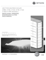
2. Function Principle
The diagram below shows the basic function of an Airmaster
air handling unit.
Bypass: Fresh air side
Bypass: Exhaust air side
1. Exhaust air (extraction from the room).
2. Exhaust lter M5.
3.
Counter-current heat exchanger(s): heat exchangers
eectively transfer heat energy from the exhaust
air to the supply air.
4. Exhaust air fan.
5. Motorised exhaust damper: shuts o the exhaust
side when the unit is stopped.
6. Exhaust air.
7. Outside air:
8.
Cooling module (option, not available with all
models): the cooling module reduces the outside
air temperature before the air passes into the air
handling unit.
9. Preheating surface (option): supports the de-icing
function.
10. Fresh air lter M5 (option: F7, F9).
11. Supply fan.
12. Motorised shut-o damper: shuts o the fresh air
side when the unit is stopped.
13. Comfort heater (option): equalises the minor tem-
perature loss in the heat exchanger (pos. 3).
14. Inlet (supply of heater outside air).
15. Modulating bypass (option): the bypass damper is
used to regulate the inlet air temperature.
The air temperature is monitored in the unit before and
after the heat exchanger in the exhaust and supply ducts.
The outside and cooling circuit temperatures are monitored
in the cooling module.

6
1
98 10
5
7
3
6
2
4
auto
3. Airlinq Viva (White Control
Panel)
3.1. Control Elements
1. Air ow setting (blue light) using a touch sensitive
control area, see page 8.
2.
Function button (manual start, manual stop, manual
temporary stop), see page 7.
3. USB mini-B port. To set or programme the air han-
dling unit, a PC is connected with “Airlinq User Tool”
or “Airlinq Service Tool” loaded. Download “Airlinq
User Tool” and “Airlinq Service Tool” at:
www.airlinq.eu
4.
Symbol “auto” for automatic operation (blue),
see page 7.
5. Holiday mode button, see page 9.
6. Symbol for holiday mode (blue), see page 9.
7.
Symbol for warnings (amber) and alarms (red),
see page 9.
8. Text “min” for minimal air ow.
9. Fan symbol.
10. Text “max” for maximum air ow.
3.2. Operation
3.2.1. Automatic Operating Lock
The control panel is tted with an automatic operating lock
to prevent accidental air ow setting, e.g. during cleaning.
The lock activates automatically after 30 seconds of no
operation.
Cancel automatic operating lock:
auto
Press for 1 second on the current air ow.
>> The automatic operating lock will cancel when the
air ow display is marked up to the current setting by
blue stripes.
3.2.2. Child Lock
The child lock prevents all operation. Operation of func-
tions with the child lock active will trigger 2 ashes of all
blue stripes on the air ow display (Pos. 1 under ”Control
Elements” on page 6).
Activate/cancel child lock:
Press “Function button” and “Holiday mode button”
simultaneously for 4 seconds (Pos. 2. and 5. under ”Control
Elements” on page 6).
>> All blue stripes on the air ow display will ash twice.
>> If operation is attempted with the child lock on,
all blue stripes on the air ow display will ash twice.

7
1.
auto
2.
3.
1. Start or restart automatic operation.
Press the function button.
>> The unit will start according to its programming if a start signal is active.
The control system will reactivate automatic operation after manual override.
The current air ow will be shown by a blue stripe. “Auto” will be shown
with a blue light.
Start operation manual.
Double press the function button.
>> The unit will start with standard air ow and standard inlet air temperature
(see page 19). “Auto” will be shown with a blue light. After 4 hours (time
can be adjusted to 0, 1, 2, ... 255 hours using a PC with Airlinq Service Tool
loaded) the unit will return to automatic operation.
2. Standby:
Press the function button when the unit is in operation.
>> The unit will stop for 1 hour (time can be adjusted to 0, 1, 2, ... 255 hours
using a PC with Airlinq Service Tool loaded) and then start at the next start
signal. Otherwise, the unit can be started earlier by using the function button.
The air ow indicator will ash slowly alongside minimum.
3. Switch o the unit:
Press the function button for min. 2 seconds to switch o the unit.
>> The unit must then be started using the function button. All lights on
the control panel will go out.
3.2.3. Start, Standby and Switch O
Airmaster’s air handling unit can be started and stopped
automatically or using the function button (pos. 2. under
”Control Elements” on page 6).
Automatic operation.
Automatic operation is started using a timer, night time
cooling, sensors, external contacts or an analogue BMS
system.
The current air ow and text “auto” are shown on the
control panel with a blue light above the fan symbol. (See
1st graphic below.)
Read also “Control system functions” on page 24.
Air ow can be over- or underridden manually. Automatic
operation is cancelled and the text “auto” will disappear.

8
_
+
auto auto
auto
3.2.4. Air Flow - Manuel Setting
Drag your nger on the setting area
clockwise to increase air ow or
counter clockwise to reduce air ow.
The light will follow your movement.
Lift nger from the area when the
required air ow is shown. The cur-
rent setting will then be shown again
with a single blue stripe.
After 12 hours (time can be adjusted
to 0, 1, 2, ... 255 hours using a PC with
Airlinq Service Tool loaded) the unit
will return to automatic operation.
Press the current air ow. The automatic operating lock will cancel
when the air ow display is marked up to the current setting by blue
stripes.
The same setting can be made by pressing the required air ow if the
automatic operating lock is not active.
Lift nger from the area when the
required air ow is shown. The cur-
rent setting will then be shown again
with a single blue stripe.

9
auto
auto
auto
0 2
2.
1.
3.
4.
4 6 8
3.2.5. Holiday Mode - Activation
Holiday mode is used as basic ventilation when the room
is unused for an extended period, e.g. holidays.
In holiday mode, the air handling unit will run with min.
air ow. The internal control function “Low temperature”
is active to protect the unit against ice formation. The
control function is able to activate the heating surfaces if
necessary. The internal control function “High temperature”
is deactivated in holiday mode.
See also “Internal Control Functions” on pages 26 and 27.
Activate holiday mode.
Press holiday mode button (pos. 5. under ”Control Elements”
on page 6) for 2 seconds.
>> The unit will go into holiday mode.
Cancel holiday mode:
Press the function button (pos. 2. under ”Control Elements”
on page 6).
>> The unit will return to automatic operation.
3.3. Warning and Alarm
The Airlinq control system monitors temperatures, air-
ow, cooling module function, lter status and various
components.
In the event of a fault, the control panel will show a yellow
or red symbol. The unit will maintain operation for yellow
warnings as best it can, whilst it will stop for red alarms.
Warnings and alarms are shown by ashes at various inter-
vals or a constant light. In the event of multiple faults, the
faults will be shown with a brief pause in between each one.
Warning and alarm displays (yellow and red):
Light signals for warnings and alarms:
1. Slow ash (2 seconds on 2 seconds o).
2. Rapid ash (0.5 seconds on, 0.5 seconds o).
3.
Rapid double ash (0.5 seconds on, 0.5 seconds o,
0.5 seconds on) at 2 second intervals.
4. Light on constantly.
See explanation of fault types on next page.
secs

10
Warning (yellow)
The air handling unit remains in operation in the event of a
warning, but can deviate from standard operation.
1. Slow ash:
Condensate - There is condensate in the cooling module
which has not been automatically removed. Module out
of operation.
•
Remove condensate manually from the condensate
tray.
•
Clean the condensate system (see page 28), or
CALL SERVICE.
2. Rapid ash:
Cooling module compressor locked (stopped). Module out of
operation. Condenser overheated for an extended period.
• Check whether the alarm cancels after power has
been cut o to the unit or CALL SERVICE.
3. Rapid double ash at 2 second intervals:
Filter needs replacing. Operation will continue unchanged.
• Change lters and cancel service (see page 29) or
CALL SERVICE.
4. Light on constantly.
Technical fault on temperature sensors (RT, OTV, CdT, OT,
EvT, EVi, EVo or HG), ow control or CO2 sensor. The cooling
module will be out of action if faults CdT, OT, EvT, EVi, EVo
or HG occur. Certain internal control functions are working
insuciently if faults RT and OTV occur.
• CALL SERVICE.
NB! A key to abbreviations is given in section
“Abbreviations” on page 36. Warnings and alarms
can also be read using “Airlinq User Tool” or “Airlinq
Service Tool”.
Alarm (red)
The air handling unit will stop to prevent damage in the
event of an alarm.
1. Slow ash:
Low temperature - Low outside temperatures can make
it necessary to protect the unit against ice formation. In
such instances, the low temperature alarm will activate.
The unit will automatically try to start up once every hour
if the start signal is still active.
2. Rapid ash:
Condensate - There is condensate in the air handling unit
which has not been automatically removed.
•
Remove condensate manually from the condensate
tray.
Units with no condensate drain:
•
If the alarm repeats, it may be necessary to install a
condensate drain or pump. CALL SERVICE.
Units with condensate drain/pump:
•
Clean the condensate system (see page 28), or
call service.
• The water lock is wrongly tted. Installation can be
corrected by authorised experts.
• Condensate pump defective. CALL SERVICE.
3. Rapid double ash at 2 second intervals:
Filter change required.
• Change lters and cancel service (see page 29) or
CALL SERVICE.
4. Light on constantly.
Critical fault on temperature sensors (IT, ETV) or a fan.
• CALL SERVICE.

11
1
6 8
3
7
45
2
9
“Selectable”
“Selected”.
“Increase” value.
“Reduce” value.
“Holiday mode” symbol shows for holiday mode
instead of fan symbol (pos. 7.), see page 24.
Padlock shows when operated with active
automatic operating lock and active screen lock.
"auto"
“Automatic operation” text o when manual
override or underride activated for air ow.
Touch screen
The Airlinq Orbit control panel is tted with a touch screen
operated in the same way as a smartphone. The control
surface is 52 x 52 mm. To change the display view, scroll on
either the left or right side of the control surface.
Screen displays and symbols adapt menus and functions
automatically.
In sect. “4.2. Operation” from page 11 to page 23 only the
most important content is shown on a white background
is shown on all screens.
4.2. Operation
4.2.1. Automatic Operating Lock
The control panel is tted with an automatic operation lock
to prevent accidental operation, e.g. caused by cleaning.
The lock activates automatically after 120 seconds of
no operation. The screen shows a padlock symbol with a
directional arrow at the bottom if operated.
Activate operation:
Press padlock and drag in direction of arrow.
To lock the screen against accidental operation, see sect.
”Lock Screen” on page 20.
4. Airlinq Orbit (Black Control
Panel)
4.1. Control Elements
1. Air ow setting (blue stripes), see page 12.
2. Function button (activate control menu, switch o
unit), see page 13.
3.
USB mini-B port. Connection to PC using “Airlinq
Service Tool”, to program the air handling unit.
Download “Airlinq Service Tool” at:
www.airlinq.eu
4.
Symbol for warnings (yellow) and alarms (red),
see page 23.
5. CO2 symbol, see ”CO2 status” on page 23.
6. Text “min” for minimal air ow.
7. Fan symbol.
8. Text “max” for maximum air ow.
9. Touch screen, see page 11.
Other symbols
“Auto”.
“Start”.
“Standby”.
“Switch o”.
“Conrm”.
“Back”.
“Cancel”.
“Help”.

12
_
+
autoauto
auto
4.2.2. Air Flow - Manuel Setting
Drag your nger on the setting area
clockwise to increase air ow or
counter clockwise to reduce air ow.
The light will follow your movement.
Lift nger from the area when the
required air ow is shown. The
current setting will then be shown
with 5 blue stripes.
After 12 hours (time can be adjusted
to 0, 1, 2, ... 255 hours using a PC
with Airlinq Service Tool loaded)
the unit will return to automatic
operation.
Cancel the operation lock or screen lock (if in use) and press the current
air ow until the air ow display is marked up to the current setting
with blue stripes.
The same setting can be made by pressing the required air ow until the
air ow display is marked up to the required setting with blue stripes.
Lift nger from the area when the
required air ow is shown. The
current setting will then be shown
with 5 blue stripes.

13
4.2.3. Automatic Operation
auto
Automatic operation is started using a timer, night time
cooling, sensors, external contacts or an analogue BMS
system.
The current air ow and text “auto” are shown on the control
panel with a blue light above the fan symbol.
Read also “Control functions” on page 24.
Air ow can be over- or underridden manually. Automatic
operation is cancelled and the text “auto” will disappear.
4.2.4. Operating Menu
Start the operating menu by pressing the function but-
ton (pos. 2 under ”Control Elements” on page 11). Press a
menu point to open the menu or activate/cancel a function.
Depending on the menu, related function elds will also be
changed. These can include text elds such as “Conrm”,
“Switch o”, “Cancel” or elds with symbols. Pop-up texts
can also appear for certain menus.
For group operation, see ”Airlinq BMS” on page 21.
4.2.4.1. Start and Standby
Start or restart automatic operation.
Press menu eld “ AUTO”.
>> The unit will start according to its programming if
a start signal is active, or automatic operation will be
reactivated after manual override. The current air ow
will show with 5 blue stripes. Text “auto” will show with
blue light.
Start operation manually.
Press menu eld “ START”.
>> The unit will start with standard air ow and standard
inlet air temperature (see page 19). Text “auto” will
show with blue light. After 4 hours (time can be adjusted
to 0, 1, 2, ... 255 hours using a PC with Airlinq Service
Tool loaded) the unit will return to automatic operation.
Standby.
Press menu eld “ STANDBY”, if the unit is in
operation.
>> The unit will stop for 1 hour (time can be adjusted
to 0, 1, 2, ... 255 hours using a PC with Airlinq Service
Tool loaded) and then start at the next start signal.
Otherwise, the unit can be started earlier by using the
operating menu. The air ow indicator will ash slowly
alongside minimum.
AUTO
START
STANDBY

14
4.2.4.2. O
Press menu eld “ OFF”
>> The control panel will show “SHUTDOWN?
AFTERWARDS THE SYSTEM HAS TO BE STARTED
MANUALLY.”, a tick for “Conrm” or a cross for “Cancel”.
Press the tick to switch o. (The unit must then
be started according to sect. ”Start and Standby”
on page 13. Press the cross to cancel switching o.
To switch o a unit, you can also press the function button
for 2 seconds (pos. 2 under ”Control Elements” on page 11).
4.2.4.3. Holiday Mode - Activation
In holiday mode, the air handling unit will run with min.
air ow. The internal control function “Low temperature”
is active to protect the unit against ice formation. The
control function is able to activate the heating surfaces if
necessary. The internal control function “High temperature”
is deactivated in holiday mode.
See also “Internal control functions” on pages 26 and 27.
Activate Holiday mode:
Press menu eld “ HOLIDAY MODE”
>> Holiday mode will activate. The holiday mode symbol
will show instead of the fan symbol.
Deactivate holiday mode:
To deactivate holiday mode, the unit must be started
according to sect. ”Start and Standby” on page 13.
4.2.4.4. Status
The Status menu is divided into 6 groups: Information,
Flow, Filters, Operation, Hardware and Installation Check.
The menu points indicate the unit’s operational status.
Press menu eld “ STATUS”
>> The sub-menu will activate.
Press the required sub-menu.
Information
Total Operation time The unit’s operation hours
since manufacture.
Panel SW Control panel software
version.
Control unit SW Control unit software version.
Control unit Serial Control unit serial number.
Service Contact address for technical
help and service. Can be
changed using Airlinq Service
Tool.
Flow
Requested Flow Air ow in %.
Supply Flow Supply Flow in m3/h.
Extraction Flow Exhaust ow in m3/h.
Supply Fan Supply fan RPM.
Extraction Fan Extraction fan RPM.
Filters
Current lter state Filter status indicator in %.
Operation since service No. of operation hours since
last lter change.
Next service Forecast of hours to next
lter change.
Approximated date Forecast (date) of next lter
change.

15
Operation
Started By Operation start signal
- “External”, using external contacts
and relays.
- “Airlinq”, manual start using a
control panel.
- “CO2”, using a CO2 sensor.
- “PIR”, using a passive infrared
sensor.
- “BMS”, using an analogue or digital
BMS system.
- “Timer”, using a timer.
- “Holiday mode”, via control panel or
a digital BMS system.
- “Dependent”, on several start
signals.
Operation State Operation status
- “Automatic”, fully automatic opera-
tion according to programming.
- “Manual”, when the automatically
set air ow or inlet temperature
is changed by the user or a BMS
system.
- “Night time cooling” is activated.
- “Holiday mode” is activated.
- “OFF”, the unit is switched o, and
must be started using the control
panel.
- “Standby”, the unit is temporarily
stopped and will start automatically
according to programming.
System Condition Active internal control system
function
- “Low temperature”.
- “High temperature”.
See “Internal control functions” on page 26.
Ext. Emergency Stop Emergency stop function
status On/O.
Inlet Temperature Inlet temperature in °C.
Outside Temp. AHU Outside temperature air
handling unit in °C.
Room Temperature Extraction temperature in °C.
Exhaust Temp. AHU Exhaust temperature air
handling unit in °C
Requested Temp. Setpoint Inlet temperature in
°C.
Operation
Max Room Temp. Setpoint “High room tem-
perature” in °C.
Pre Heater Connected in %.
Comfort Heater Connected in %.
Main Damper Status On/O.
Bypass Damper Bypass position in %. (0 =
closed; 100 = fully open)
Adaptive Inlet Signal voltage adaptive inlet
in Volts.
Supply Fan Signal voltage supply fan in
Volts.
Extraction Fan Signal voltage extraction fan
in Volts.
Cooling Module Operation in %.
Evaporator temp. Evaporator temperature in °C.
Condenser temp. Condenser temperature in °C.
Setpoint Cooling Mod. Cooling module temperature
setpoint in °C.
Outside Temperature Outside temperature cooling
module in °C.
Evaporator in Evaporator temperature “in”
in °C.
Evaporator out Evaporator temperature “out”
in °C.
Hot Gas Hot Gas temperature in °C.
Rel. humidity outside Relative humidity (outside
air) in %
Rel. humidity inside Relative humidity (exhaust
air) in %
AI#1 Analogue input 1 in Volts.
AI#2 Analogue input 2 in Volts.
AI#3 Analogue input 3 in Volts.
NB! If an option is not installed, no operation value
will show in the status menu.

16
Hardware
The condition of the individual components are monitored
and displayed in this menu.
Component functional = “OK”
Component with fault = “Fault”
Component not programmed = “N/A”
Components monitored:
Room temperature Room temperature sensor.
Inlet temperature Inlet temperature sensor.
Outside temperature Outside temperature sensor.
General.Purp.Temp. General purpose temperature
sensor.
Condenser Temp. Condenser temperature
sensor.
Evaporator Temp. Evaporator temperature
sensor.
Exhaust Temp. AHU Exhaust temperature sensor
air handling unit.
Outside Temp. AHU Outside temperature sensor
air handling unit.
Supply Flow Sensor 1 Supply Flow Sensor 1.
Supply Flow Sensor 2 Supply Flow Sensor 2.
Extraction Flow Sensor Extraction Flow Sensor.
CO2 Sensor CO2 Sensor.
Supply Fan Supply Fan.
Extraction Fan Extraction fan.
Evaporator In Temp. Evaporator inlet temperature
sensor.
Evaporator Out Temp. Evaporator outlet tempera-
ture sensor.
Hot Gas Temperature Hot gas temperature sensor.
CC Connection Data connection to the cool-
ing module.
CC Stepdriver Step driver cooling module.
CC Frequency Inverter Frequency inverter cooling
module.
Humidity Sensor (out) Humidity Sensor (outside).
Humidity Sensor (in) Humidity Sensor (inside).
Installation Check
All units in the Airlinq system are identied and shown
in the order it is programmed. The Installation check will
show the following:
This Unit Type of unit that shows the
”Installation check”; PC or ID
number of the control panel.
Expected AHU’s Number of air handling units
expected in the system.
Online AHU’s Number of online air handling
units.
Sub-menu ”Online AHU’S”
Group ”x”, ID ”y” All groups complete with
air handling unit ID (ID =
identication number);
x = 0, 1, 2, ... or 19, y = 0, 1, 2,
... or 19.
If cooling modules are
installed the text “+CC ID”
is shown together with the
identication number of the
cooling module; 100, 101,
102, ... or 119
.
Sub-menu ”Online Control Panels”
ID ”z” Identication number of all
online control panels; z = 160,
161, 162, ... or 179.
Sub-menu ”Group Master N/A”
Group ”x”, ID ”y” See description above.

17
4.2.4.5. Setup
All operational parameters can be changed under the “
SETUP” menu, according to local conditions.
Timers
TIMERCONTROLLED VENTILATION and
NIGHT TIME COOLING, set using the control panel or
“Airlinq User Tool”, starts and stops the air handling unit
using a timer. There are up to 7 dierent timer programs
for timer-controlled ventilation. All programs can be active
concurrently, and run after each other or override each
other.
Detailed function description available on page 24.
PROGRAM DISPLAY
NIGHT TIME COOLING
00:00
06:00
TIMER-CONTR. VENTILATION
FLOW: 100% TEMP 16⁰C
MO TU WE TH FR SA SU
07:00
17:00
07:00
17:00
FLOW: 80% TEMP 19⁰C
MO TU WE TH FR SA SU
FLOW: 30% TEMP 19⁰C
MO TU WE TH FR SA SU
ADD REMOVE
PROGRAMS DISPLAYED (examples)
Night time cooling:
Air ow (Flow) 100%, Inlet temperature (Temp) 16 °C,
Start: 00:00, Stop: 06:00,
Days: All days of the week (MO, TU, ..., SA, SU),
Program active (green point).
NB! Days for night time cooling cannot be adjusted.
Timer-controlled ventilation upper program:
Air ow (Flow) 80%, Inlet temperature (Temp) 19 °C,
Start: 07:00, Stop: 17:00,
Days: Monday to Friday (MO, TU, WE, TH, FR shown in
white text); Saturday and Sunday are programmed inac-
tive (SA and SU shown in light grey text),
Program active (green point).
Timer-controlled ventilation lowest program:
Air ow (Flow) 30%, Inlet temperature (Temp) 19 °C,
Start: 07:00, Stop: 17:00,
Days: Monday to Friday (MO, TU, WE, TH, FR shown in
white text), Saturday and Sunday are programmed inac-
tive (SA and SU shown in light grey text),
Program inactive (grey point).
Adjust a program
Press program.
>> Follow the guide on the next page.
Activate a program
Press the grey point on the right side of the program.
>> The point will change position upwards and go green.
NB! The most recently activated timer program dic-
tates operation of the air handling unit.
Deactivate a program
Press the green point on the right side of the program.
>> The point will change position downwards and go
grey.
Add a program for timer-controlled ventilation
Press “Add”.
>> Follow the guide on the next page.
Remove a program from timer-controlled ventilation
>> Follow the guide on the next page.

18
Adjust or add a program:
After selecting the program to be adjusted, or use of the
function button “Add” (see program view on previous page),
‘Setting’ mode will start.
MO TU WE TH FR SA SU
TIMER-CONTR. VENTILATION
START
FLOW %
TEMP °C
STOP
08:15
16:30
80
18
Increase/reduce a value:
Values can be set by pressing the right arrow (increase)
or left arrow (reduce).
Operation days are marked with a tick.
Make all settings and conrm by pressing the tick.
>> The program will be adjusted/added.
>> Display will return to “Program view”.
(See page 17)
Press the cross to cancel adjustment/adding.
Temperature setting:
The standard inlet temperature (default temperature)
is the setpoint for the unit’s required temperature level.
Standard setting is 19°C. The temperature can be set to
max. the required room temperature.
NB! The Airmaster unit can not be used to heat a room
by increasing inlet temperature. Room temperature
regulation must be performed using a heater installed
in the room.
Remove a program:
NIGHT TIME COOLING
00:00
06:00
TIMER-CONTR. VENTILATION
FLOW: 100% TEMP 16⁰C
MO TU WE TH FR SA SU
07:00
17:00
08:00
13:00
FLOW: 75% TEMP 19⁰C
MO TU WE TH FR SA SU
FLOW: 60% TEMP 18⁰C
MO TU WE TH FR SA SU
ADD REMOVE(1)
Programs for timer-controlled ventilation can be removed
from the list.
Press the square on the left of the program to be removed.
>> The program will be marked with a tick. The function
button “Remove” shows the number of programs to be
removed.
Press the function button “Remove” to remove the programs
selected or press the cross to cancel.
>> Programs will be removed.
>> Display will return to “Program view”.
(See page 17)
NB! Program “Night time cooling” cannot be removed.

19
Date and Time
Date and time are preprogrammed according to the calendar.
Time changes automatically to summer and winter times.
The summer/winter setting can be deactivated using the
Airlinq Service Tool.
The control system software date and time synchronises
automatically with date and time on a connected PC, but
can also be set directly.
Press Date or Time.
>> Set date or time.
Default Flow
The standard air ow (Default ow) is used by the Airlinq
control system when the air handling unit is started using
sensors or external contacts.
Press Default Flow.
>> Set Default Flow in % (Default 80%).
Default Temp
The standard inlet temperature (default temp) is the
setpoint for the unit’s required temperature level. Standard
setting is 19°C. The temperature can be set to max. the
required room temperature.
NB! The Airmaster unit can not be used to heat a room
by increasing inlet temperature. Room temperature
regulation must be performed using a heater installed
in the room.
Press Default Temp.
>> Set inlet temperature in°C (Default 19 °C).
High Temperature
High temperature is programmed at 25°C. At this room
temperature, the upper limit of the temperature range
described as “comfort temperature” is exceeded.
If the unit detects that this limit is exceeded when in
operation, its control system will start a cooling process to
reduce the current room temperature. See “Internal control
functions - high temperature” on page 27.
This temperature setting does not generally need to be
changed.
Press High Temperature.
>> Set high room temperature in°C (Default 25 °C).
NB! To ensure trouble-free operation, we recommend
programming high room temperature higher than the
normal room temperature.
Reset Service
After a regular service with lter change, the lter change
timer must be reset.
Press Reset Service.
>> Set code (Standard “9732”) and conrm. See sect.
“4.2.4.6. Lock Screen” on page 20.
Data Log
Airmaster units have a continuous data log. When the
memory is full, the oldest data is overwritten rst.
If a fault is detected on the unit, a time-limited data log
can be activated.
Press Data Log
>> Set log interval (log period is calculated automatically),
or set log period (log interval is calculated automatically).
>> Activate data log - All data in the memory is deleted,
and the data log started.
When the data log is completed, a pop-up text appears on
the control panel:
“Time-limited data log completed. Download data to a
PC with Airlinq Service Tool”
The log period depends on the logged parameters. In the
event of rarely-occurring faults, the interval or period can be
extended, and in the event of frequent faults, the interval
can be shortened. After transfer to a PC, the data log can be
automatically sent for analysis by (e.g.) your service partner.
Please contact your service partner by phone or mail to
agree service provision.

20
Startup Guide
The startup guide starts automatically when the unit is
started for the rst time. The guide can also be started
manually subsequently (menu under “Setup”), e.g. to retro-
install a CO2 sensor.
The most important settings can be made using the startup
guide. The guide must be run completely. When making
settings, the guide jumps automatically to the appropriate
menu point and back.
Startup guide menu points:
• Set Default Flow, see page 19.
• Set Default Temp, see page 19.
• Set High Temperature, see page 19.
• Set Date and Time, see page 19.
•
Set Night Time Cooling and Timer-Controlled
Ventilation, see page 17.
• Set CO2 level lower limit and upper limit and Start/
Stop of the unit with CO2 sensor, see page 25.
•
Set the code for the screen lock and the Service
Reset, see page 20.
• Set the activation of the screen lock, see page 20.
•
Start unit (starts the unit with the current program-
ming and terminates the startup guide).
4.2.4.6. Lock Screen
The control panel can be locked to prevent accidental
operation using the screen lock.
Activate screen lock:
Press “ LOCK SCREEN”.
>> The screen will lock immediately. The control panel
will show the main screen.
The screen lock is protected by a 4 digit code (Default:
“9732”). The code can be changed and the activation of
the screen lock can be changed to manual, automatic or
inactive by using the Startup Guide or the programs Airlinq
User Tool and Airlinq Service Tool.
Deactivate the screen lock:
Press padlock on the control panel main screen and drag
in direction of arrow.
Set code:
0 0 0 0
Set code by pressing the up arrow to increase the value,
and down arrow to reduce it.
Press tick.
>> The screen will be unlocked.
4.2.5. CO2 Status
LEVEL
756 PPM
If the unit has a CO2 sensor, the room’s current CO2 level will
be shown on the control panel.
When the sensor sends a signal to the unit, the CO
2
symbol
will show on the control panel main screen. The symbol will
be green, amber or red depending on level.
Press symbol (pos.5 under ”Control Elements” on page 11).
>> CO2 status will be shown.
/