Page is loading ...

Document no.: 3063527_201308 Subject to technical modications. GB
Wolf GmbH · Postfach 1380 · D-84048 Mainburg · Tel. +49 (0)8751/74-0 · Fax +49 (0)8751/741600 · Internet: www.wolf-heiztechnik.de
Operating instructions
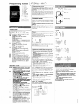
Control unit - CGL
20.0 °C
Friday
31/10/08
12 : 16
Zone 1

3063527_2013082
Table of contents
Safety instructions, service / repair .............................................................................. 4
Standards and regulations ........................................................................................... 5
Unit description / disposaland recycling ..................................................................... 6
Zoning .............................................................................................................................. 7
Installation as an external remote control ................................................................... 8
Electrical connection ..................................................................................................... 8
BML overview ................................................................................................................. 9
Control level 1 .......................................................................................................... 10-13
L.h. rotary selector, program selection ....................................................................... 10
R.h. rotary selector ..................................................................................................... 10
Program selection ................................................................................................. 10-11
Automatic mode ................................................................................................... 10
Manual mode.........................................................................................................11
Ventilation mode ....................................................................................................11
Standby mode .......................................................................................................11
Info key ................................................................................................................. 11-12
Temperature selection key ......................................................................................... 12
Speed adjustment key ............................................................................................... 12
Display explained ......................................................................................................... 13
Control level 2 .......................................................................................................... 14-24
Main menu overview .................................................................................................. 14
Displays ..................................................................................................................... 15
Acknowledge faults .................................................................................................... 15
Basic settings ............................................................................................................. 16
Language ............................................................................................................. 17
Date ...................................................................................................................... 17
Time ..................................................................................................................... 17
Automatic summertime......................................................................................... 18
Key lock ................................................................................................................ 18
Zone Z1 ................................................................................................................ 19
Day temperature................................................................................................... 19
Economy temperature for heating ........................................................................ 19
Backup temperature for heating ........................................................................... 19
Speed adjustment ................................................................................................ 20
Setback mode program ........................................................................................ 20
Supply air minimum limit ...................................................................................... 20
Enable night ventilation ........................................................................................ 21
Time program ............................................................................................................. 21
Switching times, factory setting ............................................................................ 22
Holiday program ......................................................................................................... 23
Specialist .................................................................................................................... 24

3063527_201308
3
Control level 3 .......................................................................................................... 24-32
Code scan .................................................................................................................. 24
New conguration / Sensor check ............................................................................. 24
Zone designat ............................................................................................................ 24
Ventilation unit parameters ........................................................................................ 25
Relay test ................................................................................................................... 25
Zone reset .................................................................................................................. 25
Setting parameters ....................................................................................................... 26
Specialist parameter list - overview ...................................................................... 26-27
Parameters / function description ......................................................................... 28-32
Master reset / standard functions .......................................................................... 33-34
Motor protection ......................................................................................................... 33
Room frost protection ................................................................................................. 33
Central heating backup mode .................................................................................... 34
Supply air minimum limit for heating .......................................................................... 34
Filter contamination fault trigger ................................................................................. 34
Active lter monitor .................................................................................................... 34
Fan run-on time .......................................................................................................... 34
External ON/OFF ....................................................................................................... 34
Additional functions ................................................................................................ 34-36
Room/supply air cascade control ............................................................................... 35
Night ventilation ......................................................................................................... 35
Preheater coil, HR ice guard ...................................................................................... 36
Condensate overow ................................................................................................. 36
Summer shutdown ..................................................................................................... 36
Heat recovery ............................................................................................................. 36
HR ice guard .............................................................................................................. 36
Fire alarm ................................................................................................................... 36
CO
2
control ..................................................................................................... 31, 32, 37
Sensor resistances....................................................................................................... 37
Specication ................................................................................................................. 38
System conguration ................................................................................................... 39
Terminal assignments .................................................................................................. 40
Fault messages........................................................................................................ 41-43
Wiring diagram ........................................................................................................ 44-47
Menu structure ......................................................................................................... 48-51
Table of contents

3063527_2013084
Safety instructions
The following symbols are used in this instruction manual. This
important information concerns personal as well as operational
safety.
"Safety instructions" must be complied with to the letter, to prevent
risks and injuries to individuals and material losses on the appliance.
Danger through 'live' electrical components!
Please note: Turn off the ON/OFF switch before removing the
casing.
Never touch electrical components or contacts when the ON/OFF
switch is in the ON position. This would lead to a risk of electrocution
that may lead to injury or death.
"Note" indicates technical instructions that must be observed to
prevent material losses and equipment malfunctions.
Even when the unit has been shut down, voltage will still be present
at terminals and connections of the EC fans. This means there is
a risk of electric shock that could result in injury or death.
Never touch the EC fans until ve minutes after disconnecting the
power across all poles have elapsed.
Please note
Safety instructions
Service / Repair
- Regularly check the perfect function of all electrical equipment.
- Only qualied personnel may remove faults or repair damage.
- Only replace faulty components or equipment with original Wolf
spare parts.
- Observe specied electrical fuse ratings (see specication).
Any damage or loss resulting from technical modications to Wolf
control units is excluded from our warranty.
Please note
Service / Repair

3063527_201308
5
Standards / Regulations
- According to DIN EN 50110-1, only qualied electricians may
carry out the installation and commissioning of the ventilation
control unit and connected accessories.
- Observe all regulations stipulated by your local power supply
utility and all VDE or local regulations.
- DIN VDE 0100 regulations regarding the installation of high
voltage systems up to 1000 V
- DIN VDE 0105-100 Operation of electrical plants
- Use exclusively original Wolf accessories (electric heater coil,
condensate pump, servomotors, etc.), otherwise the Wolf
warranty will be void.
Only use cables that meet local wiring regulations with regard to
voltage, current, insulation material, load etc. Always t an earth
conductor.
Power supply:
An externally accessible, omnipolar isolator must be installed
with the appliance. Power cable, external: 3 x 2.5 mm².
Fuse/MCB protection: 230 V/16 A.
RCD
Only AC/DC-sensitive RCDs of type B with 300 mA rating are
permissible.
Connect the power cable and accessories in accordance with
the wiring diagram provided.
A high leakage current can be expected due to the EC
motors. Ensure that a secure earth connection is in place
before connecting the power supply and commencing
commissioning.
For Austria, the ÖVE regulations and local building regulations
apply.
Installation /
Commissioning
Warnings - Removing, bypassing or disabling of safety and monitoring
equipment is not permissible.
- The system must only be operated if it is in perfect technical
condition. Immediately have any faults and damage that may
impact on safety removed.
The appliance and control unit accessories comply with the
following regulations:
EC Directives
- 2006/95/EC Low Voltage Directive
- 2004/108/EC EMC Directive
EN Standards
- EN 60730-1 Automatic electrical controls for household and
similar use
- EN 60730-2-11 Particular requirements for temperature
sensing controls
- EN 61000-6-2 EMC Immunity for industrial environments
- EN 61000-6-3 EMC Emission standard for residential
environments
Standards / Directives

3063527_2013086
The control panel is designed for regulating large area ventilation
units with variable speed EC motors.
Other functions
- HR control 0 - 10 V
- CO
2
-based fan speed matching
- Electric reheater coil: variable control 0 - 10 V
- Room / supply air cascade control or supply air control
- Night ventilation
- Electric preheater coil:
Switching ON/OFF by outside temperature
The control unit can be operated with the programming module
for ventilation units (BML programming module, material number
2744634). The BML programming module can also be used to
program switching times, to modify parameters and to display
fault messages.
The control unit has an eBUS interface and can therefore be fully
integrated into the Wolf control system.
There can only be one BML in any one system (eBUS).
Up to 7 CGL units can be operated with one programming unit.
Please note
Unit description
Unit description
Observe the following information regarding the disposal of faulty
system components or the system at the end of its service life:
Dispose of all components in accordance with applicable
regulations, i.e. separate material groups correctly. The aim should
be the maximum possible amount of basic materials recycled and
the lowest possible environmental impact.
Never dispose of electrical or electronic scrap through household
waste, but recycle it appropriately.
Generally, dispose of materials in the most environmentally
responsible manner according to environmental, recycling and
disposal standards.
Disposal and recycling
The ventilation unit is designed for air intake temperatures between
-20 °C and +40 °C. Only store the ventilation unit in dry conditions
at an ambient temperature between -25 °C and +55 °C.
Wolf CGL ventilation units are designed to heat and lter normal
air. The use of these units in wet rooms or rooms with explosive
atmospheres is not permissible. Handling very dusty or aggressive
media is not permissible.
Any on-site modication or unintended use of the unit is not
permissible and Wolf GmbH accepts no liability for any damage
caused as a result.
Intended use

3063527_201308
7
Zoning
Zoning
When more than one CGL is controlled with one programming unit,
the zone for each appliance must be set using the DIP switches
on the control PCB (in the control panel).
If only one zone is to be connected, the following chapter can
be skipped.
Multiple zones in one
system
The three switches on the left hand side of the 4-position DIP switch
can be used to assign the ventilation unit to a zone.
Up to seven zones are possible in one system.
Zone setting
Zone 1
Zone 2
Zone 3
Zone 4
Zone 5
Zone 6
Zone 7
Fig.:
DIP switches on the
control PCB
DIP switches
Control PCB
X1
Never pull out the coding card X1, otherwise malfunctions may
result.
Please note

3063527_2013088
Installation as an external remote
control
Wall mounting base
installation
- Remove the wall mounting base from its packaging.
- Secure the wall mounting base on a ush-mounting box
(Ø 55 mm) or directly on the wall.
Wall mounting base
Fixing holes
Fixing holes
Installation of BML on wall mounting base
Wall mounting base
Mat. no. 2744275
60
100
Electrical connection of
remote control
- The electrical connection must be carried out only by a qualied
electrician.
- Never route sensor leads alongside mains power cables.
- Use the repair switch to switch off the power supply
- Wire the wall mounting base with a four-core cable (minimum
cross-section 0.5 mm²) in accordance with the diagram
eBUS
Terminal strip
Wall mounting base
+ -
+ -
Recommended cables
and
minimum cable
cross-sections:
H05VV-F 3 x 2.5 mm² power cable (230 V)
H05VV-F 4 x 1.0 mm² Open/Close servomotor 230 V
H05VV-F 2 x 0.5 mm² BUS cable (<400 m length)
Fuse/MCB protection: Power supply 230 V 1 x 16 A
ϑ
Outside temperature sensor

3063527_201308
9
BML overview
L.h. rotary selector R.h. rotary selector
Info key
Temperature
adjustment
Speed adjustment
DisplayStatus indicator
Minimum fresh air proportion
(no function)
20.0 °C
Friday
31/10/08
12 : 16
Zone 1
Room temperature / extract air temperature
Time alternating with
outside temperature

3063527_20130810
Program selection
You can select the programs listed below by turning the l.h. rotary
selector.
The arrow on the l.h. edge of the display points to the selected
program.
R.h. rotary selector
The right hand rotary selector is used for all programming steps.
Turning the rotary selector enables you to select the required
menu item.
Pressing the r.h. rotary selector conrms the programming step.
L.h. rotary selector, program selection
This rotary selector enables the program to be selected. The rotary
selector can be rotated indenitely, without an end stop. You will
feel it click into each position as it rotates. The selected function
is indicated by an arrow in the display.
Control level 1
Automatic mode
Ventilation according to a time switch program. Call-up of HR,
reheater and fan according to demand.
As shown in the diagram, you can preselect the operating mode
via the time program when the system has been switched off.
06:00
22:00
On
Off
„Day mode”
Time
Setback mode program
Selection:
- Economy operation
- Backup mode (factory setting)
- Standby
- Summer ventilation
Backup mode Backup mode
07:00
14:00

3063527_201308
11
Control level 1
Manual mode
The ventilation time program is inactive. With this setting, ventilation
is enabled 24 hours a day. The set value from day mode is active.
The speed can be preselected manually or varied according to
CO
2
content. Activation of HR and reheater according to demand.
Ventilation mode
Ventilation according to the time switch program.
Fans start, and the speed of the ventilation units can be preselected
manually. This can be used to ensure an adequate air ow rate
through the room during the warmer months.
HR and the reheater are switched off.
The outside air dampers are opened.
Ventilation is disabled below an outside temperature of 7 °C.
Standby mode
Fan and actuating signal are switched off; room frost protection
remains active.
System start or stop is actuated via an air quality sensor (parameter
LM163 must be set to ON).
The CO
2
sensor should be placed inside the room for this operating
mode.

3063527_20130812
Control level 1
i
1 Operating mode
2 Current program
3 Extract air temp
4 Set room heating
5 Outside temperature
6 Actual vent air
temperature
Zone 1
Back
Operating mode
Ex. air temp.
Set room htg.
Outside temp
Act. vent air t
Curr program
Temperature selection key
Please note:
Pressing the key enables quick correction of the set room
temperature (or the supply/extract air temperature). You can turn
the r.h. rotary selector to raise or lower the required temperature
by up to 4 K. The bar on the display moves to the left or the right
depending on the direction the selector is turned. Press the r.h.
rotary selector to conrm the modied value.
Zone 1
Temperature
selection
0.0 K
0
Speed adjustment key
Please note:
Pressing the key displays the current speed. You can then turn the
r.h. rotary selector to modify the speed to a value between 30 and
100 %. Press the r.h. rotary selector to conrm the modied value.
The speed preselected here (the base speed) cannot be reduced
by the CO
2
sensor.
Zone 1
Speed adjust
30.0 %
Info key
Please note: In the case of more than one zone (up to 7), rst
select the zone for which the values are to be scanned.
You can use the Info key to display current temperatures and system
values. Turning the r.h. rotary selector displays the following values.
Fire alarm
Fault zone
Frost protection room
External ON/OFF
Filter check
Standby
Summer ventilation
VA min limit heating
Night ventilation
Room temperature reached
Outside temperature shutdn
Control operation

3063527_201308
13
Display explained
Room temperature, supply air temperature, extract air
temperature
The temperature shown on the display depends on the temperature
sensors connected. The sensor value displayed is as follows:
Only supply air sensor connected: display of supply air temperature
Only room sensor connected: display of room temperature
Supply air sensor + room sensor connected:
display of room temperature
Supply air sensor + extract air sensor connected:
display of extract air temperature
Time and outside temperature
The time and the outside temperature are displayed alternately
(subject to an outside temperature sensor being installed).
Day / date
Display of the currently set day and date.
Status display
Symbols indicate the current operating state of your
ventilation system.
Clock = ventilation mode (heating) with time program
Manual = ventilation mode (heating) without time program
House = ventilation mode (summer mode)
with time program
Standby = system off or ventilation
(heating) ON/OFF via CO
2
sensor if
parameter LM163 set to ON
Indication of the current zone
If more than one zone is connected (up to 7)
you can select the zone you want by turning the r.h. rotary
selector.
20.0 °C
Friday
31/10/08
12 : 16
Zone 1
20.0 °C
Friday
31/10/08
10.0 °C
Zone 1
20.0 °C
Friday
31/10/08
12 : 16
Zone 1

3063527_20130814
Control level 2 - Main menu
Back to the default display
Pressing the r.h. rotary selector calls up control level 2, where
you can select the menu levels shown in the overview by turning
the rotary selector clockwise. After selecting the parameter, you
enter the submenu by pressing the r.h. rotary selector again.
Pressing the Info key takes you back to the default display,
irrespective of which submenu is currently displayed.
The system also returns to the default display automatically when
no adjustment is made for more than one minute.
Overview
All available set and actual temperatures, the operating mode and
other system values can be displayed.
This is explained in the „Displays“ chapter.
Displays
Acknowledging (resetting) faults that have occurred.
This is explained in the „Acknowledge faults.“ chapter.
Acknowledge faults
Setting of the most important parameters in the ventilation system
such as time, date, room temperature, night temperature, supply
air minimum limit for heating, backup temperature, night setback,
and night ventilation.
Setting options and explanations of the individual parameters are
given in the "Basic settings" chapter.
Basic settings
Modication of the time switch programs for heating operation.
Setting options and how to modify the individual time programs
are explained in the "Time programs" chapter.
Time programs
Setting the specialist's parameters for the ventilation system.
Setting options and explanations of the individual parameters are
given in the "Specialist" chapter.
Specialist
Five different holiday programs can be set. The holiday program
takes precedence over the normal switching time.
When the holiday program ends, the system returns to the previously
set time program automatically.
Holiday program
Main menu
Back
Fault ackn.
Basic settings
Time program
Holiday prog
Specialist
Back
Displays

3063527_201308
15
Displays Press the r.h. rotary selector to change to control level 2.
Turn the r.h. rotary selector clockwise to select the „Displays“
menu level and conrm the selection by pressing the r.h. rotary
selector again.
You can now display the following values in sequence by
turning the r.h. rotary selector.
Always select the zone rst in order to scan its values.
Control level 2 - Displays - Fault acknowledge
1 Operating mode
2 Current program
3 Extract air temperature
4 Set room heating
5 Outside temperature
6 Actual vent air temperature
7 Set vent air temperature
8 Motor speed
9 Heating mixer
10 Heat recovery
11 Conguration
12 Softwareversion LM x
Softwareversion LM y
Any sensors that are not connected are skipped, as only
available values can be displayed.
Acknowledge faults
Press the r.h. rotary selector to change to control level 2. Turn
the r.h. rotary selector clockwise to select the „Acknowledge
faults“ menu level and acknowledge faults by pressing the r.h.
rotary selector again.
After acknowledging faults, the display returns to the standard
mask immediately.
Main menu
Back
Fault ackn.
Basic settings
Time program
Holiday prog
Specialist
Back
Displays
Main menu
Back
Fault ackn.
Basic settings
Time program
Holiday prog
Specialist
Back
Displays

3063527_20130816
Parameter Setting range Factory setting Individual
settings
Language German / English
French / Dutch
German
Date --.--.--
Time 0 to 24 h
Auto summertime AUTO / OFF AUTO
Key lock ON/OFF OFF
Z1 Zone 1 . . Z7 Zone 7
Day temperature 5 °C – 50 °C 20 °C
Economy temperature for
heating
5 °C – 30 °C 16 °C
Backup temperature for
heating
5 °C – 30 °C 12 °C
Speed adjustment 30 - 70 % 40 %
Setback program Econ. operation
Backup mode
Standby
Hols summer vent
Backup mode
VA min limit 5 °C – 30 °C 16 °C
Night ventilation enable ON/OFF ON
Parameter overview, default settings
(settings and functions on the following pages)
Control level 2 - Default settings
Main menu
Back
Fault ackn.
Basic settings
Time program
Holiday prog
Specialist
Back
Displays

3063527_201308
17
Control level 2 - Default settings
Language
Press the r.h. rotary selector to change to control level 2.
Turn the r.h. rotary selector clockwise to select the "Default
settings" menu level and conrm the selection by pressing the
r.h. rotary selector again.
Select the Language parameter by turning the rotary selector
further clockwise, and conrm your selection by pressing the
selector again.
The language is changed by turning the r.h. rotary selector and
pressing to conrm.
You can cancel your input by pressing the „Speed adjustment
key “.
Factory setting: German
Options: German / English
French / Dutch
Basic settings
Back
Language
Date
Time
Autom. summert.
Key lock
Z1 Hall1
Press the r.h. rotary selector to change to control level 2.
Turn the r.h. rotary selector clockwise to select the "Default settings"
menu level and conrm the selection by pressing the r.h. rotary
selector again. Select the Date parameter by turning the rotary
selector further clockwise, and press selector to conrm.
Turn the r.h. rotary selector to change the date.
Enter the day, month and year one after the other, pressing the
r.h. rotary selector each time to conrm.
You can cancel your input by pressing the „Speed adjustment key“.
The date will be displayed automatically if a radio clock module is
connected. However, the date cannot then be changed.
Date
Basic settings
Back
Language
Date
Time
Autom. summert.
Key lock
Z1 Hall1
Press the r.h. rotary selector to change to control level 2. Turn the
r.h. rotary selector clockwise to select the "Default settings" menu
and conrm the selection by pressing the r.h. rotary selector again.
Select the Time parameter by turning the rotary selector further
clockwise, and press selector to conrm.
Then turn the r.h. rotary selector to change the time.
Enter the hours, minutes and seconds one after the other, pressing
the r.h. rotary selector each time to conrm.
You can cancel your input by pressing the „Speed adjustment key”.
You must set the time again if the control unit has been disconnected
from the power supply longer than 48 hours.
The time will be displayed automatically if a radio clock module is
connected. However, the time cannot then be changed.
Time
Basic settings
Back
Language
Date
Time
Autom. summert.
Key lock
Z1 Hall1

3063527_20130818
Control level 2 - Default settings
Automatic summer time
Turn the r.h. rotary selector further clockwise to select the „Autom.
summert.“ parameter and conrm the selection by pressing the
r.h. rotary selector again.
„Automatic summertime“ is disabled by turning the r.h. rotary
selector and by pressing to conrm.
Factory setting: auto.
Options: auto / off
Key lock Press the r.h. rotary selector to change to control level 2. Turn
the r.h. rotary selector clockwise to select the "Default settings"
menu level and conrm the selection by pressing the r.h. rotary
selector again. Select the "Key lock" parameter by turning the
rotary selector further clockwise, and press selector to conrm.
The key lock is activated by turning the r.h. rotary selector and by
pressing to conrm.
You can cancel your input by pressing the „Speed adjustment key“ .
Note:
The key lock parameter is intended to prevent unintentional
adjustment of the ventilation system.
If the key lock parameter is set to "ON", the key lock will be activated
automatically one minute after the last adjustment.
No adjustments or scans can be implemented when the key lock
is enabled. If, nevertheless, a key or rotary selector is activated,
then the display shows KEY LOCK.
The key lock can be lifted for a single adjustment or to display
the set/actual values by holding down the r.h. rotary selector for
approx. three seconds.
To disable the key lock permanently, the "Key lock" parameter
must be set to "Off" again.
Function keys remain active
Speed adjust , fresh air proportion adjustment and temperature
correction).
Please note
Factory setting: off
Options: on / off
Basic settings
Back
Language
Date
Time
Autom. summert.
Key lock
Z1 Hall1
Basic settings
Back
Language
Date
Time
Autom. summert.
Key lock
Z1 Hall1

3063527_201308
19
Control level 2 - Default settings
Select "Z1 Zone 1". If there is more than one zone in the
system, select the zone for which you want to change values
(max. 1-7) and conrm your selection by pressing the r.h. rotary
selector again. You can now modify the following values for
the selected zone one after the other by turning the r.h. rotary
selector.
Select and conrm Day temperature using the r.h. rotary
selector. Turn the r.h. rotary selector to set the required
temperature and then press to conrm.
Tagtemperatur
[Day temperature]
Factory setting: 20 °C
Range: 5 - 50 °C
Economy temperature
Heating
Select and conrm Economy temperature heating using the r.h.
rotary selector. Turn the r.h. rotary selector to set the required
economy temperature and press selector to conrm.
Factory setting: 16 °C
Range: 5 - 30 °C
Backup temperature
Heating
Select and conrm Backup temperature heating using the r.h.
rotary selector. Turn the r.h. rotary selector to set the required
backup temperature for heating and press selector to conrm
(see "Standard functions" - "Central heating backup mode").
Factory setting: 12 °C
Range: 5 - 30 °C
Basic settings
Back
Language
Date
Time
Autom. summert.
Key lock
Z1 Zone 1
Basic settings
Back
Day temperature
Econ temp htg
Backup temp htg
Speed adjust
Setback prog
Back
Basic settings
Back
Day temperature
Econ temp htg
Backup temp htg
Speed adjust
Setback prog
Back
Basic settings
Back
Day temperature
Econ temp htg
Backup temp htg
Speed adjust
Setback prog
Back
Z1 Zone 1

3063527_20130820
Control level 2 - Default settings
Speed adjustment Select and conrm Speed adjustment using the r.h. rotary
selector. Turn the r.h. rotary selector to set the required speed
(30-70 %) and press selector to conrm.
Function:
The speed preselected here applies during day temperature,
backup mode, Summer ventilation and night ventilation and
cannot be reduced by the CO
2
sensor.
Factory setting: 40 %
Range: 30 - 70 %
Basic settings
Back
Day temperature
Econ temp htg
Backup temp htg
Speed adjust
Setback prog
Back
Setback
program
Select and conrm Setback prog. using the r.h. rotary selector.
Turn the r.h. rotary selector to set the required operating mode,
and press selector to conrm:
- Backup mode
- Economy operation (setback mode)
- Standby
- Summer ventilation
.
You can preselect the above operating modes when the time
program has switched off the system.
Backup mode function:
Backup mode can become active when the time program
switches the system off (this is the factory setting). If the
temperature in the room falls below the set backup temperature,
the fan, HR and reheater are activated until the backup
temperature is reached (+/- 1 K).
Backup mode = Economy mode: In the periods when the
system is not switched on by the time program, the fan is only
activated if the temperature falls below the backup temperature.
Factory setting: Backup mode
Range: Backup mode
Econ.operation
Standby
Summer ventil.
Basic settings
Back
Day temperature
Econ temp htg
Backup temp htg
Speed adjust
Setback prog
Back
Supply air minimum limit Select and conrm VA min limit using the r.h. rotary selector.
Turn the r.h. rotary selector to set the required supply air
minimum temperature and press selector to conrm.
Function:
The air blown into the room must be at or above this
temperature at all times. If the temperature falls below the set
value by the set hysteresis (2 K), HR and the reheater are
activated.
Please note:
The set temperature (for day, economy temperature) cannot be
set below the value of the minimum limit.
Factory setting: 16 K
Range: 5 - 30 K
Basic settings
Back
Econ temp htg
Backup temp htg
Speed adjust
Setback prog
VA min limit
Nght vent enable
/