Carlisle Smart Pumps EV2-30 Owner's manual
- Type
- Owner's manual
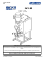
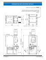
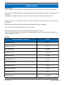
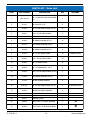
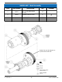
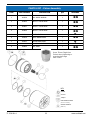
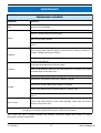
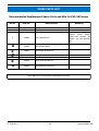
Carlisle Smart Pumps EV2-30 are great for use with solvent and water-based materials in hazardous areas such as Zone 1, with a protection level of Ex h IIB T4 Gb X (pump), II 2 G Exd/Exde IIB T4 IP55 (motor), and II 2 GD ck T4 (gearbox). They have a nominal pump stroke of 50mm, a maximum fluid pressure of 20bar, and a nominal flow volume per cycle of 0.75 l/m. Fluid output at 20 Hz is 7.5 l/m, and at 80 Hz is 30 l/m.
Carlisle Smart Pumps EV2-30 are great for use with solvent and water-based materials in hazardous areas such as Zone 1, with a protection level of Ex h IIB T4 Gb X (pump), II 2 G Exd/Exde IIB T4 IP55 (motor), and II 2 GD ck T4 (gearbox). They have a nominal pump stroke of 50mm, a maximum fluid pressure of 20bar, and a nominal flow volume per cycle of 0.75 l/m. Fluid output at 20 Hz is 7.5 l/m, and at 80 Hz is 30 l/m.


-
 1
1
-
 2
2
-
 3
3
-
 4
4
-
 5
5
-
 6
6
-
 7
7
-
 8
8
-
 9
9
-
 10
10
-
 11
11
-
 12
12
-
 13
13
-
 14
14
-
 15
15
-
 16
16
-
 17
17
-
 18
18
-
 19
19
-
 20
20
-
 21
21
-
 22
22
-
 23
23
-
 24
24
-
 25
25
-
 26
26
-
 27
27
-
 28
28
-
 29
29
-
 30
30
-
 31
31
-
 32
32
-
 33
33
-
 34
34
-
 35
35
-
 36
36
-
 37
37
-
 38
38
-
 39
39
-
 40
40


Carlisle Smart Pumps EV2-30 Owner's manual
- Type
- Owner's manual
Carlisle Smart Pumps EV2-30 are great for use with solvent and water-based materials in hazardous areas such as Zone 1, with a protection level of Ex h IIB T4 Gb X (pump), II 2 G Exd/Exde IIB T4 IP55 (motor), and II 2 GD ck T4 (gearbox). They have a nominal pump stroke of 50mm, a maximum fluid pressure of 20bar, and a nominal flow volume per cycle of 0.75 l/m. Fluid output at 20 Hz is 7.5 l/m, and at 80 Hz is 30 l/m.
Ask a question and I''ll find the answer in the document
Finding information in a document is now easier with AI
Related papers
-
Carlisle IntelliSpray IS40 Owner's manual
-
-
-
-
-
-
-
-
-
Other documents
-
Global Industrial 293224 User manual
-
 Macnaught L-BG18V User manual
-
 Binks Smart Pumps User manual
-
 Binks Smart Pumps User manual
-
 Northern Industrial Tools Please see replacement Item# 58082. 50:1 Grease Pump Owner's manual
-
 DESTACO CAMCO RNG Series User manual
-
 Binks E4-60 User manual
-
 Macnaught K4-01 User manual
-
Binks DX200 3:1 Ratio Diaphragm Pump User manual
-
Lincoln 1882 Owner's manual


