Page is loading ...

PN: 53040:A ECN 07-072
Deluge • Preaction Control
MRP-2001 & MRP-2001E
Installation, Operation and Programming Manual
Document #53040
4/16/07 Revision:
A

PrecauLarge.PMD 02/26/2007
An automatic fire alarm system–typically made up of
smoke detectors, heat detectors, manual pull stations,
audible warning devices, and a fire alarm control panel with
remote notification capability–can provide early warning of a
developing fire. Such a system, however, does not assure
protection against property damage or loss of life resulting
from a fire.
The Manufacturer recommends that smoke and/or heat
detectors be located throughout a protected premise follow-
ing the recommendations of the current edition of the
National Fire Protection Association Standard 72 (NFPA 72),
manufacturer's recommendations, State and local codes,
and the recommendations contained in the Guides for
Proper Use of System Smoke Detectors, which are made
available at no charge to all installing dealers. These docu-
ments can be found at http:/www.systemsensor.com/html/
applicat.html. A study by the Federal Emergency Manage-
ment Agency (an agency of the United States government)
indicated that smoke detectors may not go off in as many as
35% of all fires. While fire alarm
systems are designed to provide early warning against fire,
they do not guarantee warning or protection against fire. A
fire alarm system may not provide timely or adequate
warning, or simply may not function, for a variety of reasons:
Smoke detectors may not sense fire where smoke cannot
reach the detectors such as in chimneys, in or behind walls,
on roofs, or on the other side of closed doors. Smoke
detectors also may not sense a fire on another level or floor
of a building. A second-floor detector, for example, may not
sense a first-floor or basement fire.
Particles of combustion or "smoke" from a developing fire
may not reach the sensing chambers of smoke detectors
because:
• Barriers such as closed or partially closed doors, walls, or
chimneys may inhibit particle or smoke flow.
• Smoke particles may become "cold," stratify, and not
reach the ceiling or upper walls where detectors are
located.
• Smoke particles may be blown away from detectors by air
outlets.
• Smoke particles may be drawn into air returns before
reaching the detector.
The amount of "smoke" present may be insufficient to alarm
smoke detectors. Smoke detectors are designed to alarm
at various levels of smoke density. If such density levels are
not created by a developing fire at the location of detectors,
the detectors will not go into alarm.
Smoke detectors, even when working properly, have sens-
ing limitations. Detectors that have photoelectronic sensing
chambers tend to detect smoldering fires better than flam-
ing fires, which have little visible smoke. Detectors that have
ionizing-type sensing chambers tend to detect fast-flaming
fires better than smoldering fires. Because fires develop in
different ways and are often unpredictable in their growth,
neither type of detector is necessarily best and a given type
of detector may not provide adequate warning of a fire.
Smoke detectors cannot be expected to provide adequate
warning of fires caused by arson, children playing with
matches (especially in bedrooms), smoking in bed, and
violent explosions (caused by escaping gas, improper stor-
age of flammable materials, etc.).
Heat detectors do not sense particles of combustion and
alarm only when heat on their sensors increases at a
predetermined rate or reaches a predetermined level.
Rate-of-rise heat detectors may be subject to reduced
sensitivity over time. For this reason, the rate-of-rise
feature of each detector should be tested at least once
per year by a qualified fire protection specialist. Heat
detectors are designed to protect property, not life.
IMPORTANT! Smoke detectors must be installed in the
same room as the control panel and in rooms used by
the system for the connection of alarm transmission
wiring, communications, signaling, and/or power. If
detectors are not so located, a developing fire may
damage the alarm system, crippling its ability to report
a fire.
Audible warning devices such as bells may not alert
people if these devices are located on the other side of
closed or partly open doors or are located on another
floor of a building. Any warning device may fail to alert
people with a disability or those who have recently con-
sumed drugs, alcohol or medication. Please note that:
• Strobes can, under certain circumstances, cause
seizures in people with conditions such as epilepsy.
• Studies have shown that certain people, even when
they hear a fire alarm signal, do not respond or com-
prehend the meaning of the signal. It is the property
owner's responsibility to conduct fire drills and other
training exercise to make people aware of fire alarm
signals and instruct them on the proper reaction to
alarm signals.
• In rare instances, the sounding of a warning device
can cause temporary or permanent hearing loss.
A fire alarm system will not operate without any
electrical power. If AC power fails, the system will
operate from standby batteries only for a specified time
and only if the batteries have been properly maintained
and replaced regularly.
Equipment used in the system may not be technically
compatible with the control. It is essential to use only
equipment listed for service with your control panel.
Telephone lines needed to transmit alarm signals from
a premise to a central monitoring station may be out of
service or temporarily disabled. For added protection
against telephone line failure, backup radio transmis-
sion systems are recommended.
The most common cause of fire alarm malfunction is
inadequate maintenance. To keep the entire fire alarm
system in excellent working order, ongoing maintenance
is required per the manufacturer's recommendations,
and UL and NFPA standards. At a minimum, the require-
ments of NFPA 72 shall be followed. Environments with
large amounts of dust, dirt or high air velocity require
more frequent maintenance. A maintenance agreement
should be arranged through the local manufacturer's
representative. Maintenance should be scheduled
monthly or as required by National and/or local fire codes
and should be performed by authorized professional fire
alarm installers only. Adequate written records of all
inspections should be kept.
While a fire alarm system may lower insurance
rates, it is not a substitute for fire insurance!
Fire Alarm System Limitations

PrecauLarge.PMD 02/26/2007
WARNING - Several different sources of power can be
connected to the fire alarm control panel. Disconnect all
sources of power before servicing. Control unit and asso-
ciated equipment may be damaged by removing and/or
inserting cards, modules, or interconnecting cables while
the unit is energized. Do not attempt to install, service, or
operate this unit until this manual is read and understood.
CAUTION - System Reacceptance Test after Software
Changes. To ensure proper system operation, this product
must be tested in accordance with NFPA 72 after any
programming operation or change in site-specific software.
Reacceptance testing is required after any change,
addition or deletion of system components, or after any
modification, repair or adjustment to system hardware or
wiring.
All components, circuits, system operations, or software
functions known to be affected by a change must be 100%
tested. In addition, to ensure that other operations are not
inadvertently affected, at least 10% of initiating devices that
are not directly affected by the change, up to a maximum of
50 devices, must also be tested and proper system
operation verified.
This system meets NFPA requirements for indoor dry
operation at 0-49° C/32-120° F
and at a relative humidity of
93 ±2% RH (non-condensing) at 32 ±2°
C/90 ±3° F.
However, the useful life of the system's standby batteries
and the electronic components may be adversely affected
by extreme temperature ranges and humidity. Therefore, it
is recommended that this system and all peripherals be
installed in an environment with a nominal room tempera-
ture of 15-27° C/60-80° F.
Verify that wire sizes are adequate for all initiating and
indicating device loops. Refer to manual Specifications
section for maximum allowable I.R. drop from the specified
device voltage.
Like all solid state electronic devices, this system may
operate erratically or can be damaged when subjected to
lightning-induced transients. Although no system is
completely immune from lightning transients and
interferences, proper grounding will reduce susceptibility.
Overhead or outside aerial wiring is not recommended, due
to an increased susceptibility to nearby lightning strikes.
Consult with the Technical Services Department if any
problems are anticipated or encountered.
Disconnect AC power and batteries prior to removing or
inserting circuit boards. Failure to do so can damage
circuits.
Remove all electronic assemblies prior to any drilling,
filing, reaming, or punching of the enclosure. When
possible, make all cable entries from the sides or rear.
Before making modifications, verify that they will not
interfere with battery, transformer, and printed circuit board
location.
Do not tighten screw terminals more than 9 in-lbs.
Over-tightening may damage threads, resulting in reduced
terminal contact pressure and difficulty with screw terminal
removal.
This system contains static-sensitive components.
Always ground yourself with a proper wrist strap before
handling any circuits so that static charges are removed
from the body. Use static-suppressive packaging to
protect electronic assemblies removed from the unit.
Follow the instructions in the installation, operating, and
programming manuals. These instructions must be
followed to avoid damage to the control panel and
associated equipment. FACP operation and reliability
depend upon proper installation by authorized personnel.
Adherence to the following will aid in problem-free
installation with long-term reliability:
WARNING: This equipment generates, uses, and can
radiate radio frequency energy and if not installed and
used in accordance with the instruction manual, may
cause interference to radio communications. It has
been tested and found to comply with the limits for class
A computing device pursuant to Subpart B of Part 15 of
FCC Rules, which is designed to provide reasonable
protection against such interference when operated in a
commercial environment. Operation of this equipment
in a residential area is likely to cause interference, in
which case the user will be required to correct the
interference at their own expense.
Canadian Requirements
This digital apparatus does not exceed the Class A
limits for radiation noise emissions from digital
apparatus set out in the Radio Interference Regulations
of the Canadian Department of Communications.
Le present appareil numerique n'emet pas de bruits
radioelectriques depassant les limites applicables aux
appareils numeriques de la classe A prescrites dans le
Reglement sur le brouillage radioelectrique edicte par
le ministere des Communications du Canada.
FCC Warning
Installation Precautions

Table of Contents
4
MRP-2001 & MRP-2001E P/N: 53040:A 4/16/07
SECTION 1: Product Description .........................................................................................................................11
1.1: Product Features ..........................................................................................................................................11
1.2: Specifications ..............................................................................................................................................13
1.3: Controls and Indicators................................................................................................................................14
1.4: Components.................................................................................................................................................15
1.5: Optional Modules and Accessories .............................................................................................................16
SECTION 2: Installation ........................................................................................................................................17
2.1: Backbox Mounting ......................................................................................................................................17
2.2: Operating Power..........................................................................................................................................20
2.3: Input Circuits...............................................................................................................................................21
2.4: Output Circuits ............................................................................................................................................23
2.4.1: Outputs/Notification Appliance/Releasing Circuits..........................................................................23
2.4.2: Special Application DC Power Output Connections ........................................................................24
2.4.3: Relays - Programmable .....................................................................................................................24
2.5: Power-limited Wiring Requirements...........................................................................................................25
2.6: Installation of Optional Modules.................................................................................................................26
2.6.1: CAC-5X Class A Converter Module ................................................................................................26
2.6.1.1 Installation ...............................................................................................................................26
2.6.1.2 Wiring NACs and IDCs for Class A .......................................................................................27
2.6.2: 4XTMF Municipal Box Transmitter Option Module........................................................................28
2.6.2.1 4XTMF Transmitter Module Installation ...............................................................................29
2.7: ANN-BUS Devices .....................................................................................................................................30
2.7.1: ANN-BUS Wiring.............................................................................................................................30
2.7.1.1 Calculating Wiring Distance for ANN-BUS Modules ............................................................30
2.7.1.2 Wiring Configuration ..............................................................................................................32
2.7.1.3 Powering ANN-BUS Devices from Auxiliary Power Supply ................................................33
2.7.2: ANN-BUS Device Addressing..........................................................................................................33
2.7.3: ANN-80 Remote LCD Annunciator .................................................................................................34
2.7.4: Specifications ....................................................................................................................................34
2.7.5: Installation.........................................................................................................................................34
2.7.5.1 Mounting .................................................................................................................................34
2.7.5.2 Opening/Closing Annunciator ................................................................................................34
2.7.5.3 Wiring ANN-80 to FACP .......................................................................................................35
2.7.6: ANN-S/PG Serial/Parallel Printer Interface Installation...................................................................37
2.7.6.1 Specifications ..........................................................................................................................37
2.7.6.2 PRN-6 Printer Installation .......................................................................................................37
2.7.6.2.1 Connecting PRN-6 Printer ...................................................................................................38
2.7.6.2.2 Setting Printer Options .........................................................................................................38
2.7.7: ANN-I/O LED Driver Module..........................................................................................................39
2.7.7.1 ANN-I/O Board Layout ..........................................................................................................39
2.7.7.2 Specifications ..........................................................................................................................39
2.7.7.3 ANN-I/O Connection to FACP ...............................................................................................40
2.7.7.4 ANN-I/O Module LED Wiring ...............................................................................................41
2.7.8: ANN-LED Annunciator Module.......................................................................................................41
2.7.8.1 ANN-LED Board Layout ........................................................................................................42
2.7.8.2 Specifications ..........................................................................................................................42
2.7.8.3 Mounting/Installation ..............................................................................................................42
2.7.8.4 ANN-LED Connection to FACP ............................................................................................43
2.7.9: ANN-RLY Relay Module..................................................................................................................44
2.7.9.1 ANN-RLY Board Layout ........................................................................................................44
2.7.9.2 Specifications ..........................................................................................................................44
2.7.9.3 Mounting/Installation ..............................................................................................................44
2.7.9.4 ANN-RLY Connection to FACP ............................................................................................45
SECTION 3: Programming ..................................................................................................................................46
3.1: User Programming.......................................................................................................................................46
Table of Contents

MRP-2001 & MRP-2001E P/N: 53040:A 4/16/07 5
Table of Contents
3.2: Initial Power-up...........................................................................................................................................47
3.3: Programming Screens Description..............................................................................................................47
3.4: Programming and Passwords ......................................................................................................................48
3.5: Master Programming Level.........................................................................................................................49
3.5.1: FACP CONFIG (Application Templates) .........................................................................................50
3.5.2: Input Zones........................................................................................................................................50
3.5.3: Output Circuits..................................................................................................................................57
3.5.3.1 Enabled ....................................................................................................................................58
3.5.3.2 Type ........................................................................................................................................58
3.5.3.2.1 Release Circuit 1 or Release Circuit 2 .................................................................................58
3.5.3.2.2 Release Stage NAC ..............................................................................................................59
3.5.3.3 Silence .....................................................................................................................................59
3.5.3.4 Auto Silence ............................................................................................................................60
3.5.3.5 Silence Inhibited .....................................................................................................................60
3.5.3.6 Coding .....................................................................................................................................61
3.5.3.6.1 Synchronized NAC Operation .............................................................................................62
3.5.4: Cross Input Zones .............................................................................................................................63
3.5.5: On-Board Relays...............................................................................................................................64
3.5.6: System Setup.....................................................................................................................................64
3.5.6.1 Timers ....................................................................................................................................65
3.5.6.1.1 Soak 1 or Soak 2 ..................................................................................................................66
3.5.6.1.2 Waterflow Delay ..................................................................................................................66
3.5.6.1.3 AC Loss Delay .....................................................................................................................67
3.5.6.2 Banner .....................................................................................................................................67
3.5.6.3 Time-Date ...............................................................................................................................68
3.5.6.3.1 Time .....................................................................................................................................69
3.5.6.3.2 Date ......................................................................................................................................69
3.5.6.3.3 Clock Format ........................................................................................................................69
3.5.6.3.4 Daylight Savings Time .........................................................................................................70
3.5.6.4 Trouble Reminder ...................................................................................................................70
3.5.6.5 Charger Disable .......................................................................................................................70
3.5.7: ANN-BUS.........................................................................................................................................71
3.5.7.1 ANN-BUS Enabled .................................................................................................................71
3.5.7.2 ANN-BUS Modules ................................................................................................................72
3.5.7.3 Auto-Configure .......................................................................................................................73
3.5.7.4 ANN-S/PG Options .................................................................................................................73
3.5.7.5 ANN-I/O LED Zone Assignments ..........................................................................................75
3.5.7.6 ANN-80 Options .....................................................................................................................76
3.5.7.7 ANN-RLY Options .................................................................................................................77
3.5.8: History...............................................................................................................................................78
3.5.8.1 View Events ............................................................................................................................78
3.5.8.2 Erase History ...........................................................................................................................78
3.5.9: Walktest.............................................................................................................................................79
3.5.10: Clear Program .................................................................................................................................80
3.5.11: Password Change ............................................................................................................................80
3.6: Maintenance Programming Level .............................................................................................
..................81
3.6.1: Input Zones - Enable/Disable............................................................................................................82
3.6.2: History...............................................................................................................................................82
3.6.3: Walktest.............................................................................................................................................83
3.6.4: Time-Date..........................................................................................................................................84
SECTION 4: Operating Instructions ....................................................................................................................85
4.1: Panel Control Buttons .................................................................................................................................85
4.1.1: Acknowledge/Step ............................................................................................................................85
4.1.2: Alarm Silenced..................................................................................................................................85
4.1.3: Drill/Hold 2 Sec ................................................................................................................................85

Table of Contents
6
MRP-2001 & MRP-2001E P/N: 53040:A 4/16/07
4.1.4: Reset..................................................................................................................................................85
4.2: Indicators .....................................................................................................................................................86
4.3: Normal Operation........................................................................................................................................86
4.4: Trouble Operation........................................................................................................................................87
4.5: Alarm Operation..........................................................................................................................................88
4.6: Supervisory Operation.................................................................................................................................89
4.7: Disable/Enable Operation............................................................................................................................89
4.8: Waterflow Circuits Operation......................................................................................................................89
4.9: 2nd-Shot Water Switch................................................................................................................................90
4.10: Detector Functions.....................................................................................................................................90
4.11: Time Functions: Real-Time Clock.............................................................................................................90
4.12: Coded NAC Operation ..............................................................................................................................90
4.13: Release Stages ...........................................................................................................................................91
4.14: Special System Timers ..............................................................................................................................91
4.14.1: Silence Inhibit Timer.......................................................................................................................91
4.14.2: Autosilence Timer ...........................................................................................................................91
4.14.3: Trouble Reminder............................................................................................................................91
4.14.4: Soak Timers.....................................................................................................................................91
4.14.5: Waterflow Delay Timer...................................................................................................................91
4.15: Walktest .....................................................................................................................................................91
4.16: Read Status ................................................................................................................................................92
4.16.1: FACP Configuration........................................................................................................................93
4.16.2: Input Zones......................................................................................................................................93
4.16.3: Output Circuits ................................................................................................................................94
4.16.4: Cross Input Zones............................................................................................................................94
4.16.5: On-Board Relays.............................................................................................................................95
4.16.6: System Settings ...............................................................................................................................95
4.16.7: Timers..............................................................................................................................................96
4.16.8: Daylight Savings .............................................................................................................................96
4.16.9: History.............................................................................................................................................97
4.16.10: ANN-S/PG ....................................................................................................................................97
4.16.11: ANN-BUS .....................................................................................................................................98
SECTION 5: Power Supply Calculations .............................................................................................................99
5.1: Overview .....................................................................................................................................................99
5.2: Calculating the AC Branch Circuit..............................................................................................................99
5.3: Calculating the System Current Draw.........................................................................................................100
5.3.1: Overview ...........................................................................................................................................100
5.3.2: How to Use Table 5-3 on page 101 to Calculate System Current Draw...........................................100
5.4: Calculating the Battery Size ........................................................................................................................102
5.4.1: NFPA Battery Requirements.............................................................................................................102
5.4.2: Selecting and Locating Batteries.......................................................................................................102
APPENDIX A: Circuit Mapping and Cross-Zoning ..........................................................................................103
A.1: Input-to-Output Circuit Mapping and Cross-Zone Operation .................................................................
..103
A.1.1: Mapping Input Zones to Output Circuits for Direct Activation ......................................................104
A.1.2: Mapping Input Zones to Release Circuits for Cross Zone
Activation ........................................................................................................................................105
A.1.3: Complex Examples of Cross Zoning and I/O Mapping for
Release Circuits ..............................................................................................................................107
APPENDIX B: FACP Configuration Templates ................................................................................................108
B.1: Template 7: Single Hazard - 3 Zone .........................................................................................................109
B.2: Template 8: Single Hazard - Cross-Zone With Manual Release ..............................................................110
B.3: Template 9: Dual Hazard - Combined Release ........................................................................................111
B.4: Template 10: Dual Hazard - Split Release ................................................................................................112
B.5: Template 11: Single Hazard - 3 Zones and Low Pressure ........................................................................113

MRP-2001 & MRP-2001E P/N: 53040:A 4/16/07 7
Table of Contents
B.6: Template 12: Single Hazard - 2 Zones Cross-Zoned With All Active ....................................................114
B.7: Template 13: Single Hazard - Dual Zone .................................................................................................115
APPENDIX C: NFPA Standard-Specific Requirements ...................................................................................116
C.1: NFPA 72 Auxiliary Fire Alarm System ....................................................................................................119
C.2: Central Station/Remote Station Transmitter:
Connection to FACP Dry Contacts ...........................................................................................................122
APPENDIX D: FACP with Keltron .....................................................................................................................123
APPENDIX E: Testing & Maintenance ..............................................................................................................124
E.1: Testing .......................................................................................................................................................124
E.1.1: Inspection .........................................................................................................................................124
E.1.2: Alarm Test .......................................................................................................................................124
5.4.3: Detector Testing ................................................................................................................................124
E.2: Maintenance ...............................................................................................................................................125

Notes
8 MRP-2001 & MRP-2001E PN 53040:A 4/16/2007

MRP-2001 & MRP-2001E PN 53040:A 4/16/2007 9
It is imperative that the installer understand the requirements of the Authority Having Jurisdiction
(AHJ) and be familiar with the standards set forth by the following regulatory agencies:
• Underwriters Laboratories Standards
• NFPA 72 National Fire Alarm Code
• CAN/ULC - S527-99 Standard for Control Units for Fire Alarm Systems
NFPA Standards
This Fire Alarm Control Panel complies with the following NFPA Standards:
NFPA 13 Installation of Sprinkler Systems
NFPA 15 Water Spray Fixed Systems
NFPA 16 Deluge Foam-Water Sprinkler and Foam-Water Spray Systems
NFPA 72 National Fire Alarm Code for Local Fire Alarm Systems and Remote
Station Fire Alarm Systems (requires an optional Remote Station Output Module)
Underwriters Laboratories Documents for Reference:
UL 38 Manually Actuated Signaling Boxes
UL 217 Smoke Detectors, Single and Multiple Station
UL 228 Door Closers–Holders for Fire Protective Signaling Systems
UL 268 Smoke Detectors for Fire Protective Signaling Systems
UL 268A Smoke Detectors for Duct Applications
UL 346 Waterflow Indicators for Fire Protective Signaling Systems
UL 464 Audible Signaling Appliances
UL 521 Heat Detectors for Fire Protective Signaling Systems
UL 864 Standard for Control Units for Fire Protective Signaling Systems
UL 1481 Power Supplies for Fire Protective Signaling Systems
UL 1638 Visual Signaling Appliances
UL 1971 Signaling Devices for Hearing Impaired
CAN/ULC - S524-01 Standard for Installation of Fire Alarm Systems
Other:
NEC Article 250 Grounding
NEC Article 300 Wiring Methods
NEC Article 760 Fire Protective Signaling Systems
Applicable Local and State Building Codes
Requirements of the Local Authority Having Jurisdiction (LAHJ)
Fire•Lite Documents
Fire•Lite Device Compatibility Document Document #15384
411UD Manual Document #50759
411UDAC Manual Document #51073
This product has been certified to comply with the requirements in the Standard for Control Units and Accessories for Fire
Alarm Systems, UL 864, 9th Edition. Operation of this product with products not tested for UL 864, 9th Edition has not
been evaluated. Such operation requires the approval of the local Authority Having Jurisdiction (AHJ).
Before proceeding, the installer should be familiar with the following documents.

10 MRP-2001 & MRP-2001E PN 53040:A 4/16/2007
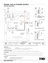
Main Circuit Board
Resettable Power - 24 VDC filtered,
power-limited, Class 2 (0.500 amps
maximum) to smoke detectors (IDC).
Supervise with a power supervision
relay EOLR-1
Nonresettable or Resettable Power
Jumper selectable by JP31, 24 VDC filtered,
power-limited, Class 2 (0.500 amps maximum)
. NonresettablePower suitable for
powering annunciators, Resettable
Power suitable for powering smoke detectors.
Supervise with a power supervision relay
EOLR-1
Configure TB9, Terminals 1 & 2
as Resettable or Nonresettable Power.
• Resettable Power - jumper JP31 pins 2 & 3.
• Nonresettable Power - jumper JP31
pins 1 & 2 (as shown).
Special Application Power
In this example NAC Output Circuits #1, #3 & #4, Style Y (Class B) (Supervised, Power Limited - Class 2)
NAC Output Circuit #2 (Releasing) is Style Y (Class B) (Supervised, NonPower-Limited, Class 1)
3.0 amps max. per circuit. (See Style Z illustrated near right edge of board).
4.7K , ½ watt End-of-Line Resistor PN 71252
Ω
Nonsupervised relay contacts
Contact Ratings:
2.0 amps @ 30 VDC (resistive)
0.5 amps @ 30 VAC (resistive)
Contacts shown below in normal
condition (AC power with no alarm,
trouble or supervisory activity).
A Fail Safe Trouble
relay switches to the
NC position during
trouble conditions and
under loss of all power.
Special Application
DC Power Outputs (24 VDC)
Nonsupervised, power-limited circuits (Class 2)
Supervise with a power supervision relay EOLR-1
Battery
Basic System Connections
Output Circuits - TB5 & TB7
3 Programmable Relays
Alarm* Trouble*
Supervisory*
NO NC C
24 VDC, supervised,
nonpower-limited
26 Amp Hour maximum
NO NC CNO NC C NO NC C
(* )Factory default relay programming
Power Supply Connector J15
Output
Circuit #1
NAC
+
+
+
4
3
J12
BATTERY
- +
TB5
TB4
TB7
TB6
TB8
TB9
J2
J7
J15
J3
JP24
JP31
JP30
J5
J4
J6
TB3
GND PWR
ANN-BUS
A B
RST AUX
PWR
RST/NONRST
AUXPWR
OUT1 OUT2
OUT3 OUT4
4XTMF OPT BD
Cut this jumper to supervise
the 4XTMF module when
installed (see J4 & J5)
Cut this jumper to
enable Supervisory
relay when 4XTMF
module is installed
2
1
JP43
CAC5 Class A Converter Module
-
+
+
-
3
2
1
B
+
B
-
11
B
+
B
-
22
+
+
+
B
+
B
-
33
B
+
B
-
11
B
+
B
-
66
IDCs 1 through 6, Style B (Class B) (Supervised, Power Limited, Class 2)
(See Style D illustrated near right edge of board).
4.7K , ½ watt End-of-Line Resistor PN 71252
Ω
Input Initiating Device Circuit - TB4 & TB6
Remove jumper JP43
to disable Ground Fault
Detection circuit (only
with approval of AHJ).
+
+
+
TB5/
TB7
TB4/
TB6
OUT1/3 OUT2/4
A
+
A
-
11 2
A
+
A
-
11
OUT OUT
TB2
TB1
J2
CAC5
Class A Converter Module
Dummy load all unused circuits with
4.7K , ½ watt End-of-Line resistors
Ω
Style Z (Class A) NAC
Style D (Class A) IDC
+ - + -
+ - + -
+ - + - + - + - + -
Important!
Removing Ground Fault
DisableJumper JP43 voids UL/NFPA
Style/Class identifications for circuits.
Remove jumper JP43 only with the
approval of the AHJ
(Authority Having Jurisdiction).
- +
- +
+ -
FIRE ALARM
AC POWER
TROUBLE
1
4
7
*
2
3
1
5
6
89
0
#
ABC
DEF
GHI
JKL
PRS TUV
QZ_
_/.
CLEAR
ESC
MODE
ST
ENTER
ALARM
DRILL
RESET
Output
Circuit #2
Releasing
Releasing Circuit
(Supervised, Power-Limited, Class 2)
REL-4.7K
TB5
OUT1 OUT2
+ - + -
B
+
B
-
22
Unused
Output Circuit
4.7K dummy load
P/N 71245
Ω
B
+
5
B
-
5
Output
Circuit #3
NAC
Output
Circuit #4
Input IDC
Circuit #1
Input IDC
Supervisory
Circuit #5
Input IDC
Water flow
Circuit #6
smoke
detector
polarized
bell
polarized
horn
polarized
strobe
heat
detector
pull
station
Normally
Open
Tam pe r
or
Pressure
Switches
Normally
Open
Waterflow
Devices
or
Pressure
Switches
B
+
B
-
33
manual
release
A
+
A
-
11
A
+
A
-
11

Product Features Product Description
MRP-2001 & MRP-2001E PN 53040:A 4/16/2007 11
SECTION 1 Product Description
The MRP-2001 is a six zone FACP for single and dual hazard deluge and preaction applications.
The FACP provides reliable fire detection, signaling and protection for commercial, industrial and
institutional buildings requiring water-based releasing. The FACP is compatible with System
Sensor’s i
3
detectors which are conventional smoke detectors that can transmit a maintenance
trouble signal to the FACP indicating the need for cleaning and a supervisory ‘freeze’ signal when
the ambient temperature falls below the detector rating of approximately 45
o
F (refer to System
Sensor for i
3
Installation and Maintenance Instructions). In addition, the control panel is
compatible with conventional input devices such as two-wire smoke detectors, four-wire smoke
detectors, pull stations, waterflow devices, tamper switches and other normally-open contact
devices. Refer to Device Compatibility Document for a complete listing of compatible devices.
Four outputs are programmable as NACs (Notification Appliance Circuits) or releasing solenoids.
Three programmable Form-C relays (factory programmed for Alarm, Trouble and Supervisory)
and 24 VDC special application resettable and nonresettable power outputs are also included on the
main circuit board. The FACP supervises all wiring, AC voltage, battery charger and battery level.
Activation of a compatible smoke detector or any normally-open fire alarm initiating device will
activate audible and visual signaling devices, illuminate an indicator, display alarm information on
the panel’s LCD, sound the piezo sounder at the FACP, activate the FACP alarm relay and operate
an optional module used to notify a remote station or initiate an auxiliary control function.
The MRP-2001E offers the same features as the MRP-2001 but allows connection to 220/240 VAC.
Unless otherwise specified, the information in this manual applies to both the 110/120 VAC and
220/240 VAC versions of the panels.
1.1 Product Features
• Six programmable Style B (Class B) IDCs (Initiating
Device Circuit)
• Four programmable Style Y (Class B) output circuits
- (special application power)
• Three programmable Form-C relays
• 7.0 amps total 24 VDC output current
• Resettable and non-resettable output power
• Built-in Programmer
• ANN-BUS for connection to optional:
ANN-80 Remote LCD Annunciator
ANN-I/O LED Driver
ANN-S/PG Printer Module
ANN-RLY Relay Module
ANN-LED Annunciator Module
• 80-character LCD display (backlit)
• Real-time clock/calendar with daylight savings time control
• History log with 256 event storage

Product Description Product Features
12 MRP-2001 & MRP-2001E PN 53040:A 4/16/2007
• Control Buttons
ACK (Acknowledge)
Alarm Silence
System Reset/Lamp Test
Drill
• Indicators
Fire Alarm
Supervisory
Trouble
AC Power
Alarm Silence
Discharge
• Piezo sounder for alarm, trouble and supervisory
• 24 volt operation
• Low AC voltage sense
• Outputs Programmable for:
Releasing Solenoids
NACs programmable for:
Silence Inhibit
Auto-Silence
Strobe Synchronization (System Sensor, Wheelock, Gentex, Faraday, Amseco)
Selective Silence (horn-strobe mute)
Temporal or Steady Signal
Silenceable or Nonsilenceable
Release Stage Sounder
• Designed for sprinkler standards NFPA 13, 15 and 16
• Disable/Enable control per input zone and output zone
• Extensive transient protection
• Dual hazard operation
• Adjustable waterflow discharge timer and two soak timers
• Cross-zone (double-interlock) capability
• Pre-programmed and custom application templates
• Automatic battery charger with charger supervision
• Silent or audible walktest capabilities
• Optional Dress Panel DP-51050 (red)
• Optional Trim Ring TR-CE (red) for semi-flush mounting the cabinet
• Optional CAC-5X Class A Converter Module for Outputs and IDCs
• Optional 4XTMF Municipal Box Transmitter Module
• Optional Digital Alarm Communicators (411, 411UD, 411UDAC)

Specifications Product Description
MRP-2001 & MRP-2001E PN 53040:A 4/16/2007 13
1.2 Specifications
AC Power
MRP-2001: 120 VAC, 60 Hz, 3.66 amps
MRP-2001E: 240 VAC, 50 Hz, 2.085 amps
Wire size: minimum #14 AWG (2.0 mm
2
) with 600V insulation
Supervised, nonpower-limited
Battery (sealed lead acid only) - J12
Maximum Charging Circuit - Normal Flat Charge: 27.6 VDC @ 1.4 amp
Supervised, nonpower-limited
Maximum Charger Capacity: 26 Amp Hour battery (two 18 Amp Hour batteries can be housed
in the FACP cabinet. Larger batteries require separate battery box such as the BB-26 or BB-55)
Minimum Battery Size: 7 Amp Hour
Initiating Device Circuits - TB4 and TB6
Alarm Zones 1 - 5 on TB 4
Alarm Zone 6 on TB6
Supervised and power-limited circuitry
Operation: All zones Style B (Class B)
Normal Operating Voltage: Nominal 20 VDC
Alarm Current: 15 mA minimum
Short Circuit Current: 40 mA max.
Maximum Loop Resistance: 100 ohms
End-of-Line Resistor: 4.7KΩ, 1/2 watt (Part #71252)
Standby Current: 2 mA
Refer to the Device Compatibility Document for listed compatible devices
Notification Appliance and Releasing Circuit(s) - TB5 and TB7
1
Four Output Circuits
Operation: Style Y (Class B)
Special Application power
Supervised and power-limited circuitry
Normal Operating Voltage: Nominal 24 VDC
Maximum Signaling Current: 7.0 amps (3.0 amps maximum per NAC)
End-of-Line Resistor: 4.7KΩ, 1/2 watt (Part #71252)
Max. Wiring Voltage Drop: 1.5 VDC
Refer to the Device Compatibility Document for compatible listed devices
Form-C Relays - Programmable - TB8
Relay 1 (factory default programmed as Alarm Relay)
Relay 2 (factory default programmed as fail-safe Trouble Relay)
Relay 3 (factory default programmed as Supervisory Relay)
Relay Contact Ratings: 2 amps @ 30 VDC (resistive) and 0.5 amps @ 30 VAC (resistive)
Auxiliary Trouble Input
The Auxiliary Trouble Input is an open collector, unsupervised circuit which can be used to
monitor external devices for trouble conditions. It can be connected to the trouble bus of a
peripheral, such as a power supply, which is compatible with open collector circuits.
All connections must be in conduit, less than 20 ft. (610 cm) in length in the same room.
Special Application Resettable Power - TB9
Operating Voltage: Nominal 24 VDC
Maximum Available Current: 500 mA - appropriate for powering 4-wire smoke detectors (see
note 1)
Power-limited Circuitry
Refer to the Device Compatibility Document for compatible listed devices
1. Total current for resettable power, nonresettable power and Output Circuits must not exceed
7.0 amps.

Product Description Controls and Indicators
14 MRP-2001 & MRP-2001E PN 53040:A 4/16/2007
Special Application Resettable or Nonresettable Power - TB9
Operating Voltage: Nominal 24 VDC
Maximum Available Current: 500 mA (see note 1)
Power-limited Circuitry
Jumper selectable by JP31 for resettable or nonresettable power:
Jumper pins 1 & 2 on JP31 for nonresettable power
Jumper pins 2 & 3 on JP31 for resettable power
Refer to the Device Compatibility Document for compatible listed devices
1.3 Controls and Indicators
LCD Display
The FACP uses an 80-character
(4 lines X 20 characters) high viewing angle
LCD display. The display includes a long life
LED backlight that remains illuminated. If AC
power is lost and the system is not in alarm, the
LED backlight will turn off to conserve batteries.
Key Panel
Mounted on the main circuit board, the key panel includes a window for the LCD display and
indicators as listed above. The key panel, which is visible with the cabinet door closed, has 25
keys, including a 16 key alpha-numeric pad similar to a telephone keypad.
Function keys:
• Acknowledge/Step
• Alarm Silence
• Drill
• System Reset (lamp test)
Service/program keys:
• Keys labeled 1 to 9
• * key
• # key
• 0 (recall) key
• 1st Event key
• Clear key
• Escape key
• Mode key
• Four cursor keys (up, down, left and right)
• Enter key
SYSTEM ALL NORMAL
10:00A 012106
Figure 1.1 Membrane/Display Panel
MRP2001kypd.cdr

Components Product Description
MRP-2001 & MRP-2001E PN 53040:A 4/16/2007 15
Local Piezo Sounder
A piezo sounder provides separate and distinct pulse rates for alarm, trouble and supervisory
conditions.
Indicators
Indicators are provided to annunciate the following conditions:
• Fire Alarm - red indicator
• Supervisory - yellow indicator
• AC Power - green indicator
• System Trouble - yellow indicator
• Alarm Silence - yellow indicator
• Discharge - red indicator
Local Piezo Sounder
A piezo sounder provides separate and distinct sounds for alarm, trouble, maintenance and
supervisory conditions as follows:
• Alarm - on steady
• Trouble - pulse 1 second on and 1 second off
• Maintenance - pulse ½ second on and ½ second off
• Supervisory - pulse ½ second on and ½ second off
1.4 Components
Main Circuit Board
The main circuit board contains the system’s CPU and other primary components and wiring
interface connectors. Optional modules plug in and are mounted to the main circuit board.
Power Supply
One FLPS-7 power supply is provided standard with each FACP, mounted to a chassis.
Cabinet
The backbox measures 16.65” (42.29 cm) x 19.0” (48.26 cm) x 5.207” (13.23 cm) and provides
space for two batteries (up to 18 Amp Hours). Also available is an optional dress panel (DP-51050
[red] and supplied standard with Canadian versions only, DP-51050LED for mounting ANN-LED
annunciator modules) which mounts inside the cabinet and trim-ring (TR-CE [red]).
Batteries
The cabinet provides space for two 18 Amp Hour batteries (larger batteries require use of a UL
listed battery box such as the BB-26 or BB-55). Batteries must be ordered separately.

Product Description Optional Modules and Accessories
16 MRP-2001 & MRP-2001E PN 53040:A 4/16/2007
1.5 Optional Modules and Accessories
CAC-5X Class A Converter Module
The CAC-5X Module can be used to convert the Style B (Class B) Initiating Device Circuits to
Style D (Class A) and Style Y (Class B) Output Circuits to Style Z (Class A). The modules connect
to J2 and J7 on the FACP main circuit board. Note that two Class A Converter modules are required
to convert all six Output Circuits and four Initiating Device Circuits.
4XTMF Transmitter Module
The 4XTMF provides a supervised output for local energy municipal box transmitter and alarm and
trouble reverse polarity. It includes a disable switch and disable trouble LED. A module jumper
option allows the reverse polarity circuit to open with a system trouble condition if no alarm
condition exists. The 4XTMF mounts to the main circuit board connectors J4 & J5.
ANN-80 LCD Annunciator
The ANN-80 is a remote LCD annunciator that mimics the information displayed on the FACP
LCD display.
ANN-LED Annunciator Module
The ANN-LED Annunciator Module provides three LEDs for each zone: Alarm, Trouble and
Supervisory.
ANN-RLY Relay Module
The ANN-RLY Module, which can be mounted inside the cabinet, provides 10 Form-C relays.
ANN-S/PG Serial/Parallel Printer Gateway
The ANN-S/PG
module provides a connection for a serial or parallel printer.
ANN-I/O LED Driver Module
The ANN-I/O module provides connections to a user supplied graphic annunciator.
Dress Panel
A dress panel DP-51050 (red) is available as an option. The dress panel restricts access to the
system wiring while allowing access to the membrane switch panel.
DP-51050LED Dress Panel
A DP-51050LED dress panel is provided standard only with Canadian versions of the FACP. The
dress panel restricts access to the system wiring while allowing access to the membrane switch
panel. It also allows the installation of an optional ANN-LED annunciator module.
TR-CE Trim-ring
A trim-ring TR-CE (red) is available as an option. The trim-ring allows semi-flush mounting of the
cabinet.
Battery Box
The BB-26 or BB-55 battery box may be used to house two batteries greater than 18 Amp Hour.
The battery box mounts directly below the control panel cabinet, centered to the main circuit board.

Backbox Mounting Installation
MRP-2001 & MRP-2001E PN 53040:A 4/16/2007 17
SECTION 2 Installation
The cabinet can be surface mounted or semi-flush mounted. The door is removable during the
installation period by opening and lifting it off the hinges. The cabinet mounts using two key slots
at the top of the backbox and two additional securing holes located at the bottom.
Carefully unpack the system and check for shipping damage. Mount the cabinet in a clean, dry,
vibration-free area where extreme temperatures or levels of humidity are not encountered. The area
should be readily accessible with sufficient room to easily install and maintain the panel. Locate
the top of the cabinet approximately 5 feet (1.5 m) above the floor with the hinge mounting on the
left. Determine the number of conductors required for the devices to be installed. Sufficient
knockouts are provided for wiring convenience. Select the appropriate knockout(s) and pull the
conductors into the box. All wiring should be in accordance with the National and/or Local codes
for fire alarm systems.
2.1 Backbox Mounting
The circuit board contains static-sensitive components. Always ground yourself with a proper wrist
strap before handling any boards so that static charges are removed from the body. Use static
suppressive packaging to protect electronic assemblies.
To prevent damage to the circuit board and to facilitate backbox mounting, the chassis with main
circuit board and transformer can be easily removed. Loosen the two 3/8” nuts securing the top
flanges of the chassis, then slide the chassis up to free it from the lower tabs. Place the chassis
assembly in a protective antistatic bag in a safe location until it can be reinstalled in the backbox.
Mark and predrill hole in the wall for the center top keyhole mounting bolt using the
dimensions illustrated in Figure 2.2 on page 18
Install center top fastener in the wall with the screw head protruding
Place backbox over the top screw, level and secure
Mark and drill the left and right upper and lower mounting holes
Note: outer holes (closest to sidewall) are used for 16” on-center stud mounting
Install remaining fasteners and tighten
!
See Page
mounting studs
mounting slots
mounting tabs
mounting holes
grounding stud:
attach solid earth
ground wire (refer to
Figure 2.4 on page 20)
Board on Chassis
Backbox
Figure 2.1 Chassis Mounting in Backbox
5UDBRDINBOX.CDR
mounting slots

Installation Backbox Mounting
18 MRP-2001 & MRP-2001E PN 53040:A 4/16/2007
9050UDencl.cdr
Figure 2.2 Cabinet Dimensions
Hinge Slot for optional
Dress Panel
Semi-Flush
mounting hole
Mounting
slots for
optional
Trim Ring
Hinge Slot for
optional Dress Panel
Semi-Flush Mounting
Do not recess box more
than 3.875” into wall to
avoid covering venting
holes on top of box.

Backbox Mounting Installation
MRP-2001 & MRP-2001E PN 53040:A 4/16/2007 19
Figure 2.3 Backbox
9050udcab.cdr

Installation Operating Power
20 MRP-2001 & MRP-2001E PN 53040:A 4/16/2007
2.2 Operating Power
WARNING: Several different sources of power can be connected to this panel. Disconnect all
sources of power before servicing. The panel and associated equipment may be damaged by
removing and/or inserting cards, modules or interconnecting cables while this unit is energized.
Primary Power Source (AC) and Earth Ground Connections
AC power connections are made inside the control panel cabinet. The primary power source for the
panel is 120 VAC, 60 Hz, 3.66 amps for the MRP-2001 or 240 VAC, 50 HZ, 2.085 amps for the
MRP-2001E. Run a pair of wires (with ground conductor) from the protected premises main
breaker box to the AC terminal block TB1 on the main power supply. As per the National
Electrical Code, use 14 AWG (2.00 mm
2
, 1.6 mm O.D.) or heavier gauge wire with 600V
insulation. No other equipment may be connected to this circuit. In addition, this circuit must be
provided with overcurrent protection and may not contain any power disconnect devices. A
separate Earth Ground connection must be made to ensure proper panel operation and lightning and
transient protection. Connect the Earth Ground wire [minimum 14 AWG (2.00 mm
2
)] to the
grounding stud in the backbox. Do not use conduit for the Earth Ground connection since this does
not provide reliable protection.
Secondary Power Source (Batteries)
Observe polarity when connecting the battery. Connect the battery cable to J12 on the main circuit
board using the plug-in connector and cable provided. The battery charger is current-limited and
capable of charging sealed lead acid batteries. The charger shuts off when the system is in alarm.
WARNING: Battery contains sulfuric acid which can cause severe burns to the skin and eyes and
can destroy fabrics. If contact is made with sulfuric acid, immediately flush the skin or eyes with
water for 15 minutes and seek immediate medical attention.
!
Figure 2.4 Operating Power Connections
120 VAC Power
Hot (L1)
Ground
Neutral (L2)
Ground Wire
J12
Batteries
rp2001powr.cdr
+-
/