Page is loading ...

Fire Control Communicator
MS-5024/MS-5024E
PN: 50066:D2 ECN 02-606
D
Document #50066
12/03/02 Rev.

LimWarLg.p65 01/10/2000
An automatic fire alarm system–typically made up of smoke
detectors, heat detectors, manual pull stations, audible warn-
ing devices, and a fire alarm control with remote notification
capability–can provide early warning of a developing fire.
Such a system, however, does not assure protection against
property damage or loss of life resulting from a fire.
The Manufacturer recommends that smoke and/or heat detec-
tors be located throughout a protected premise following the
recommendations of the current edition of the National Fire
Protection Association Standard 72 (NFPA 72),
manufacturer's recommendations, State and local codes, and
the recommendations contained in the Guide for Proper Use
of System Smoke Detectors, which is made available at no
charge to all installing dealers. A study by the Federal Emer-
gency Management Agency (an agency of the United States
government) indicated that smoke detectors may not go off in
as many as 35% of all fires. While fire alarm systems are de-
signed to provide early warning against fire, they do not guar-
antee warning or protection against fire. A fire alarm system
may not provide timely or adequate warning, or simply may not
function, for a variety of reasons:
Smoke detectors may not sense fire where smoke cannot
reach the detectors such as in chimneys, in or behind walls, on
roofs, or on the other side of closed doors. Smoke detectors
also may not sense a fire on another level or floor of a build-
ing. A second-floor detector, for example, may not sense a
first-floor or basement fire.
Particles of combustion or "smoke" from a developing fire
may not reach the sensing chambers of smoke detectors be-
cause:
• Barriers such as closed or partially closed doors, walls, or
chimneys may inhibit particle or smoke flow.
• Smoke particles may become "cold," stratify, and not reach
the ceiling or upper walls where detectors are located.
• Smoke particles may be blown away from detectors by air
outlets.
• Smoke particles may be drawn into air returns before
reaching the detector.
The amount of "smoke" present may be insufficient to alarm
smoke detectors. Smoke detectors are designed to alarm at
various levels of smoke density. If such density levels are not
created by a developing fire at the location of detectors, the
detectors will not go into alarm.
Smoke detectors, even when working properly, have sensing
limitations. Detectors that have photoelectronic sensing
chambers tend to detect smoldering fires better than flaming
fires, which have little visible smoke. Detectors that have ion-
izing-type sensing chambers tend to detect fast-flaming fires
better than smoldering fires. Because fires develop in differ-
ent ways and are often unpredictable in their growth, neither
type of detector is necessarily best and a given type of detec-
tor may not provide adequate warning of a fire.
Smoke detectors cannot be expected to provide adequate
warning of fires caused by arson, children playing with
matches (especially in bedrooms), smoking in bed, and violent
explosions (caused by escaping gas, improper storage of
flammable materials, etc.).
Heat detectors do not sense particles of combustion and
alarm only when heat on their sensors increases at a prede-
termined rate or reaches a predetermined level. Rate-of-rise
heat detectors may be subject to reduced sensitivity over time.
For this reason, the rate-of-rise feature of each detector
should be tested at least once per year by a qualified fire pro-
tection specialist.
Heat detectors are designed to protect
property, not life.
IMPORTANT!
Smoke detectors must be installed in the
same room as the control panel and in rooms used by the sys-
tem for the connection of alarm transmission wiring, communi-
cations, signaling, and/or power.
If detectors are not so lo-
cated, a developing fire may damage the alarm system, crip-
pling its ability to report a fire.
Audible warning devices such as bells may not alert people
if these devices are located on the other side of closed or
partly open doors or are located on another floor of a building.
Any warning device may fail to alert people with a disability or
those who have recently consumed drugs, alcohol or medica-
tion. Please note that:
• Strobes can, under certain circumstances, cause seizures
in people with conditions such as epilepsy.
• Studies have shown that certain people, even when they
hear a fire alarm signal, do not respond or comprehend the
meaning of the signal. It is the property owner's responsibil-
ity to conduct fire drills and other training exercise to make
people aware of fire alarm signals and instruct them on the
proper reaction to alarm signals.
• In rare instances, the sounding of a warning device can
cause temporary or permanent hearing loss.
A fire alarm system will not operate without any electrical
power. If AC power fails, the system will operate from standby
batteries only for a specified time and only if the batteries
have been properly maintained and replaced regularly.
Equipment used in the system may not be technically com-
patible with the control. It is essential to use only equipment
listed for service with your control panel.
Telephone lines needed to transmit alarm signals from a
premise to a central monitoring station may be out of service
or temporarily disabled. For added protection against tele-
phone line failure, backup radio transmission systems are rec-
ommended.
The most common cause of fire alarm malfunction is inade-
quate maintenance. To keep the entire fire alarm system in
excellent working order, ongoing maintenance is required per
the manufacturer's recommendations, and UL and NFPA stan-
dards. At a minimum, the requirements of Chapter 7 of NFPA
72 shall be followed. Environments with large amounts of
dust, dirt or high air velocity require more frequent mainte-
nance. A maintenance agreement should be arranged
through the local manufacturer's representative. Maintenance
should be scheduled monthly or as required by National and/
or local fire codes and should be performed by authorized pro-
fessional fire alarm installers only. Adequate written records
of all inspections should be kept.
While a fire alarm system may lower insurance
rates, it is not a substitute for fire insurance!
Fire Alarm System Limitations

LimWarLg.p65 01/10/2000
WARNING -
Several different sources of power can be con-
nected to the fire alarm control panel.
Disconnect all sources
of power before servicing. Control unit and associated equip-
ment may be damaged by removing and/or inserting cards,
modules, or interconnecting cables while the unit is energized.
Do not attempt to install, service, or operate this unit until this
manual is read and understood.
CAUTION -
System Reacceptance Test after Software
Changes.
To ensure proper system operation, this product
must be tested in accordance with NFPA 72 Chapter 7 after
any programming operation or change in site-specific soft-
ware. Reacceptance testing is required after any change, ad-
dition or deletion of system components, or after any modifica-
tion, repair or adjustment to system hardware or wiring.
All components, circuits, system operations, or software func-
tions known to be affected by a change must be 100% tested.
In addition, to ensure that other operations are not inadvert-
ently affected, at least 10% of initiating devices that are not
directly affected by the change, up to a maximum of 50 de-
vices, must also be tested and proper system operation veri-
fied.
This system meets NFPA requirements for operation at
0-49° C/32-120° F
and at a relative humidity of 85% RH (non-
condensing) at 30°
C/86° F. However, the useful life of the
system's standby batteries and the electronic components
may be adversely affected by extreme temperature ranges
and humidity. Therefore, it is recommended that this system
and all peripherals be installed in an environment with a nomi-
nal room temperature of 15-27° C/60-80° F.
Verify that wire sizes are adequate for all initiating and
indicating device loops. Most devices cannot tolerate more
than a 10% I.R. drop from the specified device voltage.
Like all solid state electronic devices, this system may
operate erratically or can be damaged when subjected to light-
ning-induced transients. Although no system is completely
immune from lightning transients and interferences, proper
grounding will reduce susceptibility.
Overhead or outside
aerial wiring is not recommended, due to an increased sus-
ceptibility to nearby lightning strikes.
Consult with the Techni-
cal Services Department if any problems are anticipated or
encountered.
Disconnect AC power and batteries prior to removing or in-
serting circuit boards. Failure to do so can damage circuits.
Remove all electronic assemblies prior to any drilling, filing,
reaming, or punching of the enclosure. When possible, make
all cable entries from the sides or rear. Before making modifi-
cations, verify that they will not interfere with battery, trans-
former, and printed circuit board location.
Do not tighten screw terminals more than 9 in-lbs.
Over-tightening may damage threads, resulting in reduced
terminal contact pressure and difficulty with screw terminal
removal.
Though designed to last many years, system components
can fail at any time. This system contains static-sensitive
components. Always ground yourself with a proper wrist strap
before handling any circuits so that static charges are re-
moved from the body. Use static-suppressive packaging
to protect electronic assemblies removed from the unit.
Follow the instructions in the installation, operating, and
programming manuals. These instructions must be followed
to avoid damage to the control panel and associated
equipment. FACP operation and reliability depend upon
proper installation by authorized personnel.
Adherence to the following will aid in problem-free
installation with long-term reliability:
WARNING: This equipment generates, uses, and can
radiate radio frequency energy and if not installed and
used in accordance with the instruction manual, may
cause interference to radio communications. It has
been tested and found to comply with the limits for class
A computing device pursuant to Subpart B of Part 15 of
FCC Rules, which is designed to provide reasonable
protection against such interference when operated in a
commercial environment. Operation of this equipment in
a residential area is likely to cause interference, in which
case the user will be required to correct the interference
at his own expense.
Canadian Requirements
This digital apparatus does not exceed the Class A
limits for radiation noise emissions from digital
apparatus set out in the Radio Interference Regulations
of the Canadian Department of Communications.
Le present appareil numerique n'emet pas de bruits
radioelectriques depassant les limites applicables aux
appareils numeriques de la classe A prescrites dans le
Reglement sur le brouillage radioelectrique edicte par le
ministere des Communications du Canada.
FCC Warning
Installation Precautions

4
Document #50066 Rev.D2 12/03/02 P/N 50066:D2
Notes

Document 50066 Rev. D2 12/03/02 P/N: 50066:D2 5
CHAPTER 1: Product Description .........................................................................................................................11
1.1: Product Features..........................................................................................................................................11
FIGURE 1-1: DP-5024 ........................................................................................................................12
FIGURE 1-2: MS-5024 Control Panel................................................................................................. 12
1.2: Controls and Indicators ...............................................................................................................................13
1.2.1: Front Panel Switches ........................................................................................................................13
FIGURE 1-3: Controls and Indicators .................................................................................................13
1.2.2: Display and Indicators ......................................................................................................................13
1.2.3: Local Sounder ...................................................................................................................................13
1.3: Circuits ........................................................................................................................................................13
1.3.1: Input Circuits.....................................................................................................................................13
1.3.2: Output Circuits..................................................................................................................................13
1.3.3: Notification Appliance Circuits ........................................................................................................14
1.3.4: Relays................................................................................................................................................14
1.4: Digital Communicator.................................................................................................................................14
1.5: Components.................................................................................................................................................14
1.5.1: Main Circuit Board ...........................................................................................................................14
1.5.2: Cabinet ..............................................................................................................................................14
1.5.3: Transformer Assembly......................................................................................................................14
1.5.4: Batteries ............................................................................................................................................15
1.6: Optional Devices .........................................................................................................................................15
1.6.1: ADM-24 ............................................................................................................................................15
1.6.2: RZA-5F .............................................................................................................................................15
1.6.3: CAC-5F.............................................................................................................................................15
1.6.4: NACA-2F..........................................................................................................................................15
1.6.5: DP-5024 ............................................................................................................................................15
1.6.6: BB-17F..............................................................................................................................................16
1.7: Specifications ..............................................................................................................................................16
1.8: Telephone Requirements and Warnings ......................................................................................................17
1.8.1: Telephone Circuitry...........................................................................................................................17
1.8.2: Digital Communicator.......................................................................................................................17
1.8.3: Telephone Company Rights and Warnings .......................................................................................17
1.8.4: For Canadian Applications................................................................................................................18
CHAPTER 2: Installation......................................................................................................................................... 19
2.1: Mounting Options .......................................................................................................................................19
2.2: Backbox Mounting......................................................................................................................................19
FIGURE 2-1: Cabinet Dimensions and Knockout Locations..............................................................20
FIGURE 2-2: Backbox and Battery Box .............................................................................................21
2.3: Operating Power..........................................................................................................................................22
FIGURE 2-3: Operating Power Connections.......................................................................................22
2.4: Input Circuits...............................................................................................................................................23
FIGURE 2-4: Typical Initiating Device Circuit Connections .............................................................23
2.5: Output Circuits ............................................................................................................................................24
2.5.1: DC Power Output Connections.........................................................................................................24
FIGURE 2-5: Auxiliary Power Connections .......................................................................................24
2.5.2: Telephone Circuits ............................................................................................................................24
2.5.3: Notification Appliance Circuits (full-wave rectified) .......................................................................24
FIGURE 2-6: Typical NAC Connections ............................................................................................24
2.5.4: Programmable Relays .......................................................................................................................25
FIGURE 2-7: Programmable Relay Terminals....................................................................................25
2.6: UL Power-limited Wiring Requirements ....................................................................................................26
Table of Contents

Table of Contents
6
Document #50066 Rev. D2 12/03/02 P/N 50066:D2
FIGURE 2-8: Typical Wiring Diagram for UL Power-limited Requirements ....................................26
2.7: Digital Communicator.................................................................................................................................27
FIGURE 2-9: Wiring Phone Jacks.......................................................................................................27
2.8: Optional Boards...........................................................................................................................................28
2.8.1: ADM-24 Annunciator Driver Module ..............................................................................................28
FIGURE 2-10: ADM-24 ......................................................................................................................28
2.8.2: RZA-5F Remote Annunciator...........................................................................................................28
FIGURE 2-11: RZA-5F .......................................................................................................................28
FIGURE 2-12: Wiring the RZA-5F/ADM-24 .....................................................................................29
FIGURE 2-13: Installing Annunciator in Single-Gang Box................................................................29
2.8.3: NACA-2F and CAC-5F Class A Converter Modules.......................................................................30
FIGURE 2-14: NACA-2F Style Z Converter Module.........................................................................30
FIGURE 2-15: CAC-5F Style D Converter Module............................................................................30
CHAPTER 3: Programming Instructions...............................................................................................................31
3.1: Entering Program Mode ..............................................................................................................................31
3.2: Switch (Key) Functions...............................................................................................................................32
FIGURE 3-1: Control Panel Keypad ...................................................................................................32
3.3: Programming Options .................................................................................................................................32
TABLE 3-1: 3+1, 4+1 Express, 4+1 Standard and Expanded, 4+2 Expanded - Primary....................33
TABLE 3-2: 4+2 Standard and 4+2 Express Format - Primary..........................................................35
TABLE 3-3: 3+1, 4+1 Express, 4+1 Standard and Expanded, 4+2 Expanded - Secondary................37
TABLE 3-4: 4+2 Standard and 4+2 Express Format - Primary..........................................................39
FIGURE 3-2: Verification Timing Diagram........................................................................................40
TABLE 3-5: ........................................................................................................................................41
CHAPTER 4: Operating Instructions ....................................................................................................................46
4.1: Switches.......................................................................................................................................................46
4.1.1: Reset ..................................................................................................................................................46
4.1.2: Silence ...............................................................................................................................................46
4.1.3: Mode..................................................................................................................................................47
4.1.4: 1st Event............................................................................................................................................47
4.1.5: Down Arrow......................................................................................................................................47
4.1.6: Up Arrow...........................................................................................................................................47
4.1.7: [ENTER/STORE]..............................................................................................................................47
4.2: Display and LEDs........................................................................................................................................47
FIGURE 4-1: Phone Connectors and LEDs.........................................................................................48
4.3: Operation .....................................................................................................................................................49
4.3.1: Alarm Response ................................................................................................................................49
4.3.2: Alarm Restoral ..................................................................................................................................49
4.3.3: System Supervisory Condition Response .........................................................................................50
4.3.4: System Supervisory Restoral Response ............................................................................................50
4.3.5: Trouble Condition Response .............................................................................................................50
4.3.6: Trouble Conditions Restoral .............................................................................................................51
4.3.7: Off Normal Reporting .......................................................................................................................51
4.3.8: Zone Disable/Enable .........................................................................................................................51
4.3.9: Fire Drill............................................................................................................................................52
4.3.10: No Battery/Low Battery..................................................................................................................52
4.4: Central Station Communications.................................................................................................................52
TABLE 4-1: Format Selection Addresses (16 & 42)...........................................................................53
TABLE 4-2: Format Selection Address Explanation...........................................................................54
4.4.1: Transmittal Priorities.........................................................................................................................55
TABLE 4-3: Compatible UL Listed Receivers....................................................................................56


8
Document #50066 Rev.D2 12/03/02 P/N 50066:D2
Notes

This control panel has been designed to comply with standards set forth by the following regulatory agencies:
• Underwriters Laboratories Standard UL 864
• NFPA 72 National Fire Alarm Code for Local, Remote Station and Central Station Fire Alarm Systems
• CAN/ULC - S527M Standard for Control Units for Fire Alarm Systems
NFPA Standards
NFPA 72 National Fire Alarm Code for Central Station Signaling Systems Protected Premises Unit
(Automatic, Manual and Waterflow), Local Fire Alarm Systems and Remote Station Fire Alarm
Systems.
Underwriters Laboratories Documents:
UL 38 Manually Actuated Signaling Boxes
UL 217 Smoke Detectors, Single and Multiple Station
UL 228 Door Closers–Holders for Fire Protective Signaling Systems
UL 268 Smoke Detectors for Fire Protective Signaling Systems
UL 268A Smoke Detectors for Duct Applications
UL 346 Waterflow Indicators for Fire Protective Signaling Systems
UL 464 Audible Signaling Appliances
UL 521 Heat Detectors for Fire Protective Signaling Systems
UL 864 Standard for Control Units for Fire Protective Signaling Systems
UL 1481 Power Supplies for Fire Protective Signaling Systems
UL 1638 Visual Signaling Appliances
UL 1971 Signaling Devices for Hearing Impaired
CAN/ULC - S524M Standard for Installation of Fire Alarm Systems
Other:
NEC Article 250 Grounding
NEC Article 300 Wiring Methods
NEC Article 760 Fire Protective Signaling Systems
Applicable Local and State Building Codes
C22.1, Canadian Electrical Code, Part I
C22.2 No. 0, General Requirements - Canadian Electrical Code, Part II
C22.2 No. 0.4, Bonding and Grounding of Electrical Equipment (Protective Grounding) - Canadian
C282, Emergency Electrical Power Supply for Buildings - Canadian
Requirements of the Local Authority Having Jurisdiction (LAHJ)
Fire•Lite Documents
Fire•Lite Device Compatibility Document Document #15384
Before proceeding, the installer should be familiar with the following documents.
Document #50066 Rev. D2 12/03/02 P/N 50066:D2
9

10
Document #50066 Rev.D2 12/03/02 P/N 50066:D2
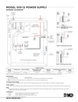
Note: When dressing wires, maintain a minimum of 0.25" distance between conductors to power-limited and
nonpower-limited circuits.
TB1
Secondary
Transformer
Connector

Document #50066 Rev. D2 12/03/02 P/N 50066:D2
11
Product Description
CHAPTER 1 Product Description
The MS-5024 is a combination control panel and digital communicator all on one circuit board. It is a five-zone
panel which uses conventional input devices. The panel accepts waterflow devices, two-wire smoke detectors, four-
wire smoke detectors, pull stations and other normally open contact devices. Outputs include two NACs (Notifica-
tion Appliance Circuits) and two programmable relays.
The integral communicator transmits system status (alarms, troubles, AC loss, etc.) to UL listed Central Stations via
the public switched telephone network. The control panel has a built-in programmer and may also serve as a slave
communicator to a host control panel. It also supervises all wiring, AC voltage, telephone line input voltage and
battery level.
The MS-5024E offers the same features as the MS-5024 but allows connection to 220/240 VAC input. Note that
unless otherwise specified, the term MS-5024 shall be used in this manual to refer to both the MS-5024 and
MS-5024E Fire Control Communicators.
1.1 Product Features
• Selectable as Fire Panel, Fire Panel/Communicator or Slave Communicator
• Programmable Zone ID:
✓ 2-wire smoke
✓ Pull station
✓ Normally open contact
✓ Supervisory
✓ Supervisory auto-resettable
✓ Waterflow silenceable
✓ Waterflow nonsilenceable
• One Style D (Class A) Initiating Zone
• Four Style B (Class B) Initiating Zones
• 3.6 amps usable power
• Two NFPA Style Y (Class B) Notification Appliance Circuits
• Built-in programmer
• Built-in voltmeter
• Telephone Line Active LED indicators
• Communication confirmation (Kissoff) LED
• Disable report by event
• Programmable Event Codes
• 24 volt operation
• Real-Time clock
• Trouble reminder
• Alarm verification
• Alarm presignal
• RZA-5F Remote Annunciator (requires ADM-24 Annunciator Driver Module)
• Small size - 14.5" (36.83 cm) X 12.5" (31.75 cm) X 2.875" (7.303 cm)
• History file with 32 event storage
• Silence inhibit per NAC

Product Features
12
Document #50066 Rev.D2 12/03/02 P/N 50066:D2
• Auto-silence per NAC
• Touchtone/rotary dialing
• Programmable make/break ratio
• Fuseless design
• Number of dial attempts (5 minimum, 10 maximum)
• Programmable channel ID (slave)
• Programmable zone delay (waterflow only)
• Two Form-C programmable relays
• Low AC voltage sense
•One-man Walktest
• Optional Dead Front cover (DP-5024)
• CAC-5F Class A Converter module for Initiating Device Circuits
• NACA-2F Class A Converter module for Notification Appliance Cir-
cuits
FIGURE 1-1:
DP-5024
B+ B- B+ B- B+ A+ A- B- B+ B- B+ B-
1234
1
1
2
2
34
TEST CONNECTOR
J1
J3
BELLS
1 2
TB5
TB4
TB3
TB2
TB1
NO NC C NO NC C
ZONE 1 ZONE 2
ZONE 4 ZONE 5
ZONE 3
PRIMARY SECONDARY
KISS OFF
/LO AD
LED 3
PRIMARY
ACTIVE
LED 1
SECONDARY
ACTIVE
LED 2
24V NON-
RESETTA BLE
24V
RESETTA BLE
FIGURE 1-2:
MS-5024 Control Panel
Notification
Appliance
Circuits
Programmable
Relays
5 Input
Zones
Annunciator
Driver Module
Interface
Connector
Primary &
Secondary
Phone Lines
Keypad
Holds up to 7 AH Batteries Up to 60 Hrs. of Standby
Piezo 85dB
Four
Character
7-Segment
LED Display

Document #50066 Rev. D2 12/03/02 P/N 50066:D2
13
Controls and Indicators
1.2 Controls and Indicators
1.2.1 Front Panel Switches
RESET Digits 0 - 9
SILENCE A
MODE B
Up Arrow C
Down Arrow D
1st EVENT E
ENTER/STORE F
1.2.2 Display and Indicators
• Four 7-Segment Displays - red
• Alarm - red LED
• Trouble - yellow LED
• Supervisory - yellow LED
• Silence - yellow LED
• AC Power - green LED
• Primary Phone Line Active - red LED
• Secondary Phone Line Active - red LED
• 'Kissoff' Signal from Central Station - green LED
1.2.3 Local Sounder
A piezo sounder provides separate and distinct sounds for alarm, trouble and supervisory conditions.
1.3 Circuits
1.3.1 Input Circuits
Five input circuits provide Style B configuration with one circuit also configurable for Style D. Input circuits may be
used as standard fire control panel zones or slave communicator input channels.
• Initiating Device Circuit 1 (Style B) accepts Normally Open contact devices and 2-wire smoke detectors
• Initiating Device Circuit 2 (Style B) accepts Normally Open contact devices and 2-wire smoke detectors
• Initiating Device Circuit 3 (Style B/D) accepts Normally Open contact devices, 2-wire smoke detectors and
waterflow devices
• Initiating Device Circuit 4 (Style B) accepts Normally Open contact devices and 2-wire smoke detectors
• Initiating Device Circuit 5 (Style B) accepts Normally Open contact devices and 2-wire smoke detectors
1.3.2 Output Circuits
• 24 Volt Resettable Power Output
• 24 Volt Nonresettable Power Output
• Primary Telephone Line
• Secondary Telephone Line
• 24 Volt Battery Charger
FIGURE 1-3:
Controls and Indicators

Digital Communicator
14
Document #50066 Rev.D2 12/03/02 P/N 50066:D2
1.3.3 Notification Appliance Circuits
Two NACs (Notification Appliance Circuits) configurable for Style Y (Class B) with various programmable features.
1.3.4 Relays
Two dry Form-C relay contacts programmable for Alarm, Trouble, Supervisory and/or Communications Failure.
Contacts are rated 2 amps @ 30 VDC (resistive) and 0.5 amps @ 30 VAC (resistive).
1.4 Digital Communicator
Two modular phone jacks allow easy connection to telephone lines. Modular jacks are labeled PH1 and PH2 for the
Primary and Secondary phone lines. Telephone line active red LEDs are provided as well as a green 'Kissoff” LED.
The integral digital communicator provides the following functions:
• Line Seizure - takes control of the phone lines, disconnecting any premises phones
• Off/On Hook - perform on and off-hook status to the phone lines
• Listen for dial tone - 440 hertz tone typical in most networks
• Dialing the Central Station(s) number - default is Touch-Tone
®
, programmable to rotary
• For tone burst or touchtone type formats: discern proper 'Ack' and 'Kissoff' tone(s) - the frequency and time
duration of the tone(s) vary with the transmission format. The control panel will adjust accordingly
• Communicate in the following formats:
✓
12 Tone Burst Types: 20 pps
(3+1, 4+1 and 4+2 Standard, 3+1 Expanded, 4+1 Expanded, 4+2 Expanded)
✓
2 Touchtone Types:
4+1 Ademco Express and 4+2 Ademco Express
Refer to Table 4-3, “Compatible UL Listed Receivers,” on page 56 for a list of compatible receivers.
1.5 Components
1.5.1 Main Circuit Board
The main circuit board contains the system’s CPU, power supply, other primary components and wiring interface
connectors. Optional modules plug in and are mounted to the main circuit board. The main circuit board is delivered
premounted in the cabinet.
1.5.2 Cabinet
The cabinet is red with an attractive navy blue front overlay. The backbox measures 14.5" (36.83 cm) X 12.5" (31.75
cm) X 2.875" (7.303 cm) and provides space for two batteries (up to 7 Amp Hour). Also available is an optional
dress panel (DP-5024), which mounts inside the cabinet.
1.5.3 Transformer Assembly
One 100 VA transformer is provided standard with the panel.

Document #50066 Rev. D2 12/03/02 P/N 50066:D2
15
Optional Devices
1.5.4 Batteries
The cabinet provides space for 7 Amp Hour batteries (for 12 Amp Hour to 18 Amp Hour batteries use the UL listed
BB-17F battery box). Batteries must be ordered separately.
1.6 Optional Devices
1.6.1 ADM-24
The ADM-24 Annunciator Driver Module supports the RZA-5F Remote Annunciator module. Annunciator wiring is
supervised for open circuits by this module. The Annunciator Driver Module mounts to connector J3 in the upper
right corner of the main board. Refer to Figure 1-2 on page 12 and Figure 2-10 on page 28.
1.6.2 RZA-5F
The RZA-5F Remote Annunciator mounts on a standard single-gang box and provides LED indications of the
following:
✓
Alarm Zone 1 (red LED)
✓
Alarm Zone 2 (red LED)
✓
Alarm Zone 3 (red LED)
✓
Alarm Zone 4 (red LED)
✓
Alarm Zone 5 (red LED)
✓
System Trouble (yellow LED)
A Local Trouble Sounder and Tone Silence Switch are also provided. All LEDs and their wiring are supervised for
open conditions. Any open condition will cause the System Trouble LED to illuminate. Slide in paper labels permit
an easy change of zone information (refer to Figure 2-11 on page 28). Note that the RZA-5F Remote Annunciator
requires the use of the ADM-24 Annunciator Driver Module. Only one ADM-24/RZA-5F combination is allowed per
system.
1.6.3 CAC-5F
The CAC-5F Class A Converter module converts the Style B (Class B) Initiating Device Circuits to Style D (Class
A). The CAC-5F mounts to terminal block TB2 located in the upper right corner of the main circuit board (refer to
Figure 1-2 on page 12 and Figure 2-15 on page 30). The removable terminal block on the CAC-5F module provides
for ease of wiring.
1.6.4 NACA-2F
The NACA-2F Notification Appliance Circuit Class A Converter module converts the two NAC circuits from Style
Y (Class B) to Style Z (Class A). The converter module mounts to terminal block TB5 located in the upper left cor-
ner of the main circuit board (refer to Figure 1-2 on page 12 and Figure 2-14 on page 30). The removable terminal
block on the NACA-2F module provides for ease of wiring.
1.6.5 DP-5024
The DP-5024 Dress Panel is red and is available as an option (required for Canadian installations). The dress panel
restricts access to the system wiring while allowing access to the membrane switch panel (refer to Figure 1-1 on page
12).

Specifications
16
Document #50066 Rev.D2 12/03/02 P/N 50066:D2
1.6.6 BB-17F
The BB-17F Battery Box may be used to house two 12 Amp Hour or 18 AMP Hour batteries. The battery box
mounts directly below the control panel cabinet (refer to Figure 2-2 on page 21). The BB-17F is red and is provided
with knockouts.
1.7 Specifications
AC Power - TB1
MS-5024: 120 VAC, 60 Hz, 1.2 amps
MS-5024E: 220/240 VAC, 50 Hz, 0.6 amps
Supervised for AC loss and brownout
Wire size: minimum 14 AWG (2.00 mm
2
) with 600V insulation
Battery (lead acid only) - J1
Maximum charging circuit: Normal Flat Charge - 27.6V @ 0.8 amp
Maximum charger capacity: 17 Amp Hour battery (MS-5024 cabinet holds maximum 7 Amp Hour battery. Larger
batteries require Fire•Lite BB-17F or other UL listed battery cabinet).
Supervised for low and no battery
Initiating Device Circuits - TB2
Detector zones 1, 2, 3, 4 and 5
Power-limited circuitry
Operation: All zones (NFPA Style B), Zone 3 (NFPA Style B or D). Use CAC-5F for Style D operation
Normal operating voltage: 24 VDC (ripple = 100mV maximum)
Alarm current: 26 mA Short circuit current: 42 mA maximum
Maximum loop resistance: 100 ohms
End-of-Line Resistor: 4.7K, ½ watt (P/N 27072 UL listed)
Detector loop current sufficient to ensure operation of one alarmed detector/zone
Standby current: 7.26 mA (includes ELR and 2 mA maximum detector current)
Smoke Detector Identifier A
Refer to Fire•Lite Device Compatibility Document for listed compatible devices
Notification Appliance Circuits - TB5
Nonregulated special purpose power, Style Y supported. Use NACA-2F for Style Z operation
Power-limited circuitry
Operating voltage nominal 24 volts
Current limit: PTC Maximum signaling current/circuit: 1.5 amps (3.0 amps max. for all external devices
End-of-Line Resistor: 4.7K, ½ watt (P/N 71252 UL listed) for Notification Appliance Circuits
Refer to Fire•Lite Device Compatibility Document for listed compatible devices
Programmable Relays - TB4
Contact rating: 2.0 amps @ 30 VDC (resistive), 0.5 amps @ 30 VAC (resistive)
Programmable: Form-C
Four-Wire Smoke Detector Power - TB4, Terminals 3(+) & 4(-)
Maximum ripple voltage: 10 mV
RMS
Operating voltage: nominal 24 volts
Up to 300 mA is available for powering 4-wire smoke detectors
Power-limited circuitry Maximum standby current: 50 mA
Refer to Fire•Lite Device Compatibility Document for compatible listed devices

Document #50066 Rev. D2 12/03/02 P/N 50066:D2
17
Telephone Requirements and Warnings
Nonresettable 24 VDC Power - TB4, Terminals 1(+) & 2(-)
Maximum ripple voltage: 10 mV
RMS
Operating voltage: nominal 24 volts
Total DC current available from this output is up to 300 mA
Power-limited circuitry Maximum standby current is 150 mA
Refer to Fire•Lite Device Compatibility Document for compatible listed devices
Notes:
1.
For power supply calculations, refer to “Battery Calculations” on page 63
2.
Total current for nonresettable power, 4-wire smoke power and two NACs must not exceed 3.6 amps
1.8 Telephone Requirements and Warnings
1.8.1 Telephone Circuitry
Ringer Equivalence Number (REN) = 1.3B
AC Impedance 10.0 Mega Ohm
Complies with FCC Part 68
Mates with RJ31X Male Connector
Supervision Threshold: less than 4.0 volts for 2 minutes
The REN is used to determine the quantity of devices which may be connected to the telephone line. Excessive
RENs on the telephone line may result in the devices not ringing in response to an incoming call. In most, but not all
areas, the sum of the RENs should not exceed five (5.0). To be certain of the number of devices that may be con-
nected to the line, as determined by the total RENs, contact the telephone company to determine the maximum REN
for the calling area.
1.8.2 Digital Communicator
Before connecting the control panel to the public switched telephone network, the installation of two RJ31X jacks is
necessary. The following information is provided if required by the local telephone company:
Manufacturer: Fire•Lite Alarms, Inc.
One Fire-Lite Place
Northford, CT 06472
Product Model Number: MS-5024
FCC Registration Number: 1W6USA-20004-AL-E
Ringer Equivalence: 1.3B
Note: The FCC ID label is located on the inside of the control panel door.
1.8.3 Telephone Company Rights and Warnings
The telephone company under certain circumstances may temporarily discontinue services and/or make changes in
its facilities, services, equipment or procedures which may affect the operation of this control panel. However, the
telephone company is required to give advance notice of such changes or interruptions.
If the control panel causes harm to the telephone network, the telephone company reserves the right to temporarily
discontinue service. Advance notification will be provided except in cases when advance notice is not practical. In
such cases, notification will be provided as soon as possible. The opportunity will be given to correct any problems
and to file a complaint.
DO NOT CONNECT THIS PRODUCT TO COIN TELEPHONE, GROUND START OR PARTY LINE SERVICES.

Telephone Requirements and Warnings
18
Document #50066 Rev.D2 12/03/02 P/N 50066:D2
When the control panel activates, premises phones will be disconnected.
Two separate phone lines are required. Do not connect both telephone interfaces to the same telephone line.
The control panel must be connected to the public switched telephone network upstream of any private telephone
system at the protected premises.
An FCC compliant telephone cord must be used with this equipment. This equipment is designed to be connected to
the telephone network or premises wiring using a compatible RJ31X male modular plug which is Part 68 compliant.
1.8.4 For Canadian Applications
The following is excerpted from CP-01 Issue 5:
“NOTICE: The Industry Canada (IC) label identifies certified equipment. This certification means that the equip-
ment meets certain telecommunications network protective, operational and safety requirements as prescribed in the
appropriate Terminal Equipment Technical Requirements document(s). The Department does not guarantee the
equipment will operate to the user’s satisfaction.”
Before installing this equipment, users should ensure that it is permissible to be connected to the facilities of the local
telecommunications company. The equipment must also be installed using an acceptable method of connection. The
customer should be aware that compliance with the above conditions may not prevent degradation of service in some
situations.
Repairs to certified equipment should be made by an authorized Canadian maintenance facility designated by the
supplier. Any repairs or alterations made by the user to this equipment, or equipment malfunctions, may give the
telecommunications company cause to request the user to disconnect the equipment.
Users should ensure for their own protection that the electrical ground connections of the power utility, telephone
lines and internal metallic water pipe system, if present, are connected together. This precaution may be particularly
important in rural areas.
CAUTION
Users should not attempt to make such connections themselves, but should contact the appropriate electric inspection
authority or electrician.
“The Ringer Equivalence Number
(REN) assigned to each terminal device provides an indication of the maximum
number of terminals allowed to be connected to a telephone interface. The termination of an interface may consist of
any combination of devices subject only to the requirement that the sum of the REN of all devices does not exceed 5.”
Representative: NOTIFIER, CANADA
24 Viceroy Road
Concord, Ontario L4K2L9
IC Certificate Number: 21325785A
Ringer Equivalence Number (REN): 1.3B
Load Number: 2

Document #50066 Rev. D2 12/03/02 P/N 50066:D2
19
Installation
CHAPTER 2 Installation
2.1 Mounting Options
The cabinet may be either semi-flush or surface mounted. The
door is removable during the installation period by opening
and lifting off the hinges. The cabinet mounts using two key
slots and two additional 0.250" diameter holes located in the
backbox. The key slots are located at the top of the backbox
and the two securing holes at the bottom.
Carefully unpack the system and check for shipping damage.
Mount the cabinet in a clean, dry, vibration-free area where
extreme temperatures are not encountered. The area should be
readily accessible with sufficient room to easily install and
maintain the panel. Locate the top of the cabinet approxi-
mately five feet above the floor with the hinge mounting on
the left. Determine the number of conductors required for the
devices to be installed. Sufficient knockouts are provided for
wiring convenience. Select the appropriate knockout(s) and
pull the required conductors into the box. Note that there are
no knockouts located on the left (hinged) side of the cabinet.
All wiring should be in accordance with the National and/or
Local codes for fire alarm systems.
2.2 Backbox Mounting
• Refer to Figure 2-1 on page 20 and Figure 2-2 on page 21
• Make certain there is no power (AC or DC) applied to the control panel
• Open the door and lift the door off the pin hinges
• Remove AC wiring
• Remove the main PC board assembly by unscrewing the five screws in the corners of the board. Two stand-
offs support the board in the center. Set the board aside in a safe, clean place. Avoid static discharge which
may damage the board
• Mark and predrill holes for the top two keyhole mounting bolts using the dimensions shown
• Install two upper fasteners in the wall with the screw heads protruding
• Using the upper 'keyholes', mount the backbox over the two screws
• Mark and drill the lower two holes
• Mount backbox, install remaining fasteners and tighten
• When the location is dry and free of construction dust, reinstall the main PC board

Backbox Mounting
20
Document #50066 Rev.D2 12/03/02 P/N 50066:D2
Draw wires through the respective knockout locations.
12.625"
(32.068 cm)
14.625“ (37.148 cm)
16.625" (42.228 cm)
17.625"
(44.768 cm)
3.000“
(
7.620 cm
)
3.000“
(
7.620 cm
)
1.250“ (3.175 cm)
10.000“ (25.400 cm)
1.250“
(3.175 cm)
1.25“
(3.175 cm)
1.25“
(3.175 cm)
1.125“
(2.858 cm)
0.875“
(2.223 cm)
14.5“
(36.83 cm)
3.25“
(8.255 cm)
1.75“
(
4.445 cm
)
3.5“
(8.89 cm)
12.5“ (31.75 cm)
4.125“ (10.478 cm)
6.125“ (15.558 cm)
8.125“ (20.638 cm)
10.125“
(
25.718 cm
)
1.000“ (2.540 cm)
6.5“ (16.51 cm)
9.500“ (24.130 cm)
(7.62 cm)
3.0“
FIGURE 2-1:
Cabinet Dimensions and Knockout Locations
Right Side
Top
Bottom
TR-3-R Trim Ring
/