Page is loading ...

WIDE
(
-
)
TELE
(+)
MENU
VIDEO OUT
CONTROL
POWER IN
Class 2 Only
+ DC 12V
-
BLC
(SET)
WIDE
(
-
)
MENU
S-VIDEO OUT
VIDEO OUT
CONTROL
POWER IN
Class 2 Only
TELE
(+)
BLC
(SET)
R T
TELE
(
+
)
BLC
(
SET
)
WIDE
(
-
)
MENU
VIDEO OUT
CABLE
DISTANCE
2 3
AC 24V
/
DC 12V
Class 2 Only
1
RS422
TELE
(
+
)
BLC
(
SET
)
WIDE
(
-
)
MENU
VIDEO OUT
VIDEO
OUT
UTP
OUT
AC 24V
/
DC 12V
Class 2 Only
RS485 UTP OUT
Digital Zoom Camera Series
Thank you for purchasing this COLOR ZOOM CAMERA.
Model Description
Safety and Precautions
Features
Control Names and Locations
Control Function
Installation
Connection Diagram
Remote Controller Operation
Communication Protocol
On-Screen Display
Menu Format
Menu Format Table
Specifications
1.
2.
3.
4.
5.
6.
7.
8.
9.
10.
11.
12.
13.
5
6
7
8
12
13
20
21
23
24
26
27
28
CAUTION!
TO REDUCE THE RISK OF ELECTRIC SHOCK,
DO NOT REMOVE COVER (OR BACK).
NO USER-SERVICEABLE PARTS INSIDE.
REFER SERVICING TO QUALIFIED
SERVICE PERSONNEL.
CAUTION
RISK OF ELECTRIC SHOCK
DO NOT OPEN
Explanation of two Symbols
The lightning flash with arrowhead symbol,
within an equilateral triangle, is intended to
alert the user to the presence of un-insulated
"dangerous voltage" within the product's
The exclamation point within an equilateral
triangle is intended to alert the user to the
presence of important operating and
maintenance-(servicing) instructions in the
THE GRAPHIC SYMBOLS WITH SUPPLEMENTAL MARKING ARE
ON THE BOTTOM OF THE SYSTEM.
"WARNING-TO PREVENT FIRE OR SHOCK HAZARD, DO NOT
EXPOSE THE UNIT TO RAIN OR MOISTURE"
enclosure that may be of sufficient magnitude to constitute a
risk of electric shock to persons.
literature accompanying the appliance.
3
COLOR VIDEO CAMERA
2
Digital Power Zoom
5
COLOR VIDEO CAMERA
4
Digital Power Zoom
7
COLOR VIDEO CAMERA
6
Digital Power Zoom
11
COLOR VIDEO CAMERA
10
Digital Power Zoom
13
COLOR VIDEO CAMERA
12
Digital Power Zoom
15
COLOR VIDEO CAMERA
14
Digital Power Zoom
19
COLOR VIDEO CAMERA
18
Digital Power Zoom
21
COLOR VIDEO CAMERA
20
Digital Power Zoom
23
COLOR VIDEO CAMERA
22
Digital Power Zoom
9
COLOR VIDEO CAMERA
8
Digital Power Zoom
17
COLOR VIDEO CAMERA
16
Digital Power Zoom
27
COLOR VIDEO CAMERA
26
Digital Power Zoom
25
COLOR VIDEO CAMERA
24
Digital Power Zoom
31
COLOR VIDEO CAMERA
30
Digital Power Zoom
29
COLOR VIDEO CAMERA
28
Digital Power Zoom
Avoid using the camera in extreme temperature environments.
Using the camera in temperatures exceeding 50 C or below -10C may
lessen picture quality or cause the camera to malfunction.
Avoid using the camera in high humidity environments.
Using the camera in places with high humidity may lessen picture quality
because of moisture on the lens.
Avoid using the camera in unsteady lighting.
The camera will not work properly in places with great changes in
illumination intensity, such as fluorescent lamps.
Make sure no foreign substances get on the front glass of the camera.
Do not disassemble the camera and prevent foreign substances
from getting into the camera.
Make sure that the camera is not exposed to an intense light
source such as direct sunlight.
It may damage the CCD.
Camera may be damaged if dropped or subjected to strong impact.
Keep camera dry.
The camera will be damaged if immersed in water.
Avoid using the camera in the presence of oil and gas.
The camera will be damaged if oil or gas penetrates the exterior.
Caution
- Smear or blooming (when bright areas spreads out) may occur when
photographing in strong light, i.e. car headlights, etc.
- Make sure that you are using a compatible power adapter before
connecting it to the camera.
/
TELE / WIDE
MENU
Move up and down
using the TELE/
WIDE button.
1 BACKLIGHT
2 NEG / POS
3 COLOR
4 WB CONTROL
5 SHUTTER
6 CAMERA
OFF
POS
ON
AUTO
1/10000
123
MENU
Can be changed
using the /
button.
1). General Model
NO
NAME FUNCTION
1 BACKLIGHT
Use to select BLC mode.
OFF >ON
2 NEG / POS
Use to change NEGATIVE and POSITIVE mode.
ON : NEGATIVE mode OFF : POSITIVE mode
5 SHUTTER
Use to select the shutter speed 8 steps.
NORMAL(NTSC:1/60, PAL:1/50),1/125,1/250,---,1/10000
7 ZOOM START
Use to change the zoom start position.
8 ZOOM STOP
Use to change the zoom stop position.
9 BRIGHTNESS
Use to change the brightness of scene (0~48).
10 SHARPNESS
Use to change the contour of scene (0~15).
11 FOCUS
. AUTO : Set the focus mode to Auto mode.
. PUSH AUTO : Set the focus mode to Push Auto mode.
12 PROTOCOL
. DEF : Default
. P / D : Pelco-D
13 INIT SET
Set the initial mode ON, the changed data are renewed.
Reset the data to its shipping condition.
6 CAMERA ID
To connect a large number of camera, identification
number can be assigned to each camera control easily.
(OFF, 1-255 : total number of ID is 256)
CAUTION : Set the ID number of camera, then
the ID number is displayed continuously.
3 COLOR
Use the change color and monochrome of picture.
ON : Color mode OFF : Black and White mode
4 WB CONTROL
. AUTO : Maintain best color condition by controlling
the change of color automatically.
WB Range 2800 K ~ 8000 K
.
PUSH AUTO(PWB) :
Can find White Balance exactly
in case precise WB maintenance
is needed under any environment.
--Turn the AUTO mode, WB acts automatically.
--Turn the PUSH AUTO mode, WB doesn't act.
: Day & Night Model
SLOW SHUTTER
Use under very low light condition for full color
surveillance.
OFF >FLD2 > >FLD128
DAY & NIGHT
Use under low light condition for continuous
surveillance.
Auto >ON >OFF
MENU
MENU
2). Day & Night Model
INFORMATION
This equipment has been tested and found to comply with limits for a
Class A digital device, pursuant to part 15 of the FCC Rules.
These limits are designed to provide reasonable protection against
harmful interference when the equipment is operated in a commercial
environment.
This equipment generates, uses, and can radiate radio frequency energy
and, if not installed and used in accordance with the instruction manual,
may cause harmful interference to radio communications.
Operation of this equipment in a residential area is likely to cause
harmful interference in which case the user will be required to correct
the interference at their own expense.
WARNING
The manufacturer could void the user's authority to operate the
equipment.
CAUTION - To prevent electric shock and risk of fire hazards:
Do NOT use power sources except for that specified.
Do NOT expose this appliance to rain or moisture.
This installation should be made by a qualified service person
and should abide to all local codes.
WIDE
(
-
)
MENU
S-VIDEO OUT
VIDEO OUT
CONTROL
POWER IN
Class 2 Only
TELE
(+)
BLC
(SET)
Camera
Intermediate
Video Receiver
End Equipment
WIDE
(
-
)
MENU
S-VIDEO OUT
VIDEO OUT
CONTROL
POWER IN
Class 2 Only
TELE
(+)
BLC
(SET)
Camera
Monitor
WIDE
(
-
)
MENU
S-VIDEO OUT
VIDEO OUT
CONTROL
POWER IN
Class 2 Only
TELE
(+)
BLC
(SET)
DC 12V Input Model AC 24V / DC 12V Input Model
Controller Model
RS-232C/ RS-422/ 485
Communication Model
RS-422 Communication Model
UTP Video Out/ RS-485
Communication Model
WIDE
(
-
)
TELE
(+)
MENU
VIDEO OUT
CONTROL
POWER IN
Class 2 Only
+ DC 12V
-
BLC
(SET)
R T
TELE
(
+
)
BLC
(
SET
)
WIDE
(
-
)
MENU
VIDEO OUT
CABLE
DISTANCE
2 3
AC 24V
/
DC 12V
Class 2 Only
1
RS422
TELE
(
+
)
BLC
(
SET
)
WIDE
(
-
)
MENU
VIDEO OUT
VIDEO
OUT
UTP
OUT
AC 24V
/
DC 12V
Class 2 Only
RS485 UTP OUT
1. Model Description 5. Control Function 6. Installation 7. Connection Diagram
(
Optional
)
8.
Remote Controller Operation
(Pelco-D)
Power OnFunction
MSG
BYTE 1
0xFF
BYTE 2
CamID
BYTE 3
0x88
BYTE 4
0x00
BYTE 5
0x00
BYTE 6
0x00
BYTE 7
Checksum
Power OffFunction
MSG
BYTE 1
0xFF
BYTE 2
CamID
BYTE 3
0x08
BYTE 4
0x00
BYTE 5
0x00
BYTE 6
0x00
BYTE 7
Checksum
Pelco D StopFunction
MSG
BYTE 1
0xFF
BYTE 2
CamID
BYTE 3
0x00
BYTE 4
0x00
BYTE 5 BYTE 6 BYTE 7
Checksum
Menu On / OffFunction
MSG
BYTE 1
0xFF
BYTE 2
CamID
BYTE 3
0x40
BYTE 4
0x00
BYTE 5
0x00
BYTE 6
0x00
BYTE 7
Checksum
Focus FarFunction
MSG
BYTE 1
0xFF
BYTE 2
CamID
BYTE 3
0x00
BYTE 4
0x80
BYTE 5
0x00
BYTE 6
0x00
BYTE 7
Checksum
Focus NearFunction
MSG
BYTE 1
0xFF
BYTE 2
CamID
BYTE 3
0x01
BYTE 4
0x00
BYTE 5
0x00
BYTE 6
0x00
BYTE 7
Checksum
Zoom WideFunction
MSG
BYTE 1
0xFF
BYTE 2
CamID
BYTE 3
0x00
BYTE 4
0x40
BYTE 5
0x00
BYTE 6
0x00
BYTE 7
Checksum
Zoom TeleFunction
MSG
BYTE 1
0xFF
BYTE 2
CamID
BYTE 3
0x00
BYTE 4
0x20
BYTE 5
0x00
BYTE 6
0x00
BYTE 7
Checksum
PELCO "D" Byte Format
Command Message
-RS-485,2400bps,1 Start bit,8 data bits,1 stop bit,no parity
Menu On / OffFunction
MSG
BYTE 1
0xFF
BYTE 2
CamID
BYTE 3
0x00
BYTE 4
0x23
BYTE 5
0x00
BYTE 6
0x5F
BYTE 7
Checksum
Menu On / OffFunction
MSG
BYTE 1
0xFF
BYTE 2
CamID
BYTE 3
0x00
BYTE 4
0x03
BYTE 5
0x00
BYTE 6
0x62
BYTE 7
Checksum
Pelco Keyboard (95+ PATTERN)
V/D Keyboard (Set Preset + 98)
9. Communication Protocol (Pelco-D)
10. On-Screen Display
11. Specifications - Model
(
NTSC
)
11. Specifications - Model
(
PAL
)
10. Menu Format Table9. Menu Format
3. Features2. Safety and Precautions
4.
Control Names and Locations
-22x Series
DC 12V Input Model
Controller Model
RS-232C/ RS-422/ 485
Communication Model
Controller/ RS-232C/ RS-485 Model
4.
Control Names and Locations
-16x Series
4.
Control Names and Locations
-12x Series
. Contents
. User Information
Connecting to Monitor
(
BNC Video Out
)
Connect the video output terminal on the back of the product to the monitor.
The method of connecting the camera to a monitor varies depending on
the model. Please refer to the manual for your model.
Connect the camera after switching off each piece of equipment.
Change the 75/ Hi-Z conversion switch of each piece of equipment
according to the following diagram- move the switch of the intermediate
video receiver to Hi-Z, and the end equipment to 75.
Connect the S-Video terminal to a color monitor.
Connect the camera's S-Video output to the monitor's S-Video input
terminal using the S-Video cable.
Set the monitor's S-Video 75 switch to ON.
Model
22 x
Series
16 x
Series
12 x
Series
Digital Zoom
x 220
x 220
x 220
x 220
x 220
x 220
x 220
x 220
x 128
x 128
x 128
x 120
x 120
x 120
x 120
x 120
x 120
DSS
Communication System
O
O
O
X
X
X
X
X
X
X
X
O
O
O
X
X
X
PTZ Controller
RS-232C
RS-422/485
PTZ Controller
RS-232C
RS-422/485
RS-422/485
RS-485
PTZ Controller
RS-232C
RS-422/485
PTZ Controller
RS-232C
RS-485
PTZ Controller
RS-232C
RS-485
BNC
BNC
BNC
BNC
BNC
BNC
BNC
UTP/BNC
BNC
BNC
BNC
BNC
BNC
BNC
BNC
BNC
BNC
Video Out
DC 12V
DC 12V
DC 12V
DC 12V
DC 12V
DC 12V
AC24V/ DC12V
AC24V/ DC12V
DC 12V
DC 12V
DC 12V
DC 12V
DC 12V
DC 12V
DC 12V
DC 12V
DC 12V
Power Input
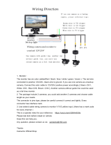
Before operating the camera, confirm that you have the right
camera model and proper power voltage.
In order to help you understand this manual, we'll introduce
our model's description.
DSP color camera for Pan / Tilt / Zoom Control
- 22x Zoom & 16x Zoom (Options : RS-232C, RS-422/ 485)
- 12x Zoom (Options : RS-232C, RS-485)
High Durability Built-in 22x Zoom & 16x Zoom & 12x Zoom
- 22x Zoom (Optical : 22x, Digital : 10x)
- 16x Zoom (Optical : 16x, Digital : 8x)
- 12x Zoom (Optical : 12x, Digital : 10x)
High-Resolution 1/4 inch Color CCD pick-up (22x & 16x Zoom)
High-Resolution 1/3 inch Color CCD pick-up (12x Zoom)
Fuzzy Picture Control with Advance DSP
Powerful Auto Focus
OSD (on-screen display) Function
Wire remote controller (Option)
Digital Slow Sutter for Full color surveillance under
very low light condition : 0.01 Lux (at x 128 Field)
Day & Night Function : 0.5 Lux (B/W)
: Day & Night Model --> 22x Series
12x Series
WIDE
(
-
)
TELE
(+)
MENU
VIDEO OUT
CONTROL
POWER IN
Class 2 Only
+ DC 12V
-
BLC
(SET)
WIDE
(
-
)
MENU
S-VIDEO OUT
VIDEO OUT
CONTROL
POWER IN
Class 2 Only
TELE
(+)
BLC
(SET)
WIDE
(
-
)
MENU
S-VIDEO OUT
VIDEO
CONTROL
POWER IN Class 2 Only
TELE
(+)
BLC
(SET)
NO. NAME FUNCTION
Press TELE (Telephoto) to zoom in.
This button is used for UP in the Menu mode.
Press WIDE (Wide Angle) to zoom out.
This button is used for DOWN in the Menu mode.
1
2
3
4
TELE(+)
WIDE(
-
)
This is an output terminal for separate Y/C
video signals.
5 S-VIDEO
OUT
Connect this terminal to the video input terminal
or an external unit such as a monitor, TV, Time
lapse VCR, multiplexer, swicher etc.
6 VIDEO
OUT
Insert the DC power cable here to connect the
camera to the DC power source(DC 12V).
You can control the Zoom and Focus Lens by using
PT/Zoom controller.
7
POWER IN
and
CONTROL
BLC(SET)
MENU
BLC mode is switched between ON and OFF by
pressing this button.
- This button is used for SET in the menu.
Press Menu to display OSD.
- If you keep pressing MENU over 2 seconds,
OSD will be off.
Menu mode will be displayed again once
Menu is pressed.
Monitor(or DVR)
When using AC 24V power, it is possible to supply the power within 100m.
Use 4 wires by 2 pair of wires.
When using DC 12V power, UTP wire can not be used for power line.
When using UTP video output, set "select switch" at the "UTP OUT".
When the distance is far from camera to monitor, set "select switch" in the middle.
The picture will show a better image.
Connect UTP (Unshielded Twisted Pair) wire to the UTP output of the camera directly.
UTP transmitter is included in the camera therefore additional UTP transmitter is
not necessary.
UTP receiver is necessary to connect UTP wire to Monitor or DVR.
When connecting UTP wire, make sure the polarity of the video signal.
Use UTP wire "CAT5 24AWG" to have the best transmission quality.
Connect the UTP video output terminal on the back of the product to the monitor.
Camera
Video Output
switch select
300m(Max)
Connecting Power
(
For Controller Model
)
Connect Pin 5(Black: GND) and Pin 6(Red: DC12V) of the 6-Pin connector
cable to the output of power adapter according to the following diagram.
Connecting to Monitor / DVR
(
UTP Video Output
)
Connecting Power /
(
For UTP Video out Model
)
DC120.5V
Power Adapter
Power Supply
6-Pin Connector
Cable
Pin Configuration of
6-Pin Circular Connector
[
6-Pin Circular Connector Pins
]
1
2
3
6
5
4
AC 24V
Power Supply
Pin. No
1
2
3
4
5
6
Color
Green
White
Brown/Blue
Yellow
Black
Red
Connecting Power
(
For RS-232C/ RS-422 Communication Model
)
Connect the AC adapter output to the power input terminal of the camera
according to the following diagram.
DC120.5V
Power Adapter
Power Supplying
Terminal
Connecting 6-Pin Connector
(
For Controller Model
)
Link pins 1, 2, and 4 as in the above table,
when using pan/ tilt, zoom controller.
KEY 3
GND 5
POWER
ON/OFF
0.01uF
6.8K 8.2K 12K 18K 33K 68K 180K
MENU TELE(+) WIDE(
-
)
NEGA
ON/OFF
NEAR(+) FAR(
-
)
A/M
(P.AUTO)
: WIRE REMOTE CONTROL KEY FUNCTION
- The 6-Pin connector can be controlled by connecting the external wired
remote control.
- An optional external wired remote controller is provided.
- There are two types of external wired remote controller- 1.5m and 30m.
Connecting KEY:
The following KEY circuit can be configured and used.
Pin.No. N A M E I /O N o t eColor
1
2
3
4
5
6
ZOOM (+:Tele,
-
:Wide)
FOCUS (+:Near,
-
:Far)
KEY
COM(For Zoom, Focus)
GND (For Power)
DC IN
Input
Input
Input
Input
Green
White
Brown
Yellow
Black
Red
6V(Limit +3
~
13V,
-
3
~
-
13V)
6V(Limit +3
~
13V,
-
3
~
-
13V)
DC 12 0.5V
or Blue
Connecting to PC
Connecting 6-Pin Connector
(
For RS-232C Model
)
- RS-232C communication model can be controlled by connecting pins
1, 2 and 4 to the PC as shown in the above table.
- The operating S/W is not provided. Configure the S/W using the protocol
provided by our company.
NAME
1. Frame GND
2. RD
3. TD
4. DTR
5. Signal GND
6. DSR
7. RTS
8. CTS
9. RI
3
4
5
2
1
8
9
7
6
TD
RD
GND
RS-232C D-Sub Connector
TD
RD
GND
NAME
1. Frame GND
2. RD
3. TD
4. DTR
5. Signal GND
6. DSR
7. RTS
8. CTS
9. RI
Connecting to PC (RS-422 Communication)
Connecting to DVR (RS-485)
Connecting 6-Pin Connector
(
For RS-422 Model/ RS-485 Model
)
- RS-422 communications model can be used by connecting pins 1, 2, 3
and 4 in the following diagram.
- The operating S/W is not provided. Configure the S/W using the protocol
provided by our company.
Pin.No. N A M E I /OZoom N o t eColor
1
2
3
4
5
6
Input
Input
Output
Input
Output
Input
Input
22x/ 16x
12x
22x/ 16x
12x
22x/ 16x
12x
22x/ 16x
12x
22x/ 16x
12x
22x/ 16x
12x
R+
RTX+
R
-
RTX
-
T+
KEY
T
-
Line IN
GND
Line IN
DC IN
Green
White
Brown
Yellow
Black
Red
EX. VD (Negative. 5Vp-p)
DC 120.5V
or Blue
Pin.No. N A M E I /OZoom N o t eColor
1
2
3
4
5
6
Input
Output
Input
Input
Input
22x/ 16x
12x
22x/ 16x
12x
22x/ 16x
12x
22x/ 16x
12x
22x/ 16x
12x
22x/ 16x
12x
RD (For RS-232C)
TD (For RS-232C)
KEY
GND
Line IN
GND (For Power)
GND
Line IN
DC IN
Green
White
Brown
Yellow
Black
Red
EX. VD (Negative. 5Vp-p)
DC 120.5V
or Blue
Tx +
Tx
-
Rx +
Rx
-
3
4
5
2
1
8
9
7
6
R +
R
-
T +
T
-
RS-232C D-Sub Connector (PC)
RS-232C TO RS-422 Converter
TRX +
TRX
-
R +
R
-
T +
T
-
DVR (RS-485)
UTP Cable
100m(Max)
UTP Receiver
2 Wire
Explanation of the On-Screen Display
The OSD (On Screen Display) is as follows:
X10000 ID 255
WAIT
X132
1 2 3 4 5 6
7
8
2. Mirror
When IMAGE MIRROR is ON state. The
image is displayed in the opposite direction.
The appear during the mirror mode.
1. Focus
The appear during the focus manual
mode.
4. WBC(White Balance Control) Display
See Page 25.
6. Camera ID Display
See Page 25.
5. Shutter Speed
Use to select the shutter speed.
7. Wait Mode
Indicates the camera stand-by mode
until the camera power turns on.
8. Example of Zoom, Brightness,
Sharpness Display
See Page 25.
3. Back light Display
In case the excessive light is behind the
center object, it is necessary to prevent the
center object from too much darkness.
Turn the BACK LIGHT ON, then the center
object is not influenced by the back light.
FUNCTION OSD Format DESCRIPTION
1
2
3
4
Focus Mode
Mirror Mode
Back Light
WBC Mode
5
Shutter
Speed
Non display
Non display
Non display
Non display
Normal Shutter (NTSC:1/60 PAL:1/50)
8 variable.
7
Wait Mode
Wait Indicates the camera stand-by mode.
until the camera power turns ON.
8.1
Sharpness
Adjustment
Mode Display
8.2
Brightness
Adjustment
Mode Display
8
x15
Zoom
Display
; In case of 22x Zoom (12x Zoom) ; Optical Zoom only mode
; (Current Zoom:x15)
x32
; In case of 44x Zoom ; Digital Zoom x 2 mode
; (Current Zoom:x32)
x150
; In case of 220x Zoom (120x Zoom)
; Digital Zoom x 10 mode
; (Current Zoom:x150)
6
Camera ID
After input the Identification Number to each camera,
Multi-point control is available. (000~255)
Focus Auto Mode
Focus Manual Mode
Mirror Mode OFF
Mirror Mode ON
Back Light OFF
Back Light ON
White Balance AUTO
Push Auto White Balance: In this mode
"Menu key" pressed, the white point traced
automatically (PWB Auto Mode), "Menu Key"
released, the white point preserved currently
(PWB Manual Mode).
Non display
1 / 125
1 / 10000
x18
x10
SHP
Model (NTSC)
Signal System
Scanning System
Scanning Frequency(H)
Scanning Frequency(V)
Image Sensor
Effective Pixels Number
S/N Ratio
Resolution
Video Output Level
Lens
Digital Zoom Ratio
Min. Shooting Distance
Min. Illumination
Sync. System
OSD(On Screen Display)
Shutter Speed (8 Steps)
Input/ Output Connector
Power Consumption
(Option: AC24V/DC12V)
Dimensions (WxHxD)
Weight
22x Series 16x Series
NTSC : 525 Lines
2 : 1 Interlace
15.734 kHz
59.94 Hz
1/4 inch SONY Super HAD CCD
768(H) x 494(V) [Normal : 510 (H) x 492(V)]
More Than 48dB (AGC Off)
Horizontal : 480 TV Lines [Normal : 380 TV Lines]
1.0 Vp-p (75 Ohms, composite)
1 cm (Wide) / 1 meter (Tele)
Day Mode: 1 Lux (30 IRE) / Night Mode : 0.5 Lux (30 IRE)
DSS (128FLD) Mode: 0.001 Lux (30 IRE)
Internal
On / Off
1/60 ~ 1/10,000 Sec.
Control, Power : 6 Pin circle connector / Video Output : BNC
DC 12V (DC 9V
~
15V), Max. 4.2W / 350mA
AC 24V (20V
~
28V) or DC 12V (10V
~
15V), Max 6W/ 0.5A
60 x 60.3 x 101.1 mm 58 x 59.8 x 99.3 mm 52 x 53 x 96.6 mm
Approx. 345g Approx. 330g Approx. 325g
1/3 inch SONY Super HAD CCD
10cm(Wide)/ 0.8meter(Tele)
22x (F1.6, f=3.9~85.8mm) 16x (F1.4, f=4.0~64.0mm) 12x (F1.8, f=5.4~64.8mm)
10x (Total zoom Ratio : 220x) 8x (Total zoom Ratio : 128x) 10x (Total zoom Ratio : 120x)
12x Series
Model
(
PAL
)
Signal System
Scanning System
Scanning Frequency(H)
Scanning Frequency(V)
Image Sensor
Effective Pixels Number
S/N Ratio
Resolution
Video Output Level
Lens
Digital Zoom Ratio
Min. Shooting Distance
Min. Illumination
Sync. System
OSD(On Screen Display)
Shutter Speed (8 Steps)
Input/ Output Connector
Power Consumption
(Option: AC24V/DC12V)
Dimensions (WxHxD)
Weight
22x Series 16x Series
NTSC : 625 Lines
2 : 1 Interlace
15.625 kHz
50 Hz
1/4 inch SONY Super HAD CCD
752(H) x 582(V) [Normal : 500 (H) x 582(V)]
More Than 48dB (AGC Off)
Horizontal : 480 TV Lines [Normal : 380 TV Lines]
1.0 Vp-p (75 Ohms, composite)
1 cm (Wide) / 1 meter (Tele)
Day Mode: 1 Lux (30 IRE) / Night Mode : 0.5 Lux (30 IRE)
DSS (128FLD) Mode: 0.001 Lux (30 IRE)
Internal
On / Off
1/50 ~ 1/10,000 Sec.
Control, Power : 6 Pin circle connector / Video Output : BNC
DC 12V (DC 9V
~
15V), Max. 4.2W / 350mA
AC 24V (20V
~
28V) or DC 12V (10V
~
15V), Max 6W/ 0.5A
60 x 60.3 x 101.1 mm 58 x 59.8 x 99.3 mm 52 x 53 x 96.6 mm
Approx. 345g Approx. 330g Approx. 325g
1/3 inch SONY Super HAD CCD
10cm(Wide)/ 0.8meter(Tele)
22x (F1.6, f=3.9~85.8mm) 16x (F1.4, f=4.0~64.0mm) 12x (F1.8, f=5.4~64.8mm)
10x (Total zoom Ratio : 220x) 8x (Total zoom Ratio : 128x) 10x (Total zoom Ratio : 120x)
12x Series
. Memo
Color Zoom Camera Series
. Memo
Color Zoom Camera Series
C
l
a
s
s
2
O
n
l
y
P
O
W
E
R
I
N
V
I
D
E
O
O
U
T
S
-
V
I
D
E
O
O
U
T
C
O
N
T
R
O
L
W
I
D
E
T
E
L
E
(
-
)
(
+
)
M
E
N
U
(
S
E
T
)
B
L
C
or
DC IN (12V)
Remote Control
(Option 1)
2
3 4
5
61
6 Pin Circle Connector
Connector Cable
.When connecting to the power source, make sure the polarity
of the power adapter is correct.
.Connect power only after installation has been completed.
. AC adapter is sold separately.
Caution
.When connecting to the power source, make sure the polarity
of the power adapter is correct.
.Connect power only after installation has been completed.
. AC adapter is sold separately.
Caution
OWNER'S MANUAL
COLOR ZOOM CAMERA SERIES
DIGITAL POWER ZOOM
Day & Night Color Camera
Day & Night Color Camera
Digital Zoom
Digital Zoom
DSP
DSP
On-Screen Display
OSD
OSD
•
P
o
w
e
r
f
u
l
Z
o
o
m
i
n
g
F
u
n
c
t
i
o
n
&
M
u
l
t
i
-
I
n
t
e
r
f
a
c
e
.
Auto Focus
P/N : 3810-0002F
(Ver.0610E)
Color Zoom Camera Series
Design and specifications
are subject to
change without notice.
Receiver
Remote Control
1 2 3 4
Power
DC 12V, 500mA
RS-485 Signal
- White Terminal :
- Black Terminal :
Camera Selection
- After camera connects with receiver,
firstly check camera I.D.
Menu
(
PROG
)
: Shows / Hides Menu.
Moves up and down items.
(
TELE
)
:
(
WIDE
)
:
- Press camera I.D. number(1
~
39 buttons)
on the top of wireless remote controller.
Caution : Usually camera I.D. number
are selected from No.1 to No.39.
over I.D. No.40, you will have a use limit.
- Initial camera I.D. number is set up No.0
when it takes out of manufacturer's warehouse.
Example: ZOOM IN
I.D. No.5: Press 5 +
<
TELE
>
I.D. No.15: Press
<F1>
+ 5 +
<
TELE
>
I.D. No.24: Press
<F2>
+ 4 +
<
TELE
>
I.D. No.34: Press
<F3>
+ 4 +
<
TELE
>
Set data for the selected items.
(
NEAR
)
:
(
FAR
)
:
F1
NEAR
FAR
FOCUS
F3
WIDE
F2
TELE
ZOOM
AUTO
SEQ PAN
PROG
A
7
4
1
6
9
A
0
8
5
32
The remote controller is optional item.
Cable Connection
Pelco-D/ RS-485
Receiver &
Remote Control
Pelco-D Keyboard
DVR System
Signal (RS-485)
7 ZOOM START
8 ZOOM STOP
9 BRIGHTNESS
10 SHARPNESS
11 FOCUS
12 PROTOCOL
13 INIT SET
END
1
192
48
10
AUTO
DEF
ON
1 BACKLIGHT
2 SLOW SHUTTER
3 DAY / NIGHT
4 WB CONTROL
5 SHUTTER
6 CAMERA
OFF
FLD24
OFF
AUTO
1/10000
123
PROTOCOL(RS-485 only):
DEF : Default
P/D : Pelco-D
PROTOCOL(RS-485 only):
DEF : Default
P/D : Pelco-D
BACKLIGHT :
Use to select BLC mode.
7 ZOOM START
8 ZOOM STOP
9 BRIGHTNESS
10 SHARPNESS
11 FOCUS
12 PROTOCOL
13 INIT SET
END
1
192
48
10
AUTO
DEF
ON
/