
1
2501en EXCOUNT-II Users Manual
Users manual
EXCOUNT-II

2
2501en EXCOUNT-II Users Manual
Legal disclaimer
Any responsibility or liability for loss or damage in connection with the
use of this product and the accompanying documentation is disclaimed.
The information in this document is furnished for informational use only, is
subject to change without notice, may contain errors or inaccuracies, and
represents no commitment whatsoever.
Federal Communications Commission Statement
This device complies with part 15 of the FCC Rules. Operation is subject
to the following two conditions:
(1) this device may not cause harmful interference, and
(2) this device must accept any interference received, including interfe-
rence that may cause undesired operation.
WARNING!
Any changes or modications to this product not expressly
approved by the manufacturer could void any assurances of
safety or performance and could result in violation of Part 15 of
the FCC Rules.
Trademark acknowledgements
Windows 95, 98, ME, NT4 and 2000 are registred trademarks of
Microsoft Corporation.
Safety instructions
Do not connect the Transceiver to other voltage sources than a standard
9 volt battery type 6LR61/PP3
Ensure that the battery is connected correctly.
The Transceiver contains a radio transmitter and receiver which must not
be used where the use of radio transmitters or other electronic devices
is prohibited.
WARNING!
All work related to the EXCOUNT-II´s sensors and the surge arresters
shall be made with disconnected and earthed conductors. Follow all
regulations and rules stated by international or national safety regula-
tions.
Normally, the EXCOUNT-II´s sensors and the surge arresters operate at
a high voltage. Therefore they must be installed in such a way that only
qualied personnel has access to them.

3
2501en EXCOUNT-II Users Manual
EXCOUNT-II is an advanced surge arrester monitor for effectively, reliably
and safety monitoring and recording surges on high voltage electrical
networks.
EXCOUNT-II incorporates a sensor, which is mounted on the surge
arrester, a transceiver, for remote reading and a PC-program (Windows
95/98/2000/ME and NT).
This users manual desribes the functions of EXCOUNT-II to give you total
control over surge monitoring.
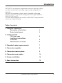
Table of contents
1. Using the transceiver
Description of the buttons 4
Normal maintenance 4
2. Getting started
First time usage 5
Installation/uninstallation
of software 5
Administration of sensors 6
3. Flowchart, make measurements 7
4. Transceiver symbols 8
5. Transceiver menu system 9
6. Transceiver error codes 14
8. Sensor installation 16
9. More information 19
Introduction

4
2501en EXCOUNT-II Users Manual
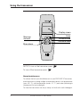
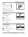
Enter
Increase value
Display screen
Decrease value
Move down
Move up
Go back
NOTE! To turn on the transceiver press
To turn off the transceiver press
Normal maintenance
To achieve the best possible lifetime out of your EXCOUNT-II Transceiver,
avoid exposure to strong sunlight for extended periods, hot temperatures
(over +50 º C), cold temperatures (under -10 º C ) and water (the design is
showerproof but not watertight).
To clean the transceiver use only a damp soft cloth with a mild detergent.
Using the transceiver

5
2501en EXCOUNT-II Users Manual
Getting started
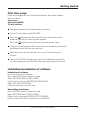
First time usage
Open the package and verify that the following items are present together
with this manual:
Transceiver
Data cable (RS232)
CD with software
Familiarize yourself with the above safety instructions.
Fit a new 9 volt battery type 6LR61/PP3.
Press the button on the front panel and verify that the transceiver
powers up and that the stand-by menu appears.
Press the button and verify that the transceiver powers down.
Using this manual together with the transceiver and familiarize yourself with
the different menus and how they are used.
Particulary ensure that the date and clock on the Transceiver are set
correctly.
Load the EXCOUNT-II software onto your PC and famliarize yourself with
its use by reading the individual HELP les within each respective section.
Installation/unistallation of software
Installation of software
Insert the CD into your computer.
Press the START button in lower left corner
Select SETTINGS then CONTROL PANEL
Double-click on the icon ADD/REMOVE PROGRAMS
Select ADD NEW PROGRAMS
Follow the instructions on the screen
Uninstalling of software
Press the START button in lower left corner
Select SETTINGS then CONTROL PANEL
Double-click on the icon ADD/REMOVE PROGRAMS
Browse to the EXCOUNT-II software and click REMOVE

6
2501en EXCOUNT-II Users Manual
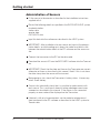
Administration of Sensors
Fit the sensor to the arrester as described in the installation instructions
supplied with it.
Record the following details as specied in the EXCOUNT-II HELP system
for administration:
station data
arrester data
EXCOUNT-II data
Input this data into the software as described in the HELP system.
IMPORTANT! After installation of a new sensor and input of the adminis-
tration details, an initial reading must always be made to establish a link
between the administration details in the PC software and the sensor on
site.
Connect the transceiver to the PC via the data cable
Download the sensor’s ID from the EXCOUNT-II software into the Transcei-
ver.
IMPORTANT! Check that the date and time on the Transceiver are correct,
otherwise set them as described in this manual. Note! If this is not done
the date stamp from the sensor will be incorrect.
Before going to site, check the Transceiver’s battery status. If necessary,
install a new battery.
Once at site, individually check that it is possible to make contact with
each sensor. This is most easily done by taking a leakage current mea-
surement as described in this manual. If the sensor is not connected
properly, an error code will be displayed on the Transceiver.
If desired, a full set of measurements can be made for reference and
then transferred to the PC software as described in the HELP system for
Transfer data.
Getting started

7
2501en EXCOUNT-II Users Manual
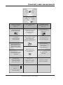
Flowchart, make measurements
The main menu is
accessed by pressing
enter
Press to turn
on the transceiver
1. Prepare the transceiver
for measurements
See 1.1.1
Set the transceiver to
"Prepare the transceiver
for measurements" mode.
Connect the
transceiver to the PC
via the data cable.
Select which Sensors are to
be read by station, position
and phase.
Select Sensor ID from
the menu in the transceiver
and press enter.
Different types of
measurements can be
performed by following
the instructions in 1.3.
Click "Send list to
transceiver" when ready.
This erases all stored
data in the transceiver.
2. Make measurements
See 1.3
3. Transmit data to the
EXCOUNT-II software
See 1.1.2
Set the transceiver to
"Data transfer from Transceiver
to PC" mode.
Connect the transceiver to
the PC via the data cable
Open the EXCOUNT-II
PC software and select "Transfer
data" followed by
"Receive measured data
from transceiver".
Click "Request data"
when ready.
Click "save" to store the
details in the database.
Before going to the site
check the battery status.
See 1.2.
Then turn off the transceiver
to save the batteries.
Ensure the sensor to be read
is within the range for
transmission (normally
up to 60 m).
Set the transceiver to "Make
measurements" mode.
Select type of measurement by
following the instructions in 1.3.
Open the EXCOUNT-II PC-
software and select "Transfer
data" followed by "Prepare
transceiver for measurement".

8
2501en EXCOUNT-II Users Manual
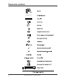
Transceiver symbols
ABB
>>>>>>>

9
2501en EXCOUNT-II Users Manual
Transceiver menu system
ABB
2.0.0 E
Stand-by
Turn the transceiver on by pressing
Turn the transceiver off by pressing
Got to the main menu by pressing
The transceiver turns itself off automatically
after 5 minutes.
The program version is shown in the lower
left corner. The E stands for extended version which
includes resistive leakage current measurement.
1. Main menu
Select alternative with the key.
Then press the
Transfer data (see 1.1)
Battery check (see 1.2)
Make measurements (see 1.3)
Set clock and date (see 1.4)
Back to stand-by
1.1 Transfer data
Select alternative with the key.
Then press the
Data transfer from PC to Transceiver (see 1.1.1)
Data transfer from Transceiver to PC (see 1.1.2)
Back to main menu

10
2501en EXCOUNT-II Users Manual
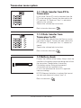
1.1.1 Data transfer from PC to
Transceiver
In this mode, Sensor ID’s can be transfered from the
PC to the transceiver. Connect the data cable to the
PC serial port. PC Serial port Com 1 is selected as
default by the software.
See also the software help instructions.
Back to transfer data menu
Transceiver menu system
1.1.2 Data transfer from
Transceiver to PC
In this mode data collected from the Sensors can be
transmitted to the PC. Connect the data cable to the
PC serial port. PC Serial port Com 1 is selected as
default.
See also the software help instructions.
Back to transfer data menu
0 % 100%
1.2 Battery check
Displays the condition of the battery. Always check the
condition of the battery before transfering data to/from
the transceiver. Change battery if necessary.
If the battery expires during a measurement
session,data can be corrupted or lost.
In such case download the sensor ID’s again and
take new readings.
NOTE! Whenever the battery is replaced the transcei-
ver clock and date must be reset. (see 1.4)
Back to main menu

11
2501en EXCOUNT-II Users Manual
S
A
A
1.3 Make measurements
Select alternative with the key.
Then press the
Leakage current measurement (see 1.3.1)
Read surge counter data (see 1.3.2)
Resistive leakage current measurement (see 1.3.3)
Full measurement (all of the above)
Back to main meny
Transceiver menu system
1.3.1 Leakage current measurement
Select sensor ID to read data from with the
Start the reading by pressing
A successful transmission is marked with
A failed transmission is marked with
If the transmission was unsuccessful, an error code
will be displayed.
Back to read data menu
Progress bar Error code
1.3.2 Read surge counter data
Select sensor ID to read data from with the key.
Start the reading by pressing
A successful transmission is marked with
A failed transmission is marked with
If the transmission was unsuccessful, an error code
will be displayed.
Back to read data menu
Progress bar Error code

12
2501en EXCOUNT-II Users Manual
Transceiver menu system
1.3.3 Resistive leakage current
measurement *
)
Select sensor ID to read data from with the key.
Start the reading by pressing
Before the transmission begins the operating voltage
must be given. (see 1.3.3.1)
A successful transmission is marked with
A failed transmission is marked with
If the transmission was unsuccessful, an error code
will be displayed.
Back to read data menu
*
)
Not available in all versions.
Progress bar Error code
1.3.3.1 Operating voltage *
)
The actual operating voltage must be given when
measuring the resistive leakage current.
The system voltage is displayed as a default value.
Adjust the value to the actual value with
and keys.
Enter the correct value by pressing
NOTE! If the system is 3-phase, the value should
be the actual phase-phase voltage. Otherwise, for
1-phase systems, the value should be the phase-
ground voltage.
The progress bar will indicate that the transmission
has begun.
*
)
Not available in all versions.

13
2501en EXCOUNT-II Users Manual
Transceiver menu system
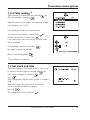
1.3.4 Total reading *
)
Select sensor ID to read data from with the key.
Start the reading by pressing
Before the transmission begins, the operating voltage
must be given. (see 1.3.3.1)
Each reading is made in turn automatically.
A successful transmission is marked with
A failed transmission is marked with
If the transmission was unsuccessful, an error code
will be displayed
If any reading is unsuccessfull press
key again to repeat the reading.
Back to total reading menu
*
)
Not available in all versions.
1.4 Set clock and date
The cursor highlights which digit to adjust. The cursor
is moved to the next digit by pressing the key.
Each digit is changed by using the and
keys.
After changing any digit the status symbol is changed
to X .
When the correct date and clock is set move the
cursor to the X and enter the value by
pressing
This changes the status symbol to

14
2501en EXCOUNT-II Users Manual
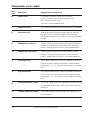
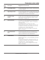
Transceiver error codes
Error
code
01
11
21
31
32
41
42
51
52
Description
System error
Prohibited action
Checksum error
EEPROM data read error
EEPROM data write error
Low temperature
High temperature
Too low eld probe current
Too high eld probe current
Suggested cause and action
Turn off the transceiver and re-start. If the error
persists, a serious internal fault has occurred with
the Transceiver. Contact your
EXCOUNT-II service representative.
The user has attempted to do something which is prohibited.
An error occurred in the data transmission and the data
has been lost or corrupted. Interference from a nearby
cellular/mobile phone can be a likely cause. Try to re-transmit
the data.
The transceiver could not read from the internal EEPROM
memory. Turn off the transceiver and re-start. If the error
persists, contact your EXCOUNT-II service representative.
The transceiver could not write to the internal EEPROM
memory. Turn off the transceiver and re-start. If the error
persists, contact your EXCOUNT-II service representative.
The ambient temperature is lower than dened in the data-
base for resistive current measurements. (Lowest dened
temperature is -10 º C). Take new measurements at another
time.
The ambient temperature is higher than dened in the data-
base for resistive current measurements. (Highest dened
temperature is +60 º C). Take new measurements at another
time.
The system voltage is too low to generate sufcient current in
the eld probe in the sensor. Check that the line is correctly
energised.
The system voltage is too high. Check that the line is cor-
rectly energised.

15
2501en EXCOUNT-II Users Manual
Transceiver error codes
Suggested cause and action
The measured leakage current is too low. Check that the line
is correctly energised.
The measured leakage current is too high. Check that the line
is correctly energised. If so, try taking another measurement.
If the error persits, the arrester may be suspect.
A stable value for the leakage current cannot be measured.
A likley cause may be an unstable line voltage. Take new
measurements at another time.
The sensor ID was not recognised by any locally present
sensor. Try retransmitting again. If contact still cannot be
established, check:
a) the chosen sensor ID is present at this station
b) the distance to the sensor is not too far (max 60 m, but
can depend on interference from buildings and structures)
c) interference from a cellular/mobile phone
d) battery status to ensure the voltage in the transceiver
battery is not too low
Turn off the transceiver and re-start. If the error persists,
a serious internal fault has occurred with the Transceiver.
Contact your EXCOUNT-II service representative.
The sensor recognised it’s ID but the connection was lost
during the transmission. Try re-transmiting again. If the error
persists, check:
a) the distance to the sensor is not too far (max 60m, but
can depend on interference from buildings and structures).
b) interference from a cellular/mobile phone.
c) battery status to ensure the voltage in the transceiver
battery is not too low.
Description
Low leakage current
High leakage current
Unstable leakage
current
Sensor not found
Transmission buffer
error
Connection lost
Error
code
61
62
70
80
81
82

16
2501en EXCOUNT-II Users Manual
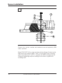
Sensor installation
1
Screws, nuts, sockets, washers and conductors are not supplied by ABB
unless specied.
Mount EXCOUNT-II (3) on surge arrester´s bottom ange (4) above insula-
ting base (5) according to gure 1 and 2. Do not place close to venting
duct (if any). Bolt joint (1 and 2) is supplied with ABB insulating base (5).
Fittiing and tightening torque according to instructions supplied with
insulating base.

17
2501en EXCOUNT-II Users Manual
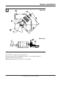
Sensor installation
2
EXCOUNT-II is used as earth connection.
Connect earth cable with tinplated socket (7) according to gure 2.
Recommended screw: M12 (6)
Tightening torque for M12: 84 Nm, use washers
Top view
Side view

18
2501en EXCOUNT-II Users Manual
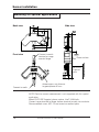
Sensor installation
Mounting for special applications
NOTE! Resistive current measurement is not supported with this special
application.
Mount EXCOUNT-II against planar surface. Use 2 X M6 bolts.
Connect upper terminal to ange, bottom terminal to earth via conductor.
Recommended screw: M12. Do not mount on earthed plate.
Back view Side view
Front view
Antenna area, min distance
to groundplane: 60 mm
Planar surface
Connect to earth
terminal on surge
arrester ange
Connect to earth
Min 60 mm
to ground
plane

19
2501en EXCOUNT-II Users Manual
More information
For more information about EXCOUNT-II and for downloading updates of
the EXCOUNT-II software, please visit:
http://www.abb.com/arrestersonline
Select HIGH VOLTAGE SURGE ARRESTERS (HV)
Select EXCOUNT-II

20
2501en EXCOUNT-II Users Manual
PTHVP/A 2501 en, Edition 1 02-02
ABB Power Technology Products AB
High Voltage Products
Surge Arresters
SE-771 80 LUDVIKA, Sweden
Tel. +46 (0)240 78 20 00
Fax. +46 (0)240 179 83
E-mail: [email protected]
Internet: http://www.abb.com/arrestersonline
-
 1
1
-
 2
2
-
 3
3
-
 4
4
-
 5
5
-
 6
6
-
 7
7
-
 8
8
-
 9
9
-
 10
10
-
 11
11
-
 12
12
-
 13
13
-
 14
14
-
 15
15
-
 16
16
-
 17
17
-
 18
18
-
 19
19
-
 20
20


Ask a question and I''ll find the answer in the document
Finding information in a document is now easier with AI
Related papers
Other documents
-
H3C SecPath F5030-D Installation guide
-
H3C SecPath F1010 Installation guide
-
H3C WX3024E Installation guide
-
JRC JSS-896 - User manual
-
-
COBHAM SAILOR 6000B Installation guide
-
-
3com H3C SECPATH F5000-A5 ADVANCED VPN FIREWALL 12-PORT GIGABIT ETHERNET MODULE Installation guide
-
-