
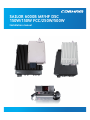
SAILOR 6000B MF/HF DSC
Installation manual
150W/150W FCC/250W/500W


Table of Contents
SAILOR 6000B MF/HF DSC
150W/150W FCC/250W/500W
Installation manual
Document number: 98-144591-D
Release date: December, 2016

98-144591-D
ii
Disclaimer
Any responsibility or liability for loss or damage in connection with the use of this product and the accompanying
documentation is disclaimed by Thrane & Thrane A/S. The information in this manual is provided for information
purposes only, is subject to change without notice and may contain errors or inaccuracies. Manuals issued by Thrane
& Thrane A/S are periodically revised and updated. Anyone relying on this information should acquire the most
current version e.g. from www.cobham.com/satcom, Service and support, or from the distributor. Thrane & Thrane
A/S is not responsible for the content or accuracy of any translations or reproductions, in whole or in part, of this
manual from any other source. In the event of any discrepancies, the English version shall be the governing text.
Thrane & Thrane A/S is trading as Cobham SATCOM.
Copyright
© 2016 Thrane & Thrane A/S. All rights reserved.
Trademark Acknowledgements
• Thrane & Thrane is a registered trademark of Thrane & Thrane A/S in the European Union and the Unites
States of America.
• SAILOR is a registered trademarks of Thrane & Thrane A/S.
• Other product and company names mentioned in this manual may be trademarks or trade names of their
respective owners.

iii98-144591-D
Safety summary
The following general safety precautions must be observed during all phases of operation, service and repair of this
equipment. Failure to comply with these precautions or with specifi c warnings elsewhere in this manual violates
safety standards of design, manufacture and intended use of the equipment. Thrane & Thrane assumes no liability
for the customer's failure to comply with these requirements.
GROUND THE EQUIPMENT
To minimise shock hazard, the equipment chassis and cabinet must be connected to an electrical ground and the
cable instructions must be followed.
DO NOT OPERATE IN AN EXPLOSIVE ATMOSPHERE
Do not operate the equipment in the presence of fl ammable gases or fumes.
Operation of any electrical equipment in such an environment constitutes a defi nite safety hazard.
KEEP AWAY FROM LIVE CIRCUITS
Operating personnel must not remove equipment covers. Component replacement and internal adjustment must be
made by qualifi ed maintenance personnel. Do not service the unit with the power cable connected. Always discon-
nect and discharge circuits before touching them.
Service
General service must be done by skilled service personnel.
Caution! Only skilled service personnel may service and repair the equipment.
Always carry out work under ESD safe conditions.

98-144591-D
iv
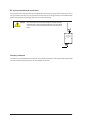
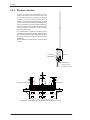
RF exposure hazards and instructions
Your Thrane & Thrane radio generates electromagnetic RF (radio frequency) energy when transmitting. To ensure
that you and those around you are not exposed to excessive amounts of energy and thus to avoid health hazards
from excessive exposure to RF energy, all persons must obey the following:
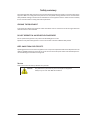
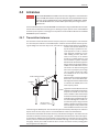
Caution! Never touch the horn of the Antenna Tuning Unit or feeder wire when
the MF/HF
radio is transmitting. High voltage which can cause death
or serious injury is present at the locations shown in the illustration
below.
Warranty limitation
The radio is not a user maintainable unit, and under no circumstances should the unit be opened except by authorized
personnel. Unauthorized opening of the unit will invalidate the warranty.
Unit
Antenna Tuning
MF/HF
SAILOR 638x

v98-144591-D
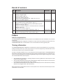
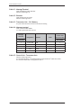
Record of revisions
Rev. Description Relase Date Initials
A Original document October 2015 CMA
B Installation is changed - page vi
Warning is changed - page v
Drawing updated - page 2-24.
Setup menu updated - page 2-26
Cable names are changed (AUX & SYS) - pages 2-18, 2-20, 2-21
Accessory list updated - page 5-8 November 2015 CMA
C Technical data, - Antenna added - page 1-1
Input impedance 20 mA changed to 60 mA - page 1-3
Chapter 1.2.4, Input impedance, Sensitivity, Intermodulation, Spurious
rejection are removed - page 1-4
Chapter 2.4.1 Headline changed from 'Transceiver Antenna' to 'Transmitter
Antenna' - page 2-12
Chapter 2.4.3 is rewritten - page 2-15
RX Antenna & TX Antenna added confi g. drawing - page 2-18 February 2016 CMA
D Chapter 4.1 pkt. 6 added - page 4-1
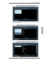
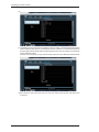
Chapter 4.2 Calibrating the master oscillator added - page 4-1 December 2016 CMA
Preface
Radio for occupational use
The SAILOR 6000B MF/HF DSC fulfi ls the requirements of the SOLAS directive and is intended for use in maritime
environment.
SAILOR 6000B MF/HF DSC is designed for occupational use only and must be operated by licensed personnel only.
SAILOR 6000B MF/HF DSC is not intended for use in an uncontrolled environment by general public.
Training information
The SAILOR 6000B MF/HF DSC is designed for occupational use only and is also classifi ed as such. It must be ope-
rated by licensed personnel only. It must only be used in the course of employment by individuals aware of both
the hazards as well as the way to minimize those hazards.
The radio is thus NOT intended for use in an uncontrolled environment by general public. The SAILOR 6000 MF/HF
DSC has been tested and complies with the FCC RF exposure limits for Occupational Use Only. The radio also com-
plies with the following guidelines and standards regarding RF energy and electromagnetic energy levels including
the recommended levels for human exposure:
• FCC OET Bulletin 65 Supplement C, evaluating compliance with FCC guidelines for human exposure to radio
frequency electromagnetic fi elds.
• American National Standards Institute (C95.1) IEEE standard for safety levels with respect to human exposure
to radio frequency electromagnetic fi elds, 3 kHz to 300 GHz
• American National Standards Institute (C95.3) IEEE recommended practice for the measurement of potentially
hazardous electromagnetic fi elds - RF and microwaves.
Below the RF exposure hazards and instructions in safe operation of the radio within the FCC RF exposure limits
established for it are described.

98-144591-D
vi
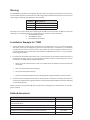
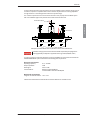
Warning
The SAILOR radio set generates electromagnetic RF (radio frequency) energy when transmitting. To ensure that no
personnel will be exposed to excessive amounts of RF-energy and to avoid health hazards from excessive exposure
to RF energy, the following safety distances must be followed:
Antenna Safety distance
150W Calculated: 1.71 m or 5.7 feet
250W Calculated: 2.21 m or 7.3 feet
500W Calculated: 3.12 m or 10.3 feet
Calculations cover a whip antenna with a maximum gain of 3dBi, worst case frequency (30 MHz), full power and
100% duty cycle (transmitter always on) considering the most conservative limits mentioned in:
FCC OET Bulletin 65 (1997)
Canada RSS102 (2010)
Canada Safety Code 6 (2015)
Installation Example for 150W
1. A whip antenna with a maximum gain of 3 dBi must be mounted at least 12.3 ft. (3.71m) above the highest
deck where people may be staying during continuous radio transmissions. The distance is to be measured
vertically from the lowest point of the antenna. This provides the minimum separation distance which is in
compliance with RF exposure requirements and is based on the MPE radius of 5.7 feet (1.71 m) plus the 6.6 ft.
(2.0 m) height of an adult.
2. On vessels that cannot fulfi ll requirements in item 1, the antenna must be mounted so that the lowest point of
the antenna is at least 5.7 feet (1.71m) vertically above the heads of people on deck and all persons must be
outside the 5.7 feet MPE radius during radio transmission.
• Always mount the antenna at least 5.7 feet from possible human accessNever touch the antenna when
transmitting.
• Never touch the antenna when transmitting.
• Use only authorized T&T accessories.
• Only allow trained and certifi ed operators knowing about RF-energy and hazards to operate the radio.
3. If the antenna has to be placed in public areas or near people with no awareness of the radio transmission, the
antenna must be placed at an even greater distance. Consult the appropriate standard for exact limits, depending
on national specifi cations.
Failure to observe any of these warnings may cause RF exposure exceeding above mentioned limits or create dan-
gerous conditions..
Related documents
Title and description Document number
Installation guide SAILOR 630x MF/HF Control Unit 98-132396
Installation guide SAILOR 6000B MF/HF Transceiver Unit & Antenna Tuning Unit
150 W/250 W/500 W
98-144542
User Manual SAILOR 6301 MF/HF Control Unit 98-131070
User Manual SAILOR MF/HF System 6000A/6000B MF/HF Radiotelex 98-151795
Installation and user manual SAILOR 6101 and 6103 Alarm Panel 98-130981
Emergency call sheet 98-132369

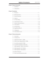
Table of Contents
vii
98-144591-D
Chapter 1 General information
1.1 Introduction .............................................................................................................................1-1
1.2 Technical data ...........................................................................................................................1-1
Chapter 2 Installation
2.1 Description .................................................................................................................................2-1
2.2 Mounting the units .................................................................................................................2-1
2.3 Ground connections .............................................................................................................2-9
2.4 Antennas .....................................................................................................................................2-12
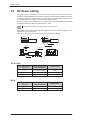
2.5 DC Power cabling ...................................................................................................................2-17
2.6 Interconnection of units .....................................................................................................2-18
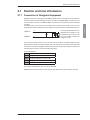
2.7 Position and time information ..........................................................................................2-25
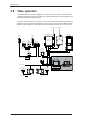
2.8 Telex operation ........................................................................................................................2-26
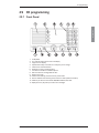
2.9 ID Programming .......................................................................................................................2-27
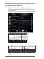
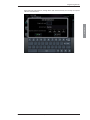
2.10 Programming Telex ID .........................................................................................................2-29
2.11 Confi guration ...........................................................................................................................2-31
2.12 Final installation check .........................................................................................................2-35
Chapter 3 Technical description
3.1 Control Unit ...............................................................................................................................3-1
3.2 Transceiver Unit .......................................................................................................................3-1
3.3 Supply Filter module 57-139985 ....................................................................................3-1
3.4 Exciter Control module (ECM) 60-139984 ...............................................................3-1
3.5 PA and Filters module 60-122881..................................................................................3-2
3.6 PA and Filters module 60-123937 (FCC) ...................................................................3-3
3.7 SMPS module 60-122882 (150 W/250 W) ...............................................................3-3
3.8 SMPS module 60-126172 (500 W) ...............................................................................3-3
3.9 SMPS module 60-126236 (500 W) ...............................................................................3-4
3.10 Antenna Tuning Unit ............................................................................................................3-4
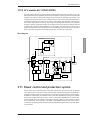
3.11 Power control and protection system ...........................................................................3-6
Table of Contents

98-144591-D
viii
Table of Contents
Chapter 4 Service
4.1 Preventive maintenance .....................................................................................................4-1
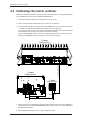
4.2 Calibrating the master oscillator ......................................................................................4-2
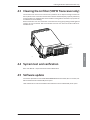
4.3 Cleaning the Air fi lter (500 W Transceiver only) ......................................................4-5
4.4 System test and verifi cation ..............................................................................................4-5
4.5 Software update ......................................................................................................................4-5
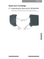
Chapter 5 Spare part exchange
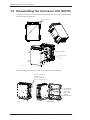
5.1 Disassembling the Transceiver Unit (150 W/250 W) ............................................5-1
5.2 Disassembling the Transceiver Unit (500 W) ............................................................5-2
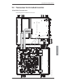
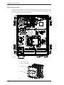
5.3 Transceiver Unit module location ...................................................................................5-3
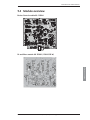
5.4 Module overview .....................................................................................................................5-5
5.5 Required service tools ...........................................................................................................5-8
5.6 Accessory list ............................................................................................................................5-8
Glossary ................................................................................................................... Glossary-1

Chapter 1: General information
1-1
General information
98-144591-D
Technical data
General information
1.1 Introduction
The 150 W/250 W/500 W MF/HF transceiver with integrated DSC and telex (NBDP) is designed for mari-
time applications in voluntary as well as compulsorily fi tted vessels. It offers simplex and semi-duplex
SSB radiotelephone communication in the maritime mobile frequency bands between 1.6 and 30 MHz.
The basic version of the transceiver includes voice, DSC and a dedicated 2187.5 KHz DSC watch receiver,
forming an ideal system for MF GMDSS installations.
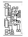
The equipment consists of a compact transceiver control unit, a fully remote controlled transceiver unit
and an automatic antenna tuning unit.
The microprocessor controlled Antenna Tuning Unit automatically matches the impedance of antennas
between 8 and 18 metres in length and requires no presetting at the installation. It is designed for outdoor
installation and may be located up to 100 metres from the Transceiver Unit.
The Transceiver Unit contains all receiver and transmitter circuits. The fully protected solid state 150 W/
250 W /500 W power amplifi er matches a 50 ohm antenna system, but is normally used in connection
with the Antenna Tuning Unit. The DSC/Telex modem contains two demodulators, one connected to the
built-in watch receiver for continuous watch on the DSC distress frequencies, the other connected to
the communication receiver which may be used to keep simultaneous watch on other DSC frequencies
or telex communication.
The transceiver can be upgraded to scan 6 DSC channels, and Telex operation to comply with MF/HF
requirements in sea area A4. Codes are purchased as accessories for the system.
The Control Unit is for operation of radiotelephony as well as DSC and confi guration. Use of the equip-
ment is simple, logic and straight forward. DSC operation is based on the use of soft keys. Guiding texts
are provided and the large display is able to show the contents of a complete call in one screen.
For telex operation the Message Terminal must be connected to the system via the CAN bus.
The equipment is designed for operation from a 24 V DC supply, like e.g. a battery. With the optional AC
Power Supply unit installed the equipment may be supplied from 115/230 V AC main or emergency sup-
plies with automatic switch-over to 24 V DC supply in the absence of AC supply voltage. Also optionally, a
battery charger for AC is available in the product line.
The built-in test facilities and easy-to-replace module design of the equipment simplifi es the service concept.
1.2 Technical data
1.2.1 General
Complies with the relevant IMO performance standards for MF, MF/HF, MSI, and NBDP GMDSS equipment,
the ITU Radio Regulations, the ITU-R recommendations and the relevant performance specifi cations of
ETSI, IEC and FCC, in the ITU marine bands.
Operating modes: Simplex and semi-duplex SSB telephony (J3E), DSC (J2B), AM broadcast
reception (H3E) and Telex (J2B)
Antennas: The Transceiver is designed to operate as a "two antenna simplex/semi-
duplex" confi guration only, meaning that separate antennas are used for
reception (RX) and transmission (TX) respectively.
Frequency stability: Better than 0.35 ppm
Warm-up time. Less than one minute
Ageing less than 0.1 ppm/year
Normal operating
temperature: from 0°C to +40°C
Extreme operating
temperature: From -15°C to +55°C
ATU From -25°C to +55°C
Chapter 1: General information
Chapter 1

1-2
Chapter 1: General information 98-144591-D
Technical data
User-programmable
channels: 199 frequency pairs with mode (1-199)
User-programmable
stations: 40 stations with name, MMSI and station channel
Supply voltage: Nominal 24V DC (-10 +30% — 21.6 - 31.2 V DC)
With optional external AC power supply:
115/230V AC 50/60 Hz. Automatic change-over to DC in the absence of AC supply
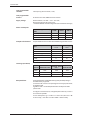
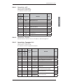
Power consumption:
Rx Mode: Approximately
45W
150 W 250 W 500 W
Tx, SSB speech 175 W 300 W 600 W
Tx, SSB two-tone 300 W 550 W 1100 W
Tx, DSC/TELEX 310 W 600 W 1000 W
Compass safe distance:
Compass safe distance in accordance with ISO/R 694 are given below in metres
Unit
Standard
5.4°/H
Steering
18°/H
Control Unit 1.2 0.5
Transceiver Unit 0.85 0.25
Antenna Tuning Unit 0.6 0.3
Handset 0.3 0.2
Cradle 1.1 0.7
Loudspeaker 2.2 1.6
IP ratings (estimated):
System Transceiver Unit
Antenna Tuner
Unit *
Control Unit
150 W IP43 IP56 IP54
250 W IP43 IP56 IP54
500 W IP20 IP56 IP54
* Antenna cable must be carefl ly installed to obtain this IP rating
Dissipated heat: The dissipated heat in standby RX mode is typically 45 W depending on
attached ancillary equipment.
In transmit mode, use the consumption fi gures for the appropriate mode,
multiplied by 0.66.
E.g. 0.66 x 175 W = 115.5 W dissipated heat for a 150 W system in SSB
speech mode.
For a fi gure in kilocalories (kcal), multiply dissipation effect by on-time in
hours and then by 0.860.
For the 150W system, e.g. 115.5 W x 2 h + 45 W x 22 h (TX 2 hours + RX
22 hours a day) = 1221 Wh. 1221 Wh x 0.860 ~ 1050 kcal a day.

Chapter 1: General information
1-3
General information
98-144591-D
Technical data
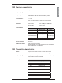
1.2.2 Receiver characteristics
General: Complies with ETSI 300373 in the ITU marine bands.
Frequency range: 150 KHz to 30 MHz
Frequency resolution: 100 Hz by keyboard entry
10 Hz, 100 Hz or 1 KHz search/fi ne-tune facility is provided
Input impedance: Rx : 50 ohm
12V DC / 60 mA is available for possible use of active antenna.
Sensitivity: Telephony (J3E): below 11 dBμV for 20 dB Sinad
Broadcast (A3E): below 25 dBμV for 20 dB Sinad
DSC/Telex (J2B): below 0 dBμV
Intermodulation:
Wanted signal Signal
Telephony (J3E) 30 dBμV
Intermodulation level
above 80 dBμV
Telex (J2B) 30 dBμV
Intermodulation level above 90 dBμV
DSC (J2B) 20 dBμV
Intermodulation level above 80 dBμV
Spurious rejection: Above 70 dB
Audio output power: Build-in loudspeaker 6 W typical.
Optional loudspeaker output 6 W typical with less than 10 % distortion.
Output intended for 8 ohm loudspeaker.
1.2.3 Transmitter characteristics
General: Complies with ETSI 300373 and FCC in the ITU marine bands.
The Transmitter characteristics are with the Antenna Tuning Unit included.
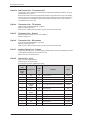
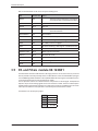
Frequency range: All frequencies in the range 1605 KHz to 30 MHz however by factory
default arranged in the ITU marine bands.
Factory pre-programmed:
Band Frequency
00 1.605 - 4.000 MHz
01
4.000 - 4.438 MHz
02 6.200 - 6.525 MHz
03 8.100 - 8.815 MHz
04 2.230 - 13.200 MHz
05 6.360 - 17.410 MHz
06 8.780 - 18.900 MHz
07 19.680 - 19.800 MHz
08 22.000 - 22.855 MHz
09 25.070 - 25.210 MHz
10 26.100 - 26.175 MHz

1-4
Chapter 1: General information 98-144591-D
Technical data
Frequency resolution: 100 Hz
Output impedance: TX: 50 ohm
The Antenna is matched by the Antenna Tuning Unit
Power reduction: Low power: 20 W PEP
Intermodulation: below -31 dB/PEP
Spurious Emission: below -43 dB/PEP
below -60 dB/PEP (FCC)
Hum and noise: Less than - 40 dB/PEP
Output power 150 W SSB: ± 1.4 dB into 50 ohm Antenna.
DSC/Telex:
85 W ± 1.4 dB
Output power 250 WSSB: ± 1.4 dB into 50 ohm Antenna.
DSC/Telex:
125 W ± 1.4 dB
Output power 500W SSB: 1.6-4 MHz 400 W PEP +0/-1.4 dB
4-27 MHz 500 W PEP ±1.4 dB into 50 ohm Antenna.
DSC/Telex:
250 W ± 1.4 dB
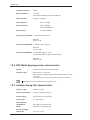
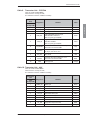
1.2.4 DSC Watch keeping receiver characteristics
General: Complies with ETSI 300338 and ETSI 301033.
Frequency range: Default set to D1 - 2187.5 KHz.
When scanning is enabled by option code it will default be D6 - 2-4-6-8-
12-16 MHz.
Can be reduced to minimum 3 frequencies via the Service Interface.
Regarding further receiver characteristics refer to section 1.2.2.
1.2.5 Antenna Tuning Unit characteristics
Frequency range: 1.6 MHz - 27.5 MHz
Antenna requirements: 8-18 m wire and/or whip antenna
Antenna tuning: Fully automatic with no presetting
Tuning speed: 0.1 - 8 sec. (typical)
Power capability
150 W/250 W: 350 W PEP into 50 ohm antenna
500 W: 600 W PEP into 50 ohm antenna
Extreme operating
temperature: from -25°C to +55°C

Chapter 1: General information
1-5
General information
98-144591-D
Technical data
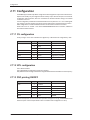
1.2.6 DSC/Telex modem characteristics
DSC: DSC Equipment class: Class A
Protocols: ITU-R M. 493-13
Ship’s identity: 9-digit identity number
NMEA interface: According to IEC 61162-1
GLL, RMC, ZDA, GGA, GNS
TELEX: Protocols: ARQ, FEC and Selective FEC
Ship’s identity: 5- and/or 9-digit identity number
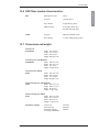
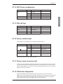
1.2.7 Dimensions and weight
Control Unit
6301/02/03: Width: 241 mm (9.5")
Height: 107 mm (4.2")
Depth: 99 mm (3.9")
Weight: 0.82 kg (1.8 lbs)
Transceiver Unit 150 W/250 W
6365/66/68: Width: 390 mm (15.3")
Height: 445 mm (17.5")
Depth: 127 mm (5")
Weight: 19 kg (41.9 lbs)
Transceiver Unit 500 W
6369: Width: 392 mm (15.4")
Height: 507 mm (20")
Depth: 217 mm (8.5")
Weight: 28 kg (61.7 lbs)
Antenna Tuning Unit 150 W/250 W
6384: Width: 290 mm (11.4")
Height: 500 mm (19.7")
Depth: 80 mm (3.1")
Weight: 3.3 kg (7.3 lbs)
Antenna Tuning Unit 500 W
6383: Width: 401 mm (15.8")
Height: 617 mm (24.3")
Depth: 356 mm (14")
Weight: 17 kg (37.5 lbs)
Equipment category: Control Unit: Protected
Transceiver Unit: Protected
Antenna Tuning Unit: Exposed
(According to IEC60940)

1-6
Chapter 1: General information 98-144591-D
Technical data

2-1
Installation
Chapter 2: Installation
98-144591-D
Mounting the Units
Installation
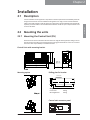
2.1 Description
Correct installation of the equipment is important for maximum performance and reliability. Antennas
and ground connections must be installed with the greatest care using corrosion resistant materials.
Cable routing shall be made so that the cables are protected from physical damage. Sharp cable bends
especially on coaxial cables must be avoided and a suffi cient number of clips or straps should be used
to secure the cables.
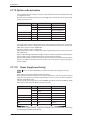
2.2 Mounting the units
2.2.1 Mounting the Control Unit (CU)
One Control Unit can be connected to the Transceiver Unit using the cable supplied (CU-TU Bus). The CU
may be mounted up to 100 m from the Transceiver Unit using just a multicable 5 x 2 x 0.5 mm
2
screened.
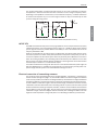
The Control Unit may be tabletop or bulkhead mounted.
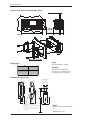
Control Units with mounting bracket
Mounting option Drilling plan for bracket
Chapter 2
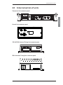
Control unit connector panel
Weight:
Control Unit 0.82 kg
Mounting Bracket 0.20 kg
200mm
53mm
71mm
247mm
9mm
4 x M4 or hole for
self-tapping ø3.9
23.5mm

2-2
Chapter 2: Installation
98-144591-D
Mounting the Units
Control Units with fl ush mounting bracket
Drilling plan
Flush mount template
Remove material from shaded area only!
89mm
227mm
R2.5mm x 4
Weight:
Flush mount bracket 0.04 kg
WARNING:
Only use screws supplied with
mounting kit for attaching fl ush
mounting bracket to Control Unit.
Handset for Control Unit
This Handset has a hook-on/off function,
which is activated by a small magnet embedded
in the cradle.
The cradle must be installed as illustrated in
order to ensure the hook-on/off functionality
of the Handset.
75
62
226
* 120
min. 100
Space for handset access
Space for cable and handset cable
54
45
135
39655C
Drilling plan
Weight:
Handset for Control Unit 0.4 kg (0.02
lbs)
Dimensions are in mm

2-3
Installation
Chapter 2: Installation
98-144591-D
Mounting the Units
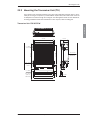
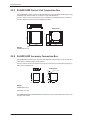
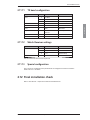
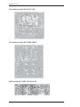
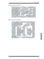
2.2.2 Mounting the Transceiver Unit (TU)
The Transceiver Unit should be installed in a dry place and consideration should be given to acces-
sibility for servicing. It is important to provide suffi cient airspace below, above and in front of the unit
for adequate air circulation through the cooling fi ns. The drawing below shows the outer dimensions,
mounting possibilities and the minimum distance to other objects, as well as a drilling plan.
Transceiver Unit 150 W/250 W
105 mm 350 mm
360 mm
391 mm
35 mm
150 mmMin.
379 mm
150 mmMin.
360 mm
Space for
cable access
Space for
service
4 x ø8mm
443 mm
4 x ø6mm
23.5 mm
88 mm
145 mm
500Min. mm
Space for airflow
and service

2-4
Chapter 2: Installation
98-144591-D
Mounting the Units
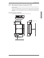
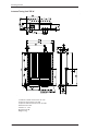
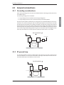
Transceiver Unit 500 W
360 mm
379 mm
35 mm 105 mm 350 mm
150 mmMin.
200 mmMin.
360 mm
391 mm
332 mm
505 mm
Space for cable
and airflow
Space for
service access
Cable fitting
4 x ø8mm
4 x ø6mm
1000Min. mm
160 mm
217 mm
23.5 mm
Space for airflow
and service
Page is loading ...
Page is loading ...
Page is loading ...
Page is loading ...
Page is loading ...
Page is loading ...
Page is loading ...
Page is loading ...
Page is loading ...
Page is loading ...
Page is loading ...
Page is loading ...
Page is loading ...
Page is loading ...
Page is loading ...
Page is loading ...
Page is loading ...
Page is loading ...
Page is loading ...
Page is loading ...
Page is loading ...
Page is loading ...
Page is loading ...
Page is loading ...
Page is loading ...
Page is loading ...
Page is loading ...
Page is loading ...
Page is loading ...
Page is loading ...
Page is loading ...
Page is loading ...
Page is loading ...
Page is loading ...
Page is loading ...
Page is loading ...
Page is loading ...
Page is loading ...
Page is loading ...
Page is loading ...
Page is loading ...
Page is loading ...
Page is loading ...
Page is loading ...
Page is loading ...
Page is loading ...
Page is loading ...
Page is loading ...
Page is loading ...
Page is loading ...
Page is loading ...
Page is loading ...
Page is loading ...
Page is loading ...
Page is loading ...
Page is loading ...
-
 1
1
-
 2
2
-
 3
3
-
 4
4
-
 5
5
-
 6
6
-
 7
7
-
 8
8
-
 9
9
-
 10
10
-
 11
11
-
 12
12
-
 13
13
-
 14
14
-
 15
15
-
 16
16
-
 17
17
-
 18
18
-
 19
19
-
 20
20
-
 21
21
-
 22
22
-
 23
23
-
 24
24
-
 25
25
-
 26
26
-
 27
27
-
 28
28
-
 29
29
-
 30
30
-
 31
31
-
 32
32
-
 33
33
-
 34
34
-
 35
35
-
 36
36
-
 37
37
-
 38
38
-
 39
39
-
 40
40
-
 41
41
-
 42
42
-
 43
43
-
 44
44
-
 45
45
-
 46
46
-
 47
47
-
 48
48
-
 49
49
-
 50
50
-
 51
51
-
 52
52
-
 53
53
-
 54
54
-
 55
55
-
 56
56
-
 57
57
-
 58
58
-
 59
59
-
 60
60
-
 61
61
-
 62
62
-
 63
63
-
 64
64
-
 65
65
-
 66
66
-
 67
67
-
 68
68
-
 69
69
-
 70
70
-
 71
71
-
 72
72
-
 73
73
-
 74
74
-
 75
75
-
 76
76


COBHAM SAILOR 6000B Installation guide
- Type
- Installation guide
- This manual is also suitable for
Ask a question and I''ll find the answer in the document
Finding information in a document is now easier with AI
Related papers
-
COBHAM SAILOR 6081 Installation guide
-
-
-
-
-
-
-
-
-
Other documents
-
MIGRO 943300 Series User manual
-
 ELECTRO DÉPÔT 94334 Series User manual
-
Thrane & Thrane A/S ROJ6300 User manual
-
-
Motorola F2265A Owner's manual
-
Metra Symfony ExceptionMaximum execution time of 30 seconds exceededJP-JKWIP Operating instructions
-
Sailor HC4500 Operating instructions
-
-
-
