Page is loading ...

Duodos 50, 100, PPS/PVT/PT
Air-driven double diaphragm pump
Assembly and operating instructions
A2740
EN
Original operating instructions (2006/42/EC)Part number 981451 BA DUO 016 06/20 EN
Please carefully read these operating instructions before use. · Do not discard.
The operator shall be liable for any damage caused by installation or operating errors.
The latest version of the operating instructions are available on our homepage.

In order to make it easier to read, this document uses the male
form in grammatical structures but with an implied neutral sense.
The document is always aimed equally at women, men and
gender-neutral persons. We kindly ask readers for their under‐
standing in this simplification of the text.
Please read the supplementary information in its entirety.
Information
This provides important information relating to the
correct operation of the unit or is intended to make
your work easier.
Warning information
Warning information includes detailed descriptions of the haz‐
ardous situation, see
Ä Chapter 2.1 ‘Labelling of Warning Informa‐
tion’ on page 5
.
The following symbols are used to highlight instructions, links, lists,
results and other elements in this document:
Tab. 1: More symbols
Symbol Description
Action, step by step.
⇨ Outcome of an action.
Links to elements or sections of these instructions or other applicable documents.
n
List without set order.
[Button]
Display element (e.g. indicators).
Operating element (e.g. button, switch).
‘Display/GUI’
Screen elements (e.g. buttons, assignment of function keys).
CODE
Presentation of software elements and/or texts.
General non-discriminatory approach
Supplementary information
Supplemental directives
2

Table of contents
1 Function and identification.................................................... 4
1.1 Function........................................................................ 4
1.2 Identification.................................................................. 4
2 Safety and responsibility....................................................... 5
2.1 Labelling of Warning Information.................................. 5
2.2 User qualification.......................................................... 7
2.3 Intended use................................................................. 8
2.4 Duodos general safety notes........................................ 8
3 Transport and storage......................................................... 11
3.1 Transport.................................................................... 11
3.2 Storage....................................................................... 11
4 Assembly............................................................................ 12
4.1 Installation environment.............................................. 12
4.1.1 Securing the double diaphragm pump..................... 14
4.2 Ambient conditions..................................................... 14
4.3 Design of the suction side........................................... 14
4.4 Compressed air supply............................................... 15
5 Checking tightening torque prior to commissioning............ 16
6 Operation of the double diaphragm pump.......................... 17
7 Commissioning................................................................... 18
7.1 Checks prior to commissioning................................... 18
7.2 Priming........................................................................ 19
7.3 Interrupting operation.................................................. 19
8 Maintenance of the double diaphragm pump...................... 20
8.1 Troubleshooting.......................................................... 20
8.2 Maintenance of the diaphragm................................... 23
8.3 Maintenance of the slide rod....................................... 25
8.4 Maintenance of the ball valves................................... 26
9 Disposal of used parts........................................................ 28
10 Technical drawing............................................................... 29
10.1 Exploded drawings and parts lists for Duodos 50..... 30
10.2 Exploded drawings and parts lists for Duodos 100... 32
11 Technical data..................................................................... 34
11.1 Performance curves.................................................. 35
12 Declaration of Conformity................................................... 37
13 Index................................................................................... 38
Table of contents
3

1 Function and identification
1.1 Function
The Duodos is an air-driven double diaphragm pump.
The Duodos is run-dry safe and self-priming.
The pump capacity of the double diaphragm pump can be con‐
trolled by changing the pressure in the air supply. The air control is
designed for oil-free operation. The Duodos is ideally suited for the
transport of liquid chemicals.
The Duodos double diaphragm pump transports liquids up to a
delivery height of 7 m. As the pump capacity depends greatly on
the back pressure, always observe the performance curve.
Check the compatibility of the material when selecting the double
diaphragm pump. Also consider the density, viscosity, solids con‐
tent and temperature of the liquid being pumped.
Permissible values for the medium
Temperature of the medium
–
PP version: 10 ... 80 °C
–
PVDF version: -13 ... 93 °C
Viscosity of the medium: max. 200 mPas
Solids: < 3 mm
1.2 Identification
Type Housing Diaphragm Pump capacity in l/min Order number
50 PPS PP
Santoprene
®
0 ... 50 1103384
50 PVT PVDF
Teflon
®
0 ... 50 1103382
50 PT PP
Teflon
®
0 ... 50 On request
100 PPS PP
Santoprene
®
0 ... 100 1103383
100 PVT PVDF
Teflon
®
0 ... 100 1103380
Function and identification
4

2 Safety and responsibility
2.1 Labelling of Warning Information
These operating instructions provide information on the technical
data and functions of the product. These operating instructions pro‐
vide detailed warning information and are provided as clear step-
by-step instructions.
The warning information and notes are categorised according to
the following scheme. A number of different symbols are used to
denote different situations. The symbols shown here serve only as
examples.
DANGER!
Nature and source of the danger
Consequence: Fatal or very serious injuries.
Measure to be taken to avoid this danger.
Description of hazard
– Denotes an immediate threatening danger. If
the situation is disregarded, it will result in fatal
or very serious injuries.
WARNING!
Nature and source of the danger
Possible consequence: Fatal or very serious inju‐
ries.
Measure to be taken to avoid this danger.
– Denotes a possibly hazardous situation. If the
situation is disregarded, it could result in fatal
or very serious injuries.
CAUTION!
Nature and source of the danger
Possible consequence: Slight or minor injuries.
Material damage.
Measure to be taken to avoid this danger.
– Denotes a possibly hazardous situation. If the
situation is disregarded, it could result in slight
or minor injuries. May also be used as a
warning about material damage.
NOTICE!
Nature and source of the danger
Damage to the product or its surroundings.
Measure to be taken to avoid this danger.
– Denotes a possibly damaging situation. If the
situation is disregarded, the product or an
object in its vicinity could be damaged.
Introduction
Safety and responsibility
5

Type of information
Hints on use and additional information.
Source of the information. Additional measures.
–
Denotes hints on use and other useful informa‐
tion. It does not indicate a hazardous or dam‐
aging situation.
Safety and responsibility
6

2.2 User qualification
WARNING!
Danger of injury with inadequately qualified per‐
sonnel
The operator of the system / equipment is respon‐
sible for ensuring that the qualifications are ful‐
filled.
If inadequately qualified personnel work on the unit
or loiter in the hazard zone of the unit, this could
result in dangers that could cause serious injuries
and material damage.
– All work on the unit should therefore only be
conducted by qualified personnel.
– Unqualified personnel should be kept away
from the hazard zone.
The pertinent accident prevention regulations, as
well as all other generally acknowledged safety
regulations, must be adhered to.
Training Definition
Instructed personnel An instructed person is deemed to be a person who has been instructed and,
if required, trained in the tasks assigned to him and possible dangers that
could result from improper behaviour, as well as having been instructed in the
required protective equipment and protective measures.
Trained user A trained user is a person who fulfils the requirements made of an instructed
person and who has also received additional training specific to the system
from the manufacturer or another authorised distribution partner.
Trained, qualified per‐
sonnel
A trained, qualified employee is deemed to be a person who is able to assess
the tasks assigned to him and recognize possible hazards based on his
training, knowledge and experience, as well as knowledge of pertinent regula‐
tions. A trained, qualified employee must be able to perform the tasks
assigned to him independently with the assistance of drawing documentation
and parts lists. The assessment of a person's technical training can also be
based on several years of work in the relevant field.
Electrical technician An electrical technician is able to complete work on electrical systems and rec‐
ognise and avoid possible dangers independently based on his technical
training and experience as well as knowledge of pertinent standards and regu‐
lations. An electrical technician must be able to perform the tasks assigned to
him independently with the assistance of drawing documentation, parts lists,
terminal and circuit diagrams. The electrical technician must be specifically
trained for the working environment in which the electrical technician is
employed and be conversant with the relevant standards and regulations.
Service The Service department refers to service technicians, who have received
proven training and have been authorised by the manufacturer to work on the
system.
Safety and responsibility
7

2.3 Intended use
CAUTION!
Intended use
Possible consequences if the instructions are not
observed: Minor injuries and material damage
– The pump is intended for liquids transport
– The pump is not intended for the transport of
gaseous or solid media
– Only use the pump in accordance with the
technical data and specifications outlined in the
operating instructions.
– The pump is not designed for use in areas at
risk from explosion
– Only switch the device on if it has been prop‐
erly fastened to the ground or its holding fix‐
ture.
2.4 Duodos general safety notes
WARNING!
Danger from hazardous substances!
Possible consequence: Fatal or very serious inju‐
ries.
Please ensure when handling hazardous sub‐
stances that you have read the latest safety data
sheets provided by the manufacture of the haz‐
ardous substance. The actions required are
described in the safety data sheet. Check the
safety data sheet regularly and replace, if neces‐
sary, as the hazard potential of a substance can be
re-evaluated at any time based on new findings.
The system operator is responsible for ensuring
that these safety data sheets are available and that
they are kept up to date, as well as for producing
an associated hazard assessment for the worksta‐
tions affected.
Safety and responsibility
8

WARNING!
Hazardous media / contamination of persons and
equipment
Possible consequence: Fatal or very serious inju‐
ries. material damage
– Ensure the device is resistant to the media
being conveyed
– Always observe the safety data sheets for the
media to be conveyed. The system operator
must ensure that these safety data sheets are
available and that they are kept up-to-date
– The safety data sheets for the media being
conveyed are always decisive for initiating
counter measures in the event of leakage to
the media being conveyed
– Observe the general restrictions in relation to
viscosity limits, chemical resistance and den‐
sity
WARNING!
Service life of the diaphragm
Possible consequence: Fatal or very serious inju‐
ries
The service life of the diaphragm cannot be pre‐
cisely specified. For this reason, the possibility of
fracture and subsequent leakage of liquids must be
taken into account.
In addition, you must prevent particles from the
defective diaphragm reaching the media being
conveyed. This can be achieved e.g. by filtration, a
hose rupture alarm or other means suitable for the
respective process.
CAUTION!
Compressed air
Before working on the double diaphragm pump,
close the compressed air lines and vent the double
diaphragm pump.
Before undertaking any maintenance and repair
work, close off the compressed air supply, dis‐
charge the compressed air and detach the air
supply line from the double diaphragm pump. The
line to the discharge side of the double diaphragm
pump may be under pressure and must likewise be
vented.
CAUTION!
Hot surface
When conveying hot liquids, the pump can likewise
become hot. Hot surfaces may then be present on
the pump. Bear this in mind and take suitable
measures to reduce any hazards.
Safety and responsibility
9

Maximum pump sound pressure level 91 dB
Depending on the operating conditions, the max‐
imum sound pressure level of the device can reach
88 dB ± 3 dB. Bear this in mind and take suitable
measures to reduce any impact caused by this
sound pressure level. The type and implementa‐
tion of suitable measures depends on the local cir‐
cumstances and is the responsibility of the system
operator.
Check the fastening elements are correctly seated.
Before commissioning the double diaphragm
pump, you must check that all fastening elements
with sealing rings are correctly seated. The seals
may ‘creep’ , so that the fastening elements come
loose over time.
In the event of a diaphragm rupture
In the event of a diaphragm rupture, the pumped
medium can enter the air system of the double dia‐
phragm pump and from there into the atmosphere.
If the pumped medium is a dangerous, harmful or
toxic substance, the air outlet must be routed to a
suitable area where safe disposal is possible.
Operation in the open air and outdoors
–
Take suitable measures to protect the device
from environmental influences when operating
outside such as:
–
UV rays
–
Humidity
–
Frost, etc.
Safety and responsibility
10

3 Transport and storage
n User qualification, transport and storage: trained user, see
Ä Chapter 2.2 ‘User qualification’ on page 7
WARNING!
Danger from hazardous substances!
Possible consequence: Fatal or very serious inju‐
ries.
Please ensure when handling hazardous sub‐
stances that you have read the latest safety data
sheets provided by the manufacture of the haz‐
ardous substance. The actions required are
described in the safety data sheet. Check the
safety data sheet regularly and replace, if neces‐
sary, as the hazard potential of a substance can be
re-evaluated at any time based on new findings.
The system operator is responsible for ensuring
that these safety data sheets are available and that
they are kept up to date, as well as for producing
an associated hazard assessment for the worksta‐
tions affected.
3.1 Transport
Transport
n The pump is protected by means of cardboard packaging
n The packaging materials can be recycled
n Consider the ambient conditions
3.2 Storage
The device must be completely drained before storage.
Tab. 2: Permissible storage conditions:
All versions: + 5 °C ... 60 °C
All versions: < 95% relative air humidity (non-condensing)
Tab. 3: Permissible operating conditions:
All versions: - 10 °C ... 40 °C
All versions: < 95% relative air humidity (non-condensing)
Transport and storage
11

4 Assembly
n User qualification, installation: trained and qualified personnel
Ä Chapter 2.2 ‘User qualification’ on page 7
CAUTION!
Possible consequence: Slight or minor injuries.
Material damage.
Observe the permissible ambient conditions.
4.1 Installation environment
Upright installation
Install the double diaphragm pump upright and
plumb. The valves of the double diaphragm pump
operate when loaded by gravity. The valve balls
are pressed by gravity into the valve seat and then
seal it off. Installation outside the vertical axis
impairs the function of the valves.
Nominal width of the pipework
The threaded connectors must not reduce the
nominal width of the pipework or the double dia‐
phragm pump. The hydraulic connectors have
internal and external threads. Do not screw
threaded fittings on to the internal thread as this
would lead to a reduction of the nominal width.
Keep the suction line short and the number of pipe fittings minimal.
Do not reduce the diameter of the suction line. If a rigid pipework
system is used, insert short flexible sections of hose between the
double diaphragm pump and pipework to protect the double dia‐
phragm pump against vibration and tensile and compressive
forces. The installation of a pulsation damper is recommended to
reduce pulsation in the medium being pumped.
Assembly
12

max. 7 bar
Compressed air remote outlet
Optional
Optional
Optional
Liquid
inlet
Outlet of
drainage valve
Compressed air
Compressed air remote outlet
A2739
Fig. 1: Recommended installation with a compressed air remote outlet as an option
Connect a hose to the new outlet opening and install the silencer
on the end of the hose. Use a hose with the same diameter as the
diameter of the outlet opening 3/8” NPT.
An optional kit is needed for the compressed air remote outlet.
1. Uncover the compressed air outlet opening of the pump.
Use a hose with the same diameter as the diam‐
eter of the outlet opening.
2. Connect a hose to the new outlet opening.
3. Install the silencer at the end of the hose.
4. Position the end of the hose with the silencer at a suitable
place, e.g. in a protective casing.
Compressed air remote outlet with
silencer
Assembly
13

4.1.1 Securing the double diaphragm pump
Correct securing of the device
Only switch the device on if it has been properly
fastened to the ground or its holding fixture. The
system operator is responsible for ensuring that
the ground and the fittings can hold the device
safely and under all operating conditions.
4.2 Ambient conditions
NOTICE!
Ambient conditions
Possible consequence: Property damage and
increased wear and tear
Assembly is to be carried out in the following order.
If the pump has to be installed outdoors, then it is
to be equipped with protection against sunlight and
weather influences.
When positioning the pump, ensure that sufficient
room for access is provided for all types of mainte‐
nance work.
4.3 Design of the suction side
Nominal width of the pipework
Make sure that the threaded connectors do not
reduce the nominal width of the pipework or the
double diaphragm pump.
Dimensioning of the suction side
Design the suction side to be generously sized.
Ensure that the supply to the double diaphragm
pump with the liquid to be pumped is ensured
under all load and operating statuses. Ensure that
the inside diameters of the suction lines are gener‐
ously sized.
Install the double diaphragm pump as close as possible to the
medium to be pumped to ensure a maximum service life of the dia‐
phragm. The minimum air pressure to operate the double dia‐
phragm pump is approximately 1.5 bar.
Assembly
14

4.4 Compressed air supply
Compressed air supply
Connect the double diaphragm pump to a com‐
pressed air supply in accordance with the current
state of the art (ISO 8573-1). We require unoiled,
residual oil-free (residual oil from the compressors
of maximum 0.1 mg/m³ for HEES-liquids, bio-oils
or max. 5 mg/ m³ permitted for mineral oils) and
appropriately dried compressed air (ISO 8573-1,
class 4 with 3 °C PDP).
Our recommendation is that the pressure dew
point must be at least 10 °C below the ambient
temperature.
Suitable compressed air supply
The system operator is responsible for the provi‐
sion of a suitable compressed air supply. When
doing so, observe ISO 8573.
Design the compressed air supply to have generous dimensions.
Your compressed air supply must be capable of supplying the
double diaphragm pump with sufficient compressed air at any time
and under all operating statuses. In this respect also consider the
air consumption of other devices and machinery connected to the
same compressed air supply. Considerable pressure fluctuations
can occur in the compressed air supply when switching com‐
pressed air consumers on and off.
Do not allow the air pressure of the supplied air to exceed 7 bar
(100 psi). Connect the air inlet of the double diaphragm pump to a
compressed air supply, which is designed to provide the required
pump capacity in terms of air volume and pressure. Connect a con‐
trol valve upstream of the double diaphragm pump to guarantee
the supply pressure remains within the specified values.
If there is a rigid air supply line, insert a short section of flexible
hose between the double diaphragm pump and the pipework.
Make sure that the weight of the air supply line, control valve, and
filters does not weigh down on the air connection fitting of the
double diaphragm pump, instead support it in a suitable manner.
Otherwise the double diaphragm pump can be damaged.
Due to their design, the air valve and the pilot valve do not require
any lubrication and must also not be lubricated.
Water in the compressed air can lead to the exhaust air freezing or
the double diaphragm pump icing up. Possible consequences
include malfunctions or failure of the double diaphragm pump. We
recommend fitting an air dryer. The air dryer extracts the water
from the compressed air and protects it from icing up.
Lubrication of the air valves
Moisture in the air line
Assembly
15

5 Checking tightening torque prior to commissioning
Lasting tightness
Check that the threaded connectors have the cor‐
rect torque during commissioning.
We also recommend checking these threaded con‐
nectors for correct torque at least once a year
because the pump material yields and the tight‐
ening torque is then reduced.
6
4
2
1
3
5
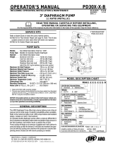
A2741
Fig. 2: Check the tightening torque prior to commissioning, in the
sequence shown in
Fig. 2
.
Check the tightening torque of screws 1 ... 6 before commis‐
sioning. Tighten all screws to 5 Nm (Duodos 50) or 15 Nm
(Duodos 100) in the sequence shown in Fig. 2.
Checking tightening torque prior to commissioning
16

6 Operation of the double diaphragm pump
n User qualification: operation instructed personnel, see
Ä Chapter 2.2 ‘User qualification’ on page 7
The double diaphragm pump is fully integrated into the customer
provided system and is then controlled from this system. It is not
possible to operate the double diaphragm pump directly.
Operation of the double diaphragm pump
17

7 Commissioning
n User qualification, commissioning: trained user, see
Ä Chapter
2.2 ‘User qualification’ on page 7
Check the fastening elements are correctly seated.
Before commissioning the double diaphragm
pump, you must check that all fastening elements
with sealing rings are correctly seated. The seals
may ‘creep’ , so that the fastening elements come
loose over time.
7.1 Checks prior to commissioning
WARNING!
Danger from hazardous substances!
Possible consequence: Fatal or very serious inju‐
ries.
Please ensure when handling hazardous sub‐
stances that you have read the latest safety data
sheets provided by the manufacture of the haz‐
ardous substance. The actions required are
described in the safety data sheet. Check the
safety data sheet regularly and replace, if neces‐
sary, as the hazard potential of a substance can be
re-evaluated at any time based on new findings.
The system operator is responsible for ensuring
that these safety data sheets are available and that
they are kept up to date, as well as for producing
an associated hazard assessment for the worksta‐
tions affected.
The following checks are to be carried out:
n Ensure that the device has not been damaged during transpor‐
tation or storage. Immediately report any damage to the sup‐
plier
n Check that the air pressure is suitable for the device.
n Ensure that the device is suitable for the liquid to be conveyed
and that it will not be attacked.
n Make sure that the temperature of the liquid does not exceed
the recommended temperature range
n Install a manometer in the discharge line if the back pressure
value is unknown
n Under the operating conditions, check the values for flow, pres‐
sure, etc.
n Install a pressure relief valve in the discharge line in order to
protect the pump in the event that a valve is unintentionally
closed off or the line is blocked in another way.
Commissioning
18

7.2 Priming
1. To start the double diaphragm pump, open the air value by
approximately 1/2 to 3/4 of a turn
2.
Cavitation
If opening of the air valve causes the stroke
rate of the double diaphragm pump to
increase, but not however the flow volume
passing through the double diaphragm pump,
then cavitation is the cause. Slightly turn
back the air valve so that the air consumption
and feed rate of the double diaphragm pump
are set in an optimum ratio.
Once the double diaphragm pump is filled with water, open
the air valve further to set the required air flow.
7.3 Interrupting operation
WARNING!
Danger from hazardous substances!
Possible consequence: Fatal or very serious inju‐
ries.
Please ensure when handling hazardous sub‐
stances that you have read the latest safety data
sheets provided by the manufacture of the haz‐
ardous substance. The actions required are
described in the safety data sheet. Check the
safety data sheet regularly and replace, if neces‐
sary, as the hazard potential of a substance can be
re-evaluated at any time based on new findings.
The system operator is responsible for ensuring
that these safety data sheets are available and that
they are kept up to date, as well as for producing
an associated hazard assessment for the worksta‐
tions affected.
Rinse through the double diaphragm pump after every use if liquids
are used which when stationary have a tendency to form deposits
or to solidify. This avoids damage to the double diaphragm pump.
Liquid residues remaining in the double diaphragm pump may dry
out and form deposits. When restarting the double diaphragm
pump, this can lead to problems at the diaphragms and the ball
valves. At temperatures below 0 °C the double diaphragm pump
must always be completely drained.
Commissioning
19

8 Maintenance of the double diaphragm pump
n User qualification, maintenance: instructed persons
Ä Chapter
2.2 ‘User qualification’ on page 7
WARNING!
Danger from hazardous substances!
Possible consequence: Fatal or very serious inju‐
ries.
Please ensure when handling hazardous sub‐
stances that you have read the latest safety data
sheets provided by the manufacture of the haz‐
ardous substance. The actions required are
described in the safety data sheet. Check the
safety data sheet regularly and replace, if neces‐
sary, as the hazard potential of a substance can be
re-evaluated at any time based on new findings.
The system operator is responsible for ensuring
that these safety data sheets are available and that
they are kept up to date, as well as for producing
an associated hazard assessment for the worksta‐
tions affected.
Before all work
Before all work on the double diaphragm pump,
disconnect the double diaphragm pump from the
compressed air supply and the feed and discharge
lines, vent and decontaminate. Always observe the
safety data sheet for the chemicals to be con‐
veyed.
8.1 Troubleshooting
The pump is not working.
Cause: Recommended measure:
The outlet valve on the discharge side is not
open.
Open the discharge valve on the discharge side.
No air supply. Switch on the compressor and open the air valve and the
air regulator.
The air pressure is too low. Check the compressor and the configuration of the air
line.
Air is escaping from the connecting elements. Check the connecting elements and the torque of the
screws.
The air lines or additional equipment are
blocked with foreign bodies.
Check and clean the air line.
The outlet opening (silencer) of the pump is
blocked with foreign bodies.
Check and clean the outlet opening and the silencer.
The liquid line is blocked with foreign bodies. Check and clean the liquid line.
The pump is blocked with foreign bodies. Remove, check and clean the pump housing.
Maintenance of the double diaphragm pump
20
/