Page is loading ...

E2001 D PRINTED IN U.S.A.
&
(419) 636-4242
D
F
AX (419) 633-1674
INGERSOLL-RAND COMPANY
P.O. BOX 151 D ONE ARO CENTER D BRYAN, OHIO 43506Ć0151
OPERATOR’S
MANUAL
PD30X-X-B
RELEASED: 8-14-98
REVISED: 3-7-01
(REV.
J)
INCLUDING: OPERATION, INSTALLATION & MAINTENANCE
3”
DIAPHRAGM PUMP
1:1
RA
TIO (METALLIC)
READ THIS MANUAL CAREFULL
Y BEFORE INST
ALLING,
OPERA
TING OR SER
VICING THIS EQUIPMENT
.
It
is the responsibility of the employer to place this information in the hands of the operator
. Keep for future reference.
SERVICE KITS
Refer to Model Chart to match the pump material options.
637303ĆXX for Fluid Section Repair (see page 4). Note: This kit also
contains several air motor seals which will need to be replaced.
637302 for Air Section Repair (see page 6).
PUMP
DA
TA
Models See Model Description Chart for ĆXXX"....
Pump Type Metallic Air Operated Double Diaphragm
Material See Model Description Chart....
Weight Aluminum (wet end) 113 lbs (51.3 kgs).... ......
Cast Iron (wet end) 197 lbs (89.4 kgs)......
Hastelloy (wet end) 203 lbs (92.1 kgs)......
Stainless Steel (wet end) 203 lbs (92.1 kgs)..
(add 40 lbs [18.1 kg] for stainless steel air motor section)
Maximum Air Inlet Pressure 120 p.s.i.g. (8.3 bar).........
Maximum Material Inlet Pressure 10 p.s.i.g. (.69 bar).....
Maximum Outlet Pressure 120 p.s.i.g. (8.3 bar)...........
Maximum Flow Rate (flooded inlet) 275 g.p.m. (1041 l.p.m.)......
Displacement / Cycle @ 100 p.s.i.g. 2.8 gal. (10.6 lit.)...
Maximum Particle Size 3/8" dia. (9.5 mm).............
Maximum Temperature Limits 200_F (93_C)........
Dimensional Data see page 8.................
Mounting Dimensions 10Ć5/32" x 12Ć1/16" (258 mm x 306 mm)..
Noise Level @ 70 p.s.i., 50 c.p.m.À 83.0 db(A)Á....
À Tested with 67263 muffler assembly installed.
Á The pump sound pressure levels published here have been updated to an Equivalent
Continuous Sound Level (L
Aeq
) to meet the intent of ANSI S1.13Ć1971, CAGIĆPNEUĆ
ROP S5.1 using four microphone locations.
NOTICE:All possible options are shown in the chart however certain comĆ
binations may not be recommended, consult a representative or the factoĆ
ry if you have questions concerning availability.
GENERAL
DESCRIPTION
The ARO Diaphragm Pump offers high volume delivery even at low air
pressure and a broad range of material compatibility options available.
Refer to the model and option chart. ARO pumps feature stall resistant
design, modular air motor / fluid sections.
Air operated double diaphragm pumps utilize a pressure differential in
the air chambers to alternately create suction and positive fluid pressure in
the fluid chambers, ball checks insure a positive flow of fluid.
Pump cycling will begin as air pressure is applied and it will continue to
pump and keep up with the demand. It will build and maintain line presĆ
sure and will stop cycling once maximum line pressure is reached (disĆ
pensing device closed) and will resume pumping as needed.
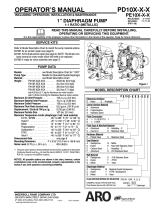
3'' DIAPHRAGM PUMP
PD30XĆXXXĆXXXĆB
D005
MODEL
DESCRIPTION CHART
PD30 X ĆX X X ĆX X X ĆB
PD30X Ć XXX Ć X X X ĆB
637303 Ć X X
DIAPHRAGMBALL
FLUID SECTION SERVICE KIT SELECTION
EXAMPLE: MODEL # PD30AĆACSĆSAAĆB
FLUID SECTION SERVICE KIT # 637303ĆAA
SEAT MATERIAL
A - SantopreneR L - Hastelloy
G - Nitrile S - 316 Stainless Steel
K - PVDF (KynarR) H - Hard 440 Stainless Steel
DIAPHRAGM MATERIAL
A - Santoprene T - Teflon
G - Nitrile V - Viton
BALL MATERIAL
A - Santoprene T - TeflonR
G - Nitrile V - VitonR
HARDWARE MATERIAL
P - Plated Steel S - Stainless Steel
FLUID CAPS & MANIFOLD MATERIAL
A - Aluminum H - Hastelloy
C - Cast Iron S - Stainless Steel
THREAD
A - N.P.T.F. B - BSP
CENTER SECTION MATERIAL
A - Aluminum S - Stainless Steel

PD30XĆXĆBPAGE 2 OF 8
OPERATING
AND SAFETY PRECAUTIONS
READ, UNDERSTAND, AND FOLLOW THIS INFORMATION TO AVOID INJURY AND PROPERTY DAMAGE.
EXCESSIVE AIR PRESSURE
STATIC SPARK
HAZARDOUS MATERIALS
HAZARDOUS PRESSURE
WARNING
EXCESSIVE AIR PRESSURE. Can cause personĆ
al injury, pump damage or property damage.
S Do not exceed the maximum inlet air pressure as stated on the
pump model plate.
S Be sure material hoses and other components are able to withĆ
stand fluid pressures developed by this pump. Check all
hoses for damage or wear. Be certain dispensing device is
clean and in proper working condition.
WARNING STATIC SPARK. Can cause explosion resulting
in severe injury or death. Ground pump and pumping system.
S Use the pump grounding screw terminal provided. Use Aro
Part No. 66885Ć1 Ground Kit or connect a suitable ground wire
(12 ga. min.) to a good earth ground source.
S Secure pump, connections and all contact points to avoid
vibration and generation of contact or static spark.
S Consult local building codes and electrical codes for specific
grounding requirements.
S After grounding, periodically verify continuity of electrical
path to ground. Test with an ohmmeter from each component
(e.g., hoses, pump, clamps, container, spray gun, etc.) to
ground to insure continuity. Ohmmeter should show 100
ohms or less.
S Submerse the outlet hose end, dispensing valve or device in
the material being dispensed if possible. (Avoid free streamĆ
ing of material being dispensed.)
S Use hoses incorporating a static wire.
S Use proper ventilation.
S Keep inflammables away from heat, open flames and sparks.
S Keep containers closed when not in use.
WARNING Pump exhaust may contain contaminants. Can
cause severe injury. Pipe exhaust away from work area and
personnel.
S In the event of a diaphragm rupture material can be forced out
of the air exhaust muffler.
S Pipe the exhaust to a safe remote location when pumping hazĆ
ardous or inflammable materials.
S Use a grounded 1" min. i.d. hose between the pump and the
muffler.
WARNING
HAZARDOUS PRESSURE. Can result in serious
injury or property damage. Do not service or clean pump,
hoses or dispensing valve while the system is pressurized.
S Disconnect air supply line and relieve pressure from the sysĆ
tem by opening dispensing valve or device and / or carefully
and slowly loosening and removing outlet hose or piping from
pump.
WARNING HAZARDOUS MATERIALS. Can cause serious
injury or property damage. Do not attempt to return a pump to
the factory or service center that contains hazardous material.
Safe handling practices must comply with local and national
laws and safety code requirements.
S Obtain Material Safety Data Sheets on all materials from the
supplier for proper handling instructions.
WARNING EXPLOSION HAZARD. Models containing aluĆ
minum wetted parts cannot be used with III.ĆTrichloroethane,
Methylene Chloride or other Halogenated Hydrocarbon solĆ
vents which may react and explode.
S Check pump motor section, fluid caps, manifolds and all
wetted parts to assure compatibility before using with solĆ
vents of this type.
WARNING
MISAPPLICATION HAZARD. Do not use models
containing aluminum wetted parts with food products for huĆ
man consumption. Plated parts can contain trace amounts of
lead.
CAUTION Verify the chemical compatibility of the pump
wetted parts and the substance being pumped, flushed or reĆ
circulated. Chemical compatibility may change with temperaĆ
ture and concentration of the chemical(s) within the
substances being pumped, flushed or circulated. For specific
fluid compatibility, consult the chemical manufacturer.
CAUTION Maximum temperatures are based on mechaniĆ
cal stress only. Certain chemicals will significantly reduce
maximum safe operating temperature. Consult the chemical
manufacturer for chemical compatibility and temperature limĆ
its. Refer to PUMP DATA on page 1 of this manual.
CAUTION Be certain all operators of this equipment have
been trained for safe working practices, understand it's limitaĆ
tions, and wear safety goggles / equipment when required.
CAUTION
Do not use the pump for the structural support of
the piping system. Be certain the system components are
properly supported to prevent stress on the pump parts.
S Suction and discharge connections should be flexible conĆ
nections (such as hose), not rigid piped, and should be comĆ
patible with the substance being pumped.
CAUTION Prevent unnecessary damage to the pump. Do
not allow pump to operate when out of material for long periĆ
ods of time.
S Disconnect air line from pump when system sits idle for long
periods of time.
CAUTION
Use only genuine ARO replacement parts to asĆ
sure compatible pressure rating and longest service life.
WARNING
CAUTION
NOTICE
= Hazards or unsafe practices which could
result in severe personal injury, death or
substantial property damage.
= Hazards or unsafe practices which could
result in minor personal injury, product or
property damage.
= Important installation, operation or
maintenance information.

PAGE 3 OF 8PD30XĆXĆB
AIR
AND LUBE REQUIREMENTS
WARNING EXCESSIVE AIR PRESSURE. Can cause pump
damage, personal injury or property damage.
S A filter capable of filtering out particles larger than 50 microns
should be used on the air supply. There is no lubrication required
other than the O" ring lubricant which is applied during assembly or
repair.
S If lubricated air is present, make sure that it is compatible with the
Nitrile ``O" rings in the air motor section of the pump.
OPERATING INSTRUCTIONS
S Always flush the pump with a solvent compatible with the material
being pumped if the material being pumped is subject to setting
up" when not in use for a period of time.
S Disconnect the air supply from the pump if it is to be inactive for a
few hours.
S The outlet material volume is governed not only by the air supply
but also by the material supply available at the inlet. The material
supply tubing should not be too small or restrictive. Be sure not to
use hose which might collapse.
S When the diaphragm pump is used in a forcedĆfeed (flooded inlet)
situation it is recommended that a Check Valve" be installed at the
air inlet.
S Secure the diaphragm pump legs to a suitable surface to insure
against damage by vibration.
MAINTENANCE
Refer to the part views and descriptions as provided on page 4 through
7 for parts identification and Service Kit information.
S Certain ARO Smart Parts" are indicated which should be available
for fast repair and reduction of down time.
S Service kits are divided to service two separate diaphragm pump
functions: 1. AIR SECTION, 2. FLUID SECTION. The FLUID SECĆ
TION is divided further to match typical part MATERIAL OPTIONS.
MAINTENANCE (CONT’D)
S
Provide a clean work surface to protect sensitive internal moving
parts from contamination from dirt and foreign matter during serĆ
vice disassembly and reassembly.
S Keep good records of service activity and include pump in prevenĆ
tive maintenance program.
S Before disassembling empty captured material in the outlet manĆ
ifold by turning the pump upside down to drain material from the
pump.
FLUID
SECTION DISASSEMBL
Y
1. Remove top manifold(s).
2. Remove (22) balls, (19) O" rings and (21) seats.
3. Remove (15) fluid caps.
NOTE: Only Teflon diaphragm models use a primary (7) diaphragm
and a backup (8) diaphragm. Refer to the auxiliary view in figure 1.
4. Remove the (6) diaphragm washer, (7) or (7 / 8) diaphragms, (5)
backup washer and (196) cushion.
NOTE: Do not scratch or mar the surface of (1) diaphragm rod.
FLUID
SECTION REASSEMBL
Y
SERVICE NOTE: ARO PN 204214ĆT Diaphragm Assembly Tool is recĆ
ommended for use when reassembling the pump.
S Reassemble in reverse order.
S Clean and inspect all parts. Replace worn or damaged parts with
new parts as required.
S Lubricate (1) diaphragm rod and (144) U" cup with LubriplateR
FMLĆ2 Grease. (94276 grease packet is included in service kit.)
S Be certain the diaphragm assembly bottoms out on the (1) rod,
back off Teflon Diaphragm assembly far enough to align holes.
S For models with Teflon diaphragms: Item (8) Santoprene diaĆ
phragm is installed with the side marked AIR SIDE" towards the
pump center body. Install the (7) Teflon Diaphragm with the side
marked FLUID SIDE" towards the fluid cap.
S ReĆcheck torque settings after pump has been reĆstarted and run a
while.
Viton R and Teflon R are trademarks of the DuPont Company S Kynar R is a registered trademark of Penwalt Corp.
Santoprene R is a registered trademark of Monsanto Company, licensed to Advanced Elastomer Systems, L.P. S Lubriplate R is a registered trademark of Lubriplate Division (Fiske Brothers)

MATERIAL
CODE
[A] = Aluminum [K] = PVDF
[B] = Nitrile [SH] = Hard S'Steel
[C] = Carbon Steel [SP] = Santoprene
[Co] = Copper [SS] = Stainless Steel
[CI] = Cast Iron [T] = Teflon
[E] = E.P.R. [V] = Viton
[Ha] = Hastelloy Ć C
PD30XĆXĆBPAGE 4 OF 8
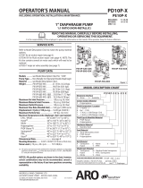
PARTS LIST / PD30X-X-B FLUID SECTION
FLUID SECTION SER
VICE KITS (637303-XX)
L KITS INCLUDE: BALLS (See Ball Option, refer to ĆXX in chart below), DIAPHRAGMS (See Diaphragm Option, refer to ĆXX in
chart below), and items; 3, 19, 70, 144, 175, 196, (listed below) plus (174) and 94276 Lubriplate FMLĆ2 grease (page 6).
SEAT OPTIONS PD30XĆXXXĆXXXĆB
21"
ĆXXX SEAT (4) [MTL] ĆXXX SEAT (4) [MTL]
ĆAXX 94104ĆA [SP] ĆKXX 94621ĆK [K]
ĆGXX 94104ĆG [B] ĆLXX 94939 [Ha]
ĆHXX 94114 [SH] ĆSXX 94113 [SS]
BALL OPTIONS PD30XĆXXXĆXXXĆB DIAPHRAGM OPTIONS PD30XĆXXXĆXXXĆB
L 22" (3.25" dia.) 19"
L SERVICE KIT L 7" / 8"
ĆXXX BALL QTY [MTL] GASKET QTY [MTL] ĆXXX
ĆXX = (Ball)
ĆXX = (Diaphragm) DIAPHRAGM (2) [MTL]
ĆXAX 94103ĆA (4) [SP] 94115 (4) [E] ĆXXA 637303ĆXA 94091ĆA [SP]
ĆXGX 94103ĆG (4) [B] Y325Ć350 (4) [B] ĆXXG 637303ĆXG 94091ĆG [B]
ĆXTX 94103ĆT (4) [T] Y328Ć350 (4) [T] ĆXXT 637303ĆXT 94090ĆT / 94110ĆA [T/SP]
ĆXVX 94103ĆV (4) [V] Y327Ć350 (4) [V] ĆXXV 637303ĆXV 95345 [V]
CENTER SECTION PART OPTIONS PD30XĆ
PD30AĆ PD30SĆ
ITEM DESCRIPTION(Size in inches) QTY PART NO. [MTL] PART NO. [MTL]
5 Backup Washer (2) 94831Ć1 [C] 94831Ć2 [SS]
68 Air Cap (1) 94030Ć1 [A] 94031Ć1 [SS]
69 Air Cap (1) 94030Ć2 [A] 94031Ć2 [SS]
126 Pipe Plug (1/4 Ć 18 N.P.T. x 7/16") (2) ----- --- Y17Ć51ĆS [SS]
L n 175 O" Ring (3/32" x d1" o.d. / f1Ć1/16" o.d.) (2) Y325Ć117 d [B] Y325Ć118 f [B]
MANIFOLD THREAD / FLUID CAP MATERIAL OPTIONS PD30XĆXXXĆ
PD30XĆXAXĆ PD30XĆXCXĆ PD30XĆXHXĆ PD30XĆXSXĆ
ITEM DESCRIPTION(Size in inches) QTY PART NO. [MTL] PART NO. [MTL] PART NO. [MTL] PART NO. [MTL]
6 Fluid Side Washer (2) 94802 [A] 94803 [SS] 94947 [Ha] 94803 [SS]
9 Washer (3/16" i.d. x 2" o.d. x 5/32") (2) Y13Ć12ĆT [SS] Y13Ć12ĆT [SS] 94949 [Ha] Y13Ć12ĆT [SS]
14 Cap Screw (3/4" Ć 16 x 3Ć1/4") (2) Y5Ć134ĆT [SS] Y5Ć134ĆT [SS] 94948 [Ha] Y5Ć134ĆT [SS]
15 Fluid Cap (2) 94024 [A] 94106 [CI] 94693 [Ha] 94107 [SS]
32 Leg (PD30AĆ) (2) ----- --- 94701Ć1 [C] N/A N/A 94703Ć1 [C]
Leg (PD30SĆ) (2) ----- --- 94701Ć2 [SS] 94703Ć2 [SS] 94703Ć2 [SS]
60 Outlet Manifold (1) 94700Ć[u] [A] 94702Ć[u] [CI] 94809Ć[u] [Ha] 94704Ć[u] [SS]
61 Inlet Manifold (1) 94699Ć[u] [A] 94305Ć[u] [CI] 94691Ć[u] [Ha] 94216Ć[u] [SS]
u For N.P.T.F. thread models (PD30XĆAXXĆXXXĆB), use Ć1"
For BSP thread models (PD30XĆBXXĆXXXĆB), use Ć2".
EXTERNAL HARDWARE OPTION PD30XĆXXXĆ
PD30XĆXXPĆ PD30XĆXXSĆ
ITEM DESCRIPTION(Size in inches) QTY PART NO. [MTL] PART NO. [MTL]
26 Screw (M12 x 1.75 Ć 6g x 45 mm) (12) 94412Ć1 [C] 94412Ć2 [SS]
27 Screw (M12x1.75Ć6gx60mm) (16) 94991Ć1 [C] 94991 [SS]
29 Nut (M12 x 1.75 Ć 6g) (16) 95053Ć1 [C] 95053 [SS]
COMMON PARTS
ITEM DESCRIPTION (Size in inches) Qty PART NO. [MTL] ITEM DESCRIPTION (Size in inches) Qty PART NO. [MTL]
1 Rod (1) 94984 [C]
L 3 O" Ring (1/8" x 1" o.d.) (2) Y328Ć210 [T]
43 Ground Lug (1) 93004 [Co]
Ln70 Gasket (2) 94100 [B]
131 Screw (M10 x 1.5 - 6g x 120 mm) (4) 94531 [C]
Ln144 U" Cup (3/16" x 1Ć3/8" o.d.) (2) Y186Ć51 [B]
n 180 Gasket (.406" i.d. x .031" thick) (4) 94098 [Co]
L 196 Cushion (2) 94631 [SP]
V Smart Parts" keep these items on hand in addition to the Service Kits for fast repair and reduction of down time.

1
15
26 ,G
FOR THE
AIR MOTOR SECTION
SEE PAGES 6 & 7
. TORQUE REQUIREMENTS ,
NOTE: DO NOT OVERTIGHTEN FASTENERS
ALL FASTENERS ARE METRIC
(14) Cap Screw 60 Ć 70 ft lbs (81.4 Ć 94.9 Nm)
(26 and 27) Fluid Caps / Manifold Screw 60 Ć 70 ft lbs (81.4 Ć 94.9 Nm),
g Apply Loctite 204 to threads.
G Apply antiĆseize compound to threads when using
SS fasteners and stainless steel wet ends.
LUBRICATION
/ SEALANTS
COLOR CODE
DIAPHRAGM BALL
MATERIAL COLOR
NITRILE BLACK RED (S)
PVDF N/A N/A
SANTOPRENE TAN TAN
SANTOPRENE GREEN N/A
(BACKUP)
TEFLON WHITE WHITE
VITON YELLOW (Ć) YELLOW (S)
(Ć) STRIPE (S) DOT
SANTOPRENE
43
22
68
32
61
78
75
144 k
21
22
21
180
175 k
70 k
69
60
FIGURE 1
6
TEFLON
VIEW OF TWO PIECE TEFLON DIAPHRAGM
27 ,G
Z Lubriplate FMLĆ2 is a white food grade petroleum grease. MSDS available upon request.
D006
k Apply Lubriplate FMLĆ2 Grease to all
O" rings, U" Cups & mating parts.
= USED WITH ĆHXX, ĆKXX, ĆLXX & ĆSXX ONLY
x Apply Loctite 242 to threads at assembly.
131 x
19 = k
19 = k
9
14 , g
196 3 k
1
8
6
42
3
7
5
Torque Sequence
126
70 k
26 ,G
144 k
29
PAGE 5 OF 8PD30XĆXĆB
PARTS LIST / PD30X-X-B FLUID SECTION

PD30XĆXĆBPAGE 6 OF 8
PARTS LIST / PD30X-X-B AIR SECTION
n Indicates parts included in 637302 Air Section Service Kit shown below and items (70), (144), (175) and (180) shown on page 4.
AIR MOTOR PARTS
ITEM DESCRIPTION (Size in inches) QTY PART NO. [MTL] ITEM DESCRIPTION (Size in inches) QTY PART NO. [MTL]
101 Center Body (PD30AĆ ) (1) 94028 [A]
Center Body (PD30SĆ ) (1) 94109 [SS]
103 Bushing (1) 94092 [D]
107 Inlet Plug (1) 94034 [C]
109 Piston (1) 92011 [D]
n 110 U" Cup (1Ć3/8" o.d.) (Also Item #144) (1) Y186Ć51 [B]
111 Spool (PD30AĆ ) (1) 92005 [A]
Spool (PD30SĆ ) (1) 93047 [C]
112 Washer (1.556" o.d.) (5) 92877 [Z]
n 113 O" Ring (small) (1/8" x 1Ć1/4" o.d.) (5) Y325Ć214 [B]
n 114 O" Ring (large) (3/32" x 1Ć9/16" o.d.) (7) Y325Ć126 [B]
V 115 Spacer (4) 92876 [Z]
116 Spacer (1) 94027 [A]
118 Actuator Pin (.250" x 2.276") (2) 94083 [SS]
121 Sleeve (2) 94084 [D]
~ 127 90_ St. Elbow (1Ć1/2 Ć 11Ć1/2 N.P.T.) (1) 94860 [C/I]
n 132 Gasket (Valve Body) (1) 94099 [B]
133 Lockwasher (1/4") (PD30AĆ ) (3) Y117Ć416ĆC [C]
Lockwasher (1/4") (PD30SĆ ) (3) Y14Ć416ĆT [SS]
134 Screw (M6 x 1.0 x 16 mm) (PD30AĆ ) (4) 96721030 [C]
Screw (M6 x 1.0 x 16 mm) (PD30SĆ ) (4) 96720081 [SS]
135 Valve Block (PD30AĆ ) (1) 94032 [A]
Valve Block (PD30SĆ ) (1) 94318 [SS]
136 Piston Plug (1) 94033 [D]
n 146 O" Ring z (3/32" x 1Ć1/16" o.d.) (1) Y325Ć118 [B]
n 147 O" Ring z (1/8" x 1/2" o.d.) Also #174 (2) Y325Ć202 [B]
n 166 Track Gasket D (1) 94026 [B]
n 167 Pilot Piston (includes 168 and 169) (1) 67164 [D]
168 O" Ring (3/32" x 5/8" o.d.) (2) 94433 [U]
169 U" Cup (1/8" x 7/8" o.d.) (1) Y240Ć9 [B]
170 Piston Sleeve (1) 94081 [Br]
n 171 O" Ring (3/32" x 1Ć1/8" o.d.) (1) Y325Ć119 [B]
n 172 O" Ring (1/16" x 1Ć1/8" o.d.) (1) Y325Ć22 [B]
n 173 O" Ring (1/16" x 1Ć3/8" o.d.) (2) Y325Ć26 [B]
Ln174 O" Ring (1/8" x 1/2" o.d.) (2) Y325Ć202 [B]
n 176 Diaphragm (Check Valve) (2) 94102 [SP]
n 177 Retaining Ring (1.804" dia.) (1) Y147Ć16ĆC [C]
181 Roll Pin z (.156 o.d. x 3/4" long) (4) Y178Ć56ĆS [SS]
~ 201 Muffler (1) 94810
LĂ n Lubriplate FMLĆ2 Grease (1) 94276
Lubriplate Grease Packets (10) 637308
z Used on Stainless Steel models (PD30SĆ ) only.
D Used on Aluminum models (PD30AĆ ) only.
~ Items not shown.
AIR MOT
OR SECTION SER
VICE
Service is divided into two parts - 1.Pilot Valve, 2.Major Valve.
GENERALREASSEMBLY NOTES:
S Air Motor Section Service is continued from Fluid Section repair.
S Inspect and replace old parts with new parts as necessary. Look for
deep scratches on metallic surfaces, and nicks or cuts in O" rings.
S Take precautions to prevent cutting O" rings upon installation.
S Lubricate O" rings with Lubriplate FMLĆ2 Grease.
S Do not overĆtighten fasteners, refer to torque specification block on
view.
S ReĆtorque fasteners following restart.
S SERVICE TOOLS - To aid in the installation of (168) O" rings onto
the (167) pilot piston, use Tool # 204130ĆT, available from Aro.
PILOT
V
AL
VE DISASSEMBL
Y
1. A light tap on (118) should expose the opposite (121) sleeve, (167)
pilot piston and other parts.
2. Remove (170) sleeve and inspect inner bore of sleeve for damage.
PILOT
V
AL
VE REASSEMBL
Y
1. Clean and lubricate parts not being replaced from service kit.
2. Install new (171 and 172) O" rings, replace (170) sleeve.
3. Install new (168) O" rings and (169) seal - Note the lip direction.
Lubricate and replace (167).
4. Reassemble remaining parts, replace (173 and 174) O" rings.
MATERIAL CODE
[A] = Aluminum [D] = Acetal [SS] = Stainless Steel
[B] = Nitrile [I] = Iron [U] = Polyurethane
[Br] = Brass [SP] = Stantoprene [Z] = Zinc
[C] = Carbon Steel
MAJOR
V
AL
VE DISASSEMBL
Y
1. Remove (135) valve block, exposing gaskets (166 and 132) and
(176) checks.
2. Remove (177) snap ring and (107) inlet plug.
3. On the side opposite the air inlet, push on the inner diameter of
(111) spool. This will force the (136) piston plug and (109) piston
out. Continue pushing the (111) spool and remove. Check for
scratches or gouges.
4. Remove the Major Valve parts (112 Ć 116).
MAJOR
V
AL
VE REASSEMBL
Y
1. Replace (112) washer, (114) O" ring and (113) O" ring onto (115)
spacer and insert etc. Continue this routine to build the major valve
stack.
NOTE: Be careful to orient spacer legs away from blocking interĆ
nal ports.
2. Replace (111) spool on (136) plug, (110) seal on (109) piston and
replace (109), (136) plug and (177) snap ring.
V Smart Parts" Keep these items on hand in addition to the Service Kits for fast repair and reduction of down time.

PAGE 7 OF 8PD30XĆXĆB
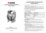
PARTS LIST / PD30X-X-B AIR SECTION
.
T
ORQUE REQUIREMENTS
,
NOTE: DO NOT OVERTIGHTEN FASTENERS
ALL FASTENERS ARE METRIC
Torque (134) Screw to 40 Ć 50 in. lbs (4.5 Ć 5.6 Nm).
MAJOR VALVE CROSS SECTION DETAIL
109 110k
112
114k
113k
115 111
116
FIGURE 3
LUBRICA
TION / SEALANTS
k Apply Lubriplate FMLĆ2 Grease to O" rings, U" Cups
& mating parts.
147 k
146 k
MAJOR
V
ALVE
PILOT VALVE
PART GROUP
118
111
169 k
121
109
133
See cross section
detail figure 3 above.
IMPORTANT
BE CERTAIN TO ORIENT (115) SPACER LEGS
AWAY FROM BLOCKING INTERNAL PORTS
WHEN REASSEMBLING AIR SECTION.
174 k
121
173 k
118
168 k
171 k
170
172 k
173 k
166 u k
167
136
110 k
177
114 k
132 k
176
174 k
103
181 (PD30SĆ only)
135
.134
107
112
113 k
114 k
115
116
u Substitute these
O" rings for 166"
on models PD30S.
FIGURE 2
101
114 k
114 k
113 k
Optional 94117 Muffler
A Major Valve Service Asm. is available separately, which includes the following:
Valve Assembly Pump Models Items Included
67089Ć1 PD30AĆ 107 Ć 116, 132, 135, 136, 166, 176, 177
67089Ć2 PD30SĆ 107 Ć 116, 132, 135, 136, 146, 147, 176, 177

PD30XĆXĆBPAGE 8 OF 8
TROUBLE SHOOTING
Product discharged from exhaust outlet.
S Check for diaphragm rupture.
S Check tightness of (14) cap screw.
Air bubbles in product discharge.
S Check connections of suction plumbing.
S Check O" rings between intake manifold and fluid caps.
S Check tightness of (14) cap screw.
Motor blows air or stalls.
S Check (176) check valve for damage or wear.
S Check for restrictions in valve / exhaust.
Low output volume, erratic flow, or no flow.
S Check air supply.
S Check for plugged outlet hose.
S Check for kinked (restrictive) outlet material hose.
S Check for kinked (restrictive) or collapsed inlet material hose.
S Check for pump cavitation Ć suction pipe should be sized at least as
large as the inlet thread diameter of the pump for proper flow if high
viscosity fluids are being pumped. Suction hose must be a nonĆcolĆ
lapsing type, capable of pulling a high vacuum.
S Check all joints on the inlet manifolds and suction connections.
These must be air tight.
S Inspect the pump for solid objects logged in the diaphragm chamĆ
ber or the seat area.
DIMENSIONAL
DA
TA
(Dimensions shown are for reference only, they are displayed in inches and millimeters (mm).
(PD30XĆAXXĆXXXĆB) 3 Ć 8 N.P.T.F. Ć 1
(PD30XĆBXXĆXXXĆB) Rp 3 (3 Ć 11 BSP parallel)
PN 97999Ć813
Air Inlet
3/4 Ć 14 N.P.T.F. Ć 1
OUTLET
FIGURE 4
Dotted lines show optional
67263 Muffler Assembly.
D009
OPTIONAL ACCESSORY: 66109 Airline Connection Kit
2Ć3/4"
(69.9 mm)
15" (381 mm)
17Ć11/16" (449.2 mm)
23Ć3/32" (586.3 mm)
10Ć5/32" (258 mm)
A"
9/16" Slot
(14.3 mm)
12Ć1/16" (306.5 mm)
30"
(761.7 mm)
B"
C"
32"
(812.5 mm)
Exhaust Port
1Ć1/2 Ć 11Ć1/2 N.P.T.
INLET
A" B" C"
PD30XĆXAX 23Ć5/8" (598.7 mm) 2Ć3/8" (60.3 mm) 11" (279.4 mm)
PD30XĆXCX 23Ć5/8" (598.7 mm) 2Ć7/16" (61.1 mm) 11Ć11/16" (296.1 mm)
PD30XĆXHX 23Ć1/8" (587.3 mm) 2Ć3/4" (69.9 mm) 11Ć11/16" (296.1 mm)
PD30XĆXSX 23Ć1/8" (587.3 mm) 2Ć3/4" (69.9 mm) 11Ć11/16" (296.1 mm)
/