Page is loading ...

Universal Metering System DSUa Mini
Metering frame complete with all pipework
Assembly and operating instructions
A2700
EN
Original operating instructions (2006/42/EC)982011 Version: BA DST 012 02/19 EN
Please carefully read these operating instructions before use. · Do not discard.
The operator shall be liable for any damage caused by installation or operating errors.
The latest version of the operating instructions are available on our homepage.

In order to make it easier to read, this document uses the male
form in grammatical structures but with an implied neutral sense. It
is aimed equally at both men and women. We kindly ask female
readers for their understanding in this simplification of the text.
Please read the supplementary information in its entirety.
Information
This provides important information relating to the
correct operation of the unit or is intended to make
your work easier.
Warning information
Warning information includes detailed descriptions of the haz‐
ardous situation, see
Ä Chapter 2.2 ‘Labelling of Warning Informa‐
tion’ on page 14
.
The following symbols are used to highlight instructions, links, lists,
results and other elements in this document:
Tab. 1: More symbols
Symbol Description
Action, step by step.
⇨ Outcome of an action.
Links to elements or sections of these instructions or other applicable documents.
n
List without set order.
[Button]
Display element (e.g. indicators).
Operating element (e.g. button, switch).
‘Display /GUI’
Screen elements (e.g. buttons, assignment of function keys).
CODE
Presentation of software elements and/or texts.
General non-discriminatory approach
Supplementary information
Supplemental directives
2

Table of contents
1 About this product................................................................. 4
1.1 Technical details........................................................... 4
1.2 Identity code................................................................. 5
1.3 Metering system, 1 pump, 1 point of injection.............. 9
1.4 Metering system, 2 pumps, 1 point of injection........... 10
1.5 Metering system, 2 pumps, 2 points of injection......... 11
2 Safety and responsibility..................................................... 13
2.1 User qualification........................................................ 13
2.2 Labelling of Warning Information................................ 14
2.3 General safety notes................................................... 15
2.4 Intended Use.............................................................. 18
3 Storage and Transport........................................................ 19
4 Assembly and installation................................................... 20
4.1 General....................................................................... 20
4.2 Installation on the floor................................................ 21
4.3 Installation with stainless steel bracket....................... 22
4.4 Installation on the wall................................................ 22
4.5 Connect the suction lance level gauge....................... 23
5 Commissioning................................................................... 24
5.1 Leaks and Emissions.................................................. 24
5.2 Personal Protective Equipment (PPE)........................ 25
5.3 Commissioning Test Run............................................ 25
5.4 Connecting the Chemical Tank for Commissioning.... 26
6 Operation of the Metering System...................................... 27
7 Maintenance and Troubleshooting...................................... 28
7.1 Maintenance............................................................... 29
7.2 Troubleshooting.......................................................... 31
8 Decommissioning and disposal.......................................... 33
8.1 Disposal of used parts................................................ 34
9 Technical data..................................................................... 35
10 Drawings............................................................................. 37
10.1 Metering system, 1 pump, 1 point of injection.......... 37
10.2 Metering system, 2 pumps, 1 point of injection......... 38
10.3 Metering system, 2 pumps, 2 points of injection....... 39
11 Flow diagram of DSUa mini (PID)....................................... 40
11.1 Legend for flow diagrams......................................... 40
11.2 Flow diagram of DSUa mini 1 (PID).......................... 41
11.3 Flow diagram of DSUa mini 2 (PID).......................... 42
11.4 Flow diagram of DSUa mini 3 (PID).......................... 43
12 Electrical wiring diagram..................................................... 44
12.1 Electrical Wiring Diagram, 1062129, 1 Pump........... 44
12.2 Electrical wiring diagram, 2 pumps........................... 46
13 Declaration of Conformity for Machinery............................. 48
14 Index................................................................................... 49
Table of contents
3

1 About this product
1.1 Technical details
The metering system DULCODOS
®
universal combines standard
components with the solenoid-driven metering pump you have
selected. For the reliable metering of liquid chemicals.
Technical details:
n Solenoid-driven metering pumps Beta
®
4/5
n delta
®
n gamma/ X
n Dimensions: 850x580x410 mm or 1000x680x410 mm (H x W x
D)
n Material combinations: PP/FKM or PVC/EPDM. Pay attention
to compatibility with the feed chemical.
n Relief valves to protect the pipework
n Manometer
n Collecting pan with leak sensor
n Flushing connectors
n Terminal box with master switch
n The assembly frame is available in 6 standard colours
WARNING!
Danger from hazardous substances!
Possible consequence: Fatal or very serious inju‐
ries.
Please ensure when handling hazardous sub‐
stances that you have read the latest safety data
sheets provided by the manufacture of the haz‐
ardous substance. The actions required are
described in the safety data sheet. Check the
safety data sheet regularly and replace, if neces‐
sary, as the hazard potential of a substance can be
re-evaluated at any time based on new findings.
The system operator is responsible for ensuring
that these safety data sheets are available and that
they are kept up to date, as well as for producing
an associated hazard assessment for the worksta‐
tions affected.
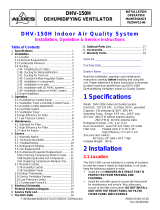
A2355
Fig. 1: Nameplate
Metering of liquid chemicals, e.g.
n Cooling water treatment
n Waste water and process water treatment
n Paper industry
Nameplate
Field of application
About this product
4

1.2 Identity code
DSUa DULCODOS universal mini
Pipework / Seal / Function
A PVC, EPDM, for 1 pump and 1 point of injection
B PVC, EPDM, for 2 pumps and 1 point of injection
C PVC, EPDM, for 2 pumps and 2 points of injection
D PP, FKM, for 1 pump and 1 point of injection
E PP, FKM, for 2 pumps and 1 point of injection
F PP, FKM, for 2 pumps and 2 points of injection
Assembly frame
A PP, white, 850x580x410 mm (HxWxD) for (A/D)
B PP, white, 1000x680x410 mm (HxWxD) for (B/E)
C PP, white, 850x880x410 mm (HxWxD) for (C/F)
Design
00 with ProMinent logo
01 without ProMinent logo
Pulsation damper
0 none
1 1 x pulsation damper PVC/ EPDM
2 1 x pulsation damper PP/FKM
3 2 x pulsation damper PVC/ EPDM
4 2 x pulsation dampers PP/FKM
Hydraulic connectors
0 Insert
1 Hose nipple 6x4
2 Hose nipple 8x5
3 Hose nipple 12x9
4 Pressure hose nozzle DN10
5 Pressure hose nozzle 1/2" NPT
Flushing connectors
0 closed
1 Pressure hose nozzle DN10
2
Gardena
®
3 Pressure hose nozzle 1/2" NPT
Splash guard
0 none
A Splash guard for (A/D)
B Splash guard for (B/E)
About this product
5

DSUa DULCODOS universal mini
C Splash guard for (C/F)
Stainless steel bracket
D No stainless steel bracket
A Stainless steel bracket (H= 150 mm) + machine feet for (A/D)
B Stainless steel bracket (H= 150 mm) + machine feet for (B/E)
C Stainless steel bracket (H= 150 mm) + machine feet for (C/F)
Pump 1
00 no pump
Beta
®
4
41 10 bar / 0.74 l/h, BT4b 1000 PVT, 6x4
42 16 bar / 2.2 l/h, BT4b 1602 PVT, 6x4
43 16 bar / 3.60 l/h, BT4b 1604 PVT, 6x4
44 7 bar / 7.10 l/h, BT4b 0708 PVT, 8x5
45 4 bar / 12.30 l/h, BT4b 0413 PVT, 8x5
46 2 bar / 19.00 l/h, BT4b 0220 PVT, 12x9
Beta
®
5
51 10 bar / 6.80 l/h, BT5b 1008 PVT, 8x5
52 7 bar / 11.0 l/h, BT5b 0713 PVT, 8x5
53 4 bar / 17.10 l/h, BT5b 0420 PVT, 12x9
54 2 bar / 32.00 l/h, BT5b 0232 NPE, 12x9
delta
®
:
D1 16 bar / 11.3 l/h, DLTa 1612 PVT, 8x5
D2 10 bar / 19.1 l/h, DLTa 1020 PVT, 12x9
D3 7 bar / 29.2 l/h, DLTa 0730 PVT, 12x9
D4 4 bar / 49.0 l/h, DLTa 0450 PVT, DN10
D5 2 bar / 75.0 l/h, DLTa 0280 PVT, DN10
gamma/ X
®
:
X1 16 bar / 3.6 l/h, GMXa 1604 PVT, 6x4
X2 7 bar / 7.6 l/h, GMXa 0708 PVT, 8x5
X3 10 bar / 9.0 l/h, GMXa 1009 PVT, 8x5
X4 4 bar / 13.5 l/h, GMXa 0414 PVT 8x5
X5 7 bar / 14.5 l/h, GMXa 0715 PVT, 8x5
X6 2 bar / 19.7 l/h, GMXa 0220 PVT, 12x9
X7 4 bar / 24.0 l/h, GMXa 0424 PVT, 12x9
X8 2 bar / 45.0 l/h, GMXa 0245 PVT, 12x9
Pump 2
00 no pump
About this product
6

DSUa DULCODOS universal mini
Beta
®
4
41 10 bar / 0.74 l/h, BT4b 1000 PVT, 6x4
42 16 bar / 2.2 l/h, BT4b 1602 PVT, 6x4
43 16 bar / 3.60 l/h, BT4b 1604 PVT, 6x4
44 7 bar / 7.10 l/h, BT4b 0708 PVT, 8x5
45 4 bar / 12.30 l/h, BT4b 0413 PVT, 8x5
46 2 bar / 19.00 l/h, BT4b 0220 PVT, 12x9
Beta
®
5
51 10 bar / 6.80 l/h, BT5b 1008 PVT, 8x5
52 7 bar / 11.0 l/h, BT5b 0713 PVT, 8x5
53 4 bar / 17.10 l/h, BT5b 0420 PVT, 12x9
54 2 bar / 32.00 l/h, BT5b 0232 NPE, 12x9
delta
®
:
D1 16 bar / 11.3 l/h, DLTa 1612 PVT, 8x5
D2 10 bar / 19.1 l/h, DLTa 1020 PVT, 12x9
D3 7 bar / 29.2 l/h, DLTa 0730 PVT, 12x9
D4 4 bar / 49.0 l/h, DLTa 0450 PVT, N10
D5 2 bar / 75.0 l/h, DLTa 0280 PVT, DN10
gamma/ X
®
:
X1 16 bar / 3.6 l/h, GMXa 1604 PVT, 6x4
X2 7 bar / 7.6 l/h, GMXa 0708 PVT, 8x5
X3 10 bar / 9.0 l/h, GMXa 1009 PVT, 8x5
X4 4 bar / 13.5 l/h, GMXa 0414 PVT, 8x5
X5 7 bar / 14.5 l/h, GMXa 0715 PVT, 8x5
X6 2 bar / 19.7 l/h, GMXa 0220 PVT, 12x9
X7 4 bar / 24.0 l/h, GMXa 0424 PVT, 12x9
X8 2 bar / 45.0 l/h, GMXa 0245 PVT, 12x9
Operating instructions
CS Czech
EN German
EN English
ES Spanish
FR French
IT Italian
PT Portuguese
All other languages are available on request.
About this product
7

DSUa DULCODOS universal mini
Certification
01 CE certification
About this product
8

1.3 Metering system, 1 pump, 1 point of injection
600
1
2
13
4
5
6
7
8
13
10
A
C
B
11
410
10
58010
320
300
12
9
63 40
127
52
850
110
150
A2699
Fig. 2: Metering system, 1 pump, 1 point of injection, all dimensions in mm
A Feed
B Outlet
C Drain
Not shown Connecting parts for flushing pipe DN10,
2 no.
# Name Material/type Dimension Material Quan‐
tity
Part number
1 Assembly frame - 600x850x400 PP 1 -
2 Metering pump To be selected by the
customer.
- - 1 -
3 Pulsation damper
Hidracar
®
U001
0.09 litres PVC-U 1 1057944
4 Manometer MDM902 d25 / G1/4" PVC-U 1 1030362
5 DHV DHV-U DN10 PVC-U 1 1037765
6 Back pressure
valve
DHV-U DN10 PVC-U 1 1037765
7 Vacuum pump
Hubinont
®
MI8121 - 1 1031565
8 Vacuum cylinder - DN10 PVC-U 1 1025699
9 Ball valve 546 DN10 PVC-U 2 1024538
10 Level switch PP1/PE - - 1 142086
11 Splash guard PVC glass - - 1 -
About this product
9

# Name Material/type Dimension Material Quan‐
tity
Part number
12 Terminal box - 180x110x90 mm - 1 1036995
13 3-way ball valve 543 DN10 PVC-U 2 1043568
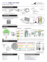
1.4 Metering system, 2 pumps, 1 point of injection
700
10 680
10
1000
63 40
110
150
52
126
410
300
90210
360
410 180
1
2
3
4
5
6
7
8
9
10
11
12 13
14
A
C
B
46
A2701
Fig. 3: Metering system, 2 pumps, 1 point of injection
A Feed
B Outlet
C Drain
Not shown Connecting parts for flushing pipe DN10,
2 no.
# Name Material/type Dimension Material Quan‐
tity
Part number
1 Assembly frame - 700x1000x400 PP 1 -
2 Metering pump To be selected by the
customer.
- - 2 -
3 Pulsation damper
Hidracar
®
U001
0.09 litres PVC-U 1 1057944
4 Manometer MDM902 d25 / G1/4" PVC-U 1 1030362
About this product
10

# Name Material/type Dimension Material Quan‐
tity
Part number
5 DHV DHV-U DN10 PVC-U 1 1037765
6 Back pressure
valve
DHV-U DN10 PVC-U 1 1037765
7 Vacuum pump
Hubinont
®
MI8121 - 1 1031565
8 Vacuum cylinder - DN10 PVC-U 1 1025699
9 Ball valve 546 DN10 PVC-U 3 1024538
10 Level switch PP1/PE - - 1 142086
11 Splash guard PVC glass - - 1 -
12 Terminal box - 180x110x90 mm - 1 1036995
13 3-way ball valve 543 DN10 PVC-U 2 1043568
14 Non-return valve 360 ND10 PVC-U 2 -
1.5 Metering system, 2 pumps, 2 points of injection
900
880
10
10
850
63
40
52
127
46
110
150
412
300
460 290
A
C
B
B
1
2
3
4
5
6
7
8
9
10
11
12
13
A2702
Fig. 4: Metering system, 2 pumps, 2 points of injection
A Feed
B Outlet
C Drain
Not shown Connecting parts for flushing pipe DN10,
2 no.
About this product
11

# Name Material/type Dimension Material Quan‐
tity
Part number
1 Assembly frame - 700x1000x400 PP 1 -
2 Metering pump To be selected by the
customer.
- - 2 -
3 Pulsation damper
Hidracar
®
U001
0.09 litres PVC-U 2 1057944
4 Manometer MDM902 d25 / G1/4" PVC-U 2 1030362
5 DHV DHV-U DN10 PVC-U 2 1037765
6 Back pressure
valve
DHV-U DN10 PVC-U 2 1037765
7 Vacuum pump
Hubinont
®
MI8121 - 1 1031565
8 Vacuum cylinder - DN10 PVC-U 1 1025699
9 Ball valve 546 DN10 PVC-U 3 1024538
10 Level switch PP1/PE - - 1 142086
11 Splash guard PVC glass - - 1 -
12 Terminal box - 180x110x90 mm - 1 1036995
13 3-way ball valve 543 DN10 PVC-U 3 1043568
About this product
12

2 Safety and responsibility
2.1 User qualification
WARNING!
Danger of injury with inadequately qualified per‐
sonnel
The operator of the system / equipment is respon‐
sible for ensuring that the qualifications are ful‐
filled.
If inadequately qualified personnel work on the unit
or loiter in the hazard zone of the unit, this could
result in dangers that could cause serious injuries
and material damage.
– All work on the unit should therefore only be
conducted by qualified personnel.
– Unqualified personnel should be kept away
from the hazard zone.
The pertinent accident prevention regulations, as
well as all other generally acknowledged safety
regulations, must be adhered to.
Training Definition
Instructed personnel An instructed person is deemed to be a person who has been instructed and,
if required, trained in the tasks assigned to him and possible dangers that
could result from improper behaviour, as well as having been instructed in the
required protective equipment and protective measures.
Trained user A trained user is a person who fulfils the requirements made of an instructed
person and who has also received additional training specific to the system
from the manufacturer or another authorised distribution partner.
Trained, qualified per‐
sonnel
A trained, qualified employee is deemed to be a person who is able to assess
the tasks assigned to him and recognize possible hazards based on his
training, knowledge and experience, as well as knowledge of pertinent regula‐
tions. A trained, qualified employee must be able to perform the tasks
assigned to him independently with the assistance of drawing documentation
and parts lists. The assessment of a person's technical training can also be
based on several years of work in the relevant field.
Electrical technician An electrical technician is able to complete work on electrical systems and rec‐
ognise and avoid possible dangers independently based on his technical
training and experience as well as knowledge of pertinent standards and regu‐
lations. An electrical technician must be able to perform the tasks assigned to
him independently with the assistance of drawing documentation, parts lists,
terminal and circuit diagrams. The electrical technician must be specifically
trained for the working environment in which the electrical technician is
employed and be conversant with the relevant standards and regulations.
Service The Service department refers to service technicians, who have received
proven training and have been authorised by the manufacturer to work on the
system.
Safety and responsibility
13

2.2 Labelling of Warning Information
These operating instructions provide information on the technical
data and functions of the product. These operating instructions pro‐
vide detailed warning information and are provided as clear step-
by-step instructions.
The warning information and notes are categorised according to
the following scheme. A number of different symbols are used to
denote different situations. The symbols shown here serve only as
examples.
DANGER!
Nature and source of the danger
Consequence: Fatal or very serious injuries.
Measure to be taken to avoid this danger.
Description of hazard
– Denotes an immediate threatening danger. If
the situation is disregarded, it will result in fatal
or very serious injuries.
WARNING!
Nature and source of the danger
Possible consequence: Fatal or very serious inju‐
ries.
Measure to be taken to avoid this danger.
– Denotes a possibly hazardous situation. If the
situation is disregarded, it could result in fatal
or very serious injuries.
CAUTION!
Nature and source of the danger
Possible consequence: Slight or minor injuries.
Material damage.
Measure to be taken to avoid this danger.
– Denotes a possibly hazardous situation. If the
situation is disregarded, it could result in slight
or minor injuries. May also be used as a
warning about material damage.
NOTICE!
Nature and source of the danger
Damage to the product or its surroundings.
Measure to be taken to avoid this danger.
– Denotes a possibly damaging situation. If the
situation is disregarded, the product or an
object in its vicinity could be damaged.
Introduction
Safety and responsibility
14

Type of information
Hints on use and additional information.
Source of the information. Additional measures.
–
Denotes hints on use and other useful informa‐
tion. It does not indicate a hazardous or dam‐
aging situation.
2.3 General safety notes
WARNING!
Danger from hazardous substances!
Possible consequence: Fatal or very serious inju‐
ries.
Please ensure when handling hazardous sub‐
stances that you have read the latest safety data
sheets provided by the manufacture of the haz‐
ardous substance. The actions required are
described in the safety data sheet. Check the
safety data sheet regularly and replace, if neces‐
sary, as the hazard potential of a substance can be
re-evaluated at any time based on new findings.
The system operator is responsible for ensuring
that these safety data sheets are available and that
they are kept up to date, as well as for producing
an associated hazard assessment for the worksta‐
tions affected.
WARNING!
Live parts
Possible consequence: Fatal or very serious inju‐
ries
– Measure: Disconnect the mains plug prior to
opening the housing
– De-energise damaged, defective or manipu‐
lated units by disconnecting the mains plug
Immediately disconnect the pump from the
mains/power supply if the pump housing has
been damaged. Only start up the pump again
after it has been repaired by authorised per‐
sonnel.
Safety and responsibility
15

WARNING!
Operating error / Unauthorised access
Possible consequence: Fatal or very serious inju‐
ries.
– Measure: Ensure that there can be no unau‐
thorised access to the device
– Ensure that the device is only operated by ade‐
quately qualified and technically expert per‐
sonnel
– Please also observe the operating instructions
for controllers and fittings and any other units,
such as sensors, sample water pumps ...
– The operator is responsible for ensuring that
personnel are qualified
WARNING!
Use of the unit in areas at risk from explosion
Possible consequence: Fatal or very serious inju‐
ries.
Operating the unit in areas at risk from explosion.
The unit is not approved to pump media at risk
from explosion.
WARNING!
Pumping flammable media
Possible consequence: Fatal or very serious inju‐
ries.
Take appropriate safety precautions when
pumping flammable media. Observe the safety
data sheet for the medium.
CAUTION!
Securing the unit
Only operate the unit when fixed to a wall or sim‐
ilar.
CAUTION!
Caution: feed chemical spraying around
The metering pump can generate a multiple of its
rated pressure. Hydraulic parts can burst if a dis‐
charge line is blocked.
Fit a relief valve in the discharge line.
Safety and responsibility
16

CAUTION!
Caution: backflow
Metering pumps are not absolutely leak-tight shut-
off devices.
Use a shut-off valve, a solenoid valve or a vacuum
breaker as an absolutely leak-tight shut-off device.
CAUTION!
Personnel injury and material damage / Unit starts
immediately
The pump can start to pump as soon as it is con‐
nected to mains voltage.
Only connect the device to the mains voltage when
all installation work has been completed and the
pumped chemicals can no longer escape in an
uncontrolled manner.
Install an emergency cut-off switch in the pump
power supply line or integrate the pump in the
emergency cut-off management of the system.
CAUTION!
Contact with chemicals
De-pressurise, drain and rinse the hydraulic part of
the unit before working on it.
Flushing connections
Both flushing connections can always remain
closed in normal mode.
In the event of an electrical accident, disconnect the mains cable
from the mains/power supply or press the emergency cut-off switch
fitted on the side of the system. If feed chemical is escaping, switch
off the pump by pressing
[Stop/Start]
. If necessary ensure that the
hydraulic system around the pump is at atmospheric pressure.
Adhere to the safety data sheet for the feed chemical.
Information in the event of an emer‐
gency
Safety and responsibility
17

2.4 Intended Use
Intended Use
Only use the metering system to meter liquid feed
chemicals into hydraulic systems.
The metering system is not intended for the
metering of gaseous or solid media.
Only use the metering system in accordance with
the technical data and specifications provided in
these operating instructions and in the operating
instructions for the individual components (such as
sensors, fittings, calibration devices, metering
pumps etc.).
The metering system is designed for installation
indoors. Operation outdoors is not permitted.
Do not operate the metering system under condi‐
tions other than those described in the technical
data.
Only allow technically expert personnel to operate
the metering system.
All other uses or modifications are prohibited.
Safety and responsibility
18

3 Storage and Transport
n User qualification: instructed user, see
Ä Chapter 2.1 ‘User
qualification’ on page 13
WARNING!
Danger from hazardous substances!
Possible consequence: Fatal or very serious inju‐
ries.
Please ensure when handling hazardous sub‐
stances that you have read the latest safety data
sheets provided by the manufacture of the haz‐
ardous substance. The actions required are
described in the safety data sheet. Check the
safety data sheet regularly and replace, if neces‐
sary, as the hazard potential of a substance can be
re-evaluated at any time based on new findings.
The system operator is responsible for ensuring
that these safety data sheets are available and that
they are kept up to date, as well as for producing
an associated hazard assessment for the worksta‐
tions affected.
Hazardous feed chemicals (hazardous sub‐
stances)
Prior to storage or transportation, make sure that
the metering system is free from hazardous feed
chemicals.
Immediately check the goods on receipt of delivery. Identify any
damage caused by transportation as well as missing parts or incor‐
rect delivery. Immediately notify us of defects in writing upon
receipt of the goods.
Only transport the metering system standing and secured with ten‐
sioning straps.
Only transport the metering system on a pallet.
The metering system cannot be stacked.
Suitable hoisting and lifting equipment must be used for loading
and unloading packed machine components. Make sure that the
lifting equipment and means of transportation have sufficient load-
bearing capacity.
When using forklifts, the forks must be sufficiently long to reach
beyond the overall depth of the packaging and the spacing
between the forks must also be sufficient.
Store and transport the metering system in an environment free
from dust.
Do not expose the metering system to direct sunlight of UV radia‐
tion.
Storage and transport temperature of the metering system: -5 °C ...
+50 °C
Maximum air humidity *: 92 % relative air humidity
Storage and Transport
19

4 Assembly and installation
4.1 General
n User qualification, mechanical installation: trained and qualified
personnel
Ä Chapter 2.1 ‘User qualification’ on page 13
n User qualification, electrical installation: electrical technician
Ä Chapter 2.1 ‘User qualification’ on page 13
Intended use
The metering system is designed for installation
indoors. Operation outdoors is not permitted.
Do not operate the metering system under condi‐
tions other than those described in the technical
data.
Only allow adequately qualified and technically
expert personnel to operate the metering system.
All other uses or modifications are prohibited.
1. Only fix the metering system on the feet intended for this pur‐
pose or as a wall panel on the wall.
2. Ensure that the fixing surface is level (e.g. DIN 18202).
3. Tighten all connectors (threaded connectors, flange connec‐
tors ...).
1. When installing the metering system, always make sure that
the connectors on site are connected to the metering system
free of tension.
2. Only use materials that comply with the provisions and speci‐
fications of the ProMinent resistance list.
Installation work:
Hydraulic installation:
Assembly and installation
20
/