Page is loading ...

E2003 CCN 99712788
& (419) 636-4242 D FAX (419) 633-1674
INGERSOLL-RAND COMPANY
P.O. BOX 151 D ONE ARO CENTER D BRYAN, OHIO 43506Ć0151
OPERATOR’S MANUAL
PD02P-X
RELEASED: 10-1-96
REVISED: 11-12-03
(REV. L)
INCLUDING: OPERATION, INSTALLATION & MAINTENANCE
1/4” DIAPHRAGM PUMP
1:1 RATIO (NON-METALLIC)
READ THIS MANUAL CAREFULLY BEFORE INSTALLING,
OPERATING OR SERVICING THIS EQUIPMENT.
It is the responsibility of the employer to place this information in the hands of the operator. Keep for future reference.
SERVICE KITS
Refer to Service Kit Chart to match pump material with Service Kits ofĆ
fered. The X" represents a variable digit of the Model Number.
637276 Air Valve Kit.
637313ĆXX for Pump Wet End Repair (model digits 7 and 11).
637314ĆXX for Pump Rebuild (model digits 7 and 11).
PUMP DATA
Models see Model Description Chart" for ĆXXX".. . . . . . . .
Pump Type NonĆMetallic Air Operated Double Diaphragm.. . . . .
Material see ``Model Description Chart".. . . . . . . .
Weight Polypropylene 4.08 lbs (1.85 kgs). . . . . . . . . . . . .
Groundable Acetal 4.64 lbs (2.10 kgs). . . . . .
PVDF (KynarR) 4.9 lbs (2.22 kgs). . . . . . . .
Maximum Air Inlet Pressure 100 p.s.i.g. (6.9 bar). . . . . . . . .
Minimum Air Inlet Pressure 20 p.s.i.g. (1.4 bar). . . . . . . . .
Maximum Outlet Pressure 100 p.s.i.g. (6.9 bar). . . . . . . . . .
Maximum Flow Rate 4.6 g.p.m. (17.4 liters). . . . . . . . . . . . . .
Maximum Suction Lift 20 ft. (water). . . . . . . . . . . . .
Maximum Output Per Cycle 0.014 gallons (53 cc's). . . . . . . . .
Maximum Particle Size clean fluid only. . . . . . . . . . . .
Maximum Temperature Limits
E.P.R. / EPDM Ć60_ to 280_ F (Ć51_ to 138_ C). . . . . . . . . . .
Groundable Acetal 10_ to 180_ F (Ć12_ to 82_ C). . . . . . . .
Nitrile 10_ to 180_ F (Ć12_ to 82_ C). . . . . . . . . . . . . . . . .
Polypropylene 35_ to 150_ F (2_ to 66_ C). . . . . . . . . . .
PVDF (Kynar) 10_ to 200_ F (Ć12_ to 93_ C). . . . . . . . . . .
SantopreneR Ć40_ to 225_ F (Ć40_ to 107_ C). . . . . . . . . . .
T.F.E. (TeflonR)40_ to 225_ F (4_ to 107_ C). . . . . . . . . .
Groundable PD02PĆXDSĆDTX models only.. . . . . . . . . . . . . . . .
Dimensional Data see page 8.. . . . . . . . . . . . . . . .
Noise Level @ 70 p.s.i., 60 c.p.m. 59.8 db(A)¬. . . . .
¬ The pump sound pressure levels published here have been updated to an Equivalent Continuous Sound
Level (L
Aeq
) to meet the intent of ANSI S1.13Ć1971, CAGIĆPNEUROP S5.1 using four microphone locaĆ
tions.
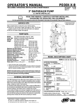
NOTICE: All possible options are shown in the chart. However, certain
combinations may not be recommended, consult a representative or the
factory if you have questions concerning availability.
PD02PĆXXSĆXTX
1/4" DIAPHRAGM PUMP
MODEL DESCRIPTION CHART
PD02 P Ć X X S Ć X T X
PD02P Ć X X S Ć X T X
637313 Ć X X
Diaphragm Material
Wet End Material
FLUID SECTION SERVICE KIT SELECTION
EXAMPLE: MODEL # PD02PĆADSĆDTA
FLUID SECTION SERVICE KIT # 637313ĆDA
WET END / FLUID CAP / MANIFOLD MATERIAL
D - Groundable Acetal
K - PVDF (Kynar)
P - Polypropylene
CHECK VALVE SEAT MATERIAL
D - Groundable Acetal
K - PVDF (Kynar)
P - Polypropylene
DIAPHRAGM / O" RING MATERIAL
A - Santoprene / E.P.R.
G - Nitrile / Nitrile
T - T.F.E. (Teflon) / T.F.E. (Teflon) / Nitrile
CENTER BODY MATERIAL
P - Polypropylene
INLET / OUTLET
A - Single Inlet / Single Outlet
D - Single Inlet / Double Outlet
E - Double Inlet / Single Outlet
H - Double Inlet / Double Outlet
HARDWARE MATERIAL
S - Stainless Steel
CHECK MATERIAL
T - T.F.E. (Teflon)

PD02PĆXPage 2 of 8
OPERATING AND SAFETY PRECAUTIONS
READ, UNDERSTAND, AND FOLLOW THIS INFORMATION TO AVOID INJURY AND PROPERTY DAMAGE.
EXCESSIVE AIR PRESSURE
STATIC SPARK
HAZARDOUS MATERIALS
HAZARDOUS PRESSURE
WARNING
EXCESSIVE AIR PRESSURE. Can cause personĆ
al injury, pump damage or property damage.
S Do not exceed the maximum inlet air pressure as stated on the
pump model plate.
S Be sure material hoses and other components are able to withĆ
stand fluid pressures developed by this pump. Check all hoses
for damage or wear. Be certain dispensing device is clean and
in proper working condition.
WARNING
STATIC SPARK. Can cause explosion resulting in
severe injury or death. Ground pump and pumping system.
S PD02PĆXDSĆDTX Groundable Acetal pumps: Use the pump
grounding screw provided. A screw terminal is provided on the
manifold. Connect a 12 ga. (min.) wire (66885Ć1 kit is available)
to a good earth ground source.
S The pumping system and object being sprayed must be
grounded when it is pumping, flushing, recirculating or sprayĆ
ing flammable materials such as paints, solvents, lacquers,
etc. or used in a location where surrounding atmosphere is
conducive to spontaneous combustion.
S Use the pump grounding screw terminal provided. Use Aro
Part No. 66885Ć1 Ground Kit or connect a suitable ground wire
(12 ga. min.) to a good earth ground source.
S Secure pump, connections and all contact points to avoid
vibration and generation of contact or static spark.
S Consult local building codes and electrical codes for specific
grounding requirements.
S After grounding, periodically verify continuity of electrical path
to ground. Test with an ohmmeter from each component (e.g.,
hoses, pump, clamps, container, spray gun, etc.) to ground to
insure continuity. Ohmmeter should show 0.1 ohms or less.
S Submerse the outlet hose end, dispensing valve or device in
the material being dispensed if possible. (Avoid free streaming
of material being dispensed.)
S Use hoses incorporating a static wire.
S Use proper ventilation.
S Keep inflammables away from heat, open flames and sparks.
S Keep containers closed when not in use.
WARNING
Pump exhaust may contain contaminants. Can
cause severe injury. Pipe exhaust away from work area and perĆ
sonnel.
S In the event of a diaphragm rupture material can be forced out
of the air exhaust muffler.
S Pipe the exhaust to a safe remote location when pumping hazĆ
ardous or inflammable materials.
S Use a grounded 1/4" minimum i.d. hose between the pump and
the muffler.
WARNING
HAZARDOUS PRESSURE. Can result in serious
injury or property damage. Do not service or clean pump,
hoses or dispensing valve while the system is pressurized.
S Disconnect air supply line and relieve pressure from the sysĆ
tem by opening dispensing valve or device and / or carefully
and slowly loosening and removing outlet hose or piping from
pump.
WARNING
HAZARDOUS MATERIALS. Can cause serious inĆ
jury or property damage. Do not attempt to return a pump to the
factory or service center that contains hazardous material.
Safe handling practices must comply with local and national
laws and safety code requirements.
S Obtain Material Safety Data Sheets on all materials from the
supplier for proper handling instructions.
CAUTION
Verify the chemical compatibility of the pump
wetted parts and the substance being pumped, flushed or reĆ
circulated. Chemical compatibility may change with temperaĆ
ture and concentration of the chemical(s) within the
substances being pumped, flushed or circulated. For specific
fluid compatibility, consult the chemical manufacturer.
CAUTION
Maximum temperatures are based on mechaniĆ
cal stress only. Certain chemicals will significantly reduce
maximum safe operating temperature. Consult the chemical
manufacturer for chemical compatibility and temperature limĆ
its. Refer to PUMP DATA on page 1 of this manual.
CAUTION
Be certain all operators of this equipment have
been trained for safe working practices, understand it's limitaĆ
tions, and wear safety goggles / equipment when required.
CAUTION
Do not use the pump for the structural support of
the piping system. Be certain the system components are
properly supported to prevent stress on the pump parts.
S Suction and discharge connections should be flexible connecĆ
tions (such as hose), not rigid piped, and should be compatible
with the substance being pumped.
CAUTION
Prevent unnecessary damage to the pump. Do
not allow pump to operate when out of material for long periods
of time.
S Disconnect air line from pump when system sits idle for long
periods of time.
CAUTION
Use only genuine ARO replacement parts to asĆ
sure compatible pressure rating and longest service life.
NOTICE
Replacement warning labels are available upon
request: Static Spark & Diaphragm Rupture" PN \ 94080.
WARNING
CAUTION
NOTICE
= Hazards or unsafe practices which could
result in severe personal injury, death or
substantial property damage.
= Hazards or unsafe practices which could
result in minor personal injury, product or
property damage.
= Important installation, operation or
maintenance information.

Page 3 of 8PD02PĆX
GENERAL DESCRIPTION
The ARO diaphragm pump offers high volume delivery even at low air
pressures, easy self priming and the ability to pump various viscosity
materials. The pump is designed to correspond to the needs of the user
by offering a variety of wetted parts configurations to handle almost any
application.
Air operated double diaphragm pumps utilize a pressure differential in
the air chambers to alternately create suction and positive fluid pressure
in the fluid chambers. Flat checks insure a positive flow of fluid.
Pump cycling will begin as air pressure is applied and it will continue to
pump and keep up with the demand. It will build and maintain line presĆ
sure and will stop cycling once maximum line pressure is reached (disĆ
pensing device closed) and will resume pumping as needed.
Model PD02PĆXDSĆDTX: The Acetal material used in this pump conĆ
tains Stainless Steel fibers. It's conductivity allows it to be connected to a
suitable ground. A ground screw is provided for this.
AIR AND LUBE REQUIREMENTS
WARNING
EXCESSIVE AIR PRESSURE. Can cause pump
damage, personal injury or property damage.
S A filter capable of filtering out particles larger than 50 microns should
be used on the air supply. In most applications there is no lubrication
required other than the O" ring lubricant which is applied during asĆ
sembly or repair.
S The pump can be rotated 360_ to suit the application. It may be
mounted upside down or on the wall with no effect on suction lift or
operating efficiency. The filter and regulator need to be oriented in a
normal vertical direction to function properly.
S Pipe plugs are included for the material inlets. They can be switched
to accommodate piping requirements. However, the fluid inlet must
always be in the port closest to the mounting base.
S When lubricated air is necessary, supply the air lubricator with a
good grade of SAE 90 wt. nonĆdetergent oil and set the lubricator to
a rate not to exceed one drop per minute.
INSTALLATION
S
NOTICE: ReĆtorque fasteners prior to use. Refer to step #18 on
page 6 for information.
S Apply Teflon tape or pipe sealant to threads upon assembly to preĆ
vent leakage.
S Secure the diaphragm pump legs to a suitable surface to insure
against damage by vibration.
S To avoid problems, install a particle fluid filter to screen out foreign
matter 1/32" (0.79 mm) or larger in diameter.
S The pump is not recommended for submerged applications.
S When the diaphragm pump is used in a forcedĆfeed (flooded inlet)
situation, it is recommended that a Check Valve" be installed at the
air inlet.
OPERATING INSTRUCTIONS
S Always flush the pump with a solvent compatible with the material
being pumped, if the material being pumped is subject to ``setting up"
when not in use for a period of time.
S Disconnect the air supply from the pump if it is to be inactive for a few
hours.
S The outlet material volume is governed not only by the air supply, but
also by the material supply available at the inlet. The material supply
tubing should not be too small or restrictive. Be sure not to use hose
which might collapse.
MAINTENANCE
Refer to the part list on page 4 for Service Kit Information, parts view on
page 5 and Repair Procedures on page 6.
S Certain ARO Smart Parts" are indicated which should be available
for fast repair and reduction of down time.
S Service kits are divided to service two separate diaphragm pump
functions: 1. Air Section, 2. Fluid Section. The Fluid Section is dividĆ
ed further to match typical part Material Options.
S Provide a clean work surface to protect sensitive internal moving
parts from contamination from dirt and foreign matter during service
disassembly and reassembly.
S Keep good records of service activity and include pump in prevenĆ
tive maintenance program.
S TeflonR is a registered trademark of the DuPont Company, S KynarR is a trademark of Penwalt Corp.,
S SantopreneR is a registered trademark of Monsanto Company, licensed to Advanced Elastomer Systems, L.P. S LubriplateR is a registered trademark of Lubriplate Division (Fiske Brothers)

PD02PĆXPage 4 of 8
PARTS LIST / PD02P-X
637276 Air Valve Kit: Includes items 102, 111, 132, 134, 135, 137, 145, 146, 178, 179 and 94276 Lubriplate packet.
637313ĆXX Diaphragm Kit: Includes items 7, 13, 19, 22, 33, 41, 64 and 94276 Lubriplate packet.
637314ĆXX Rebuild Kit: Includes items 7, 13, 19, 22, 33, 41, 64, 102, 111, 119, 137, 144, 146, 147, 161 and 94276 Lubriplate packet.
DIAPHRAGM OPTIONS
7" 13" 19" 33" 64"
ĆXXX Diaphragm Qty [Mtl] BackĆUp Ring Qty [Mtl] Seal Qty [Mtl]
O" Ring
(.103" x .693" o.d.) Qty [Mtl]
O" Ring
(.157" x 3.424" o.d.) Qty [Mtl]
ĆXXA 93808 (2) [SP] 95127 (2) [T] 94434 (4) [E] 94437 (2) [E] ----- --- ---
ĆXXG 93808ĆG (2) [B] 95127 (2) [T] 94434ĆG (4) [B] 94438 (2) [T] ----- --- ---
ĆXXT 93898 (2) [T] 95127 (2) [T] 94435 (4) [T] 94438 (2) [T] 93947 (2) [B]
COMMON PARTS
PD02P Ć X X S Ć X T X POLYPROPYLENE ACETAL KYNAR
PD02PĆXPSĆPTX PD02PĆXDSĆDTX PD02PĆXKSĆKTX
Item Description (size in inches) Qty Part No. [Mtl] Part No. [Mtl] Part No. [Mtl]
j 1 Rod (2Ć13/16" long) (1) 93916 [C] 93916 [C] 93916 [C]
j 5 Washer (1Ć3/4" o.d.) (2) 94938 [Z] 94938 [Z] 94938 [Z]
j 6 Diaphragm Screw (1/4" Ć 20) (2) 93810Ć1 [P] 93810Ć2 [D
1
] 93810Ć3 [PK]
17 Manifold (Air Inlet) (1) 94246Ć1 [P] 94246Ć2 [G] 94246Ć4 [PK]
18 Manifold (1) 94247Ć1 [P] 94247Ć2 [G] 94247Ć4 [PK]
22 Disc (4) 94525 [T] 94525 [T] 94525 [T]
41 Spring Stop (4) 93814Ć1 [P] 93814Ć2 [D
1
] 93814Ć3 [PK]
43 Screw (#10 Ć 32 x 1") (4) 94436 [SS] 94436 [SS] 94436 [SS]
62 Nut (1/4" Ć 20) (6) 93828 [SS] 93828 [SS] 93828 [SS]
63 Pipe Plug (1/4 Ć 18 N.P.T.) (`) 93832Ć1 [P] 93832Ć2 [D
2
] 93832Ć3 [PK]
j 65 Fluid Cap (`) 94245Ć1 [P] 94245Ć2 [G] 94245Ć4 [PK]
j 66 Fluid Cap (with one blocked tube) (`) 94344Ć1 [P] 94344Ć2 [G] 94344Ć3 [PK]
j 68 Air Cap (with groove d) (1) 93804 [P] 93804 [P] 93804 [P]
j 69 Air Cap (with tongue Z) (1) 93805 [P] 93805 [P] 93805 [P]
74 Pipe Plug (3/8 Ć 18 N.P.T.) (`) 94478Ć1 [P] 94478Ć2 [D
2
] 94478Ć3 [PK]
131 Bolt (1/4" Ć 20 x 6.375") (6) 94526 [SS] 94526 [SS] 94526 [SS]
205 Logo Plate (2) 93919 [A] 93919 [A] 93919 [A]
AIR SECTION PARTS
Item Description (size in inches) Qty Part No. [Mtl] Item Description (size in inches) Qty Part No. [Mtl]
102 O" Ring (1/16" x 7/8" o.d.) (3) Y325Ć18 [B]
103 Bushing (1) 93917 [D
2
]
110 U" Cup (1/8" x 13/16" o.d.) (1) Y186Ć54 [B]
j 111 Spool Ass'y (includes items 110, 138, 180) (1) 67163 [D
2
]
119 O" Ring (.106" x .587" o.d.) (4) 15066 [B]
132 Gasket (1) 93809 [Kr]
134 Screw (#4 Ć 20 x .295") (3) 93942 [SS]
j 135 Valve Block (1) 93806 [R]
137 O" Ring (1/16" x 1" o.d.) (1) Y325Ć20 [B]
138 O" Ring (.103" x .818" o.d.) (1) 94760 [U]
144 U" Cup (1/8" x 5/8" o.d.) (2) Y186Ć45 [B]
j 145 Minor Valve Block (1) 93807 [R]
146 O" Ring (1/16" x 5/16" o.d.) (2) Y325Ć8 [B]
147 O" Ring (1/16" x 7/16" o.d.) (2) Y325Ć11 [B]
161 O" Ring (3/32" x 9/16" o.d.) (2) Y325Ć110 [B]
178 Trip Rod Assembly (includes items 119) (2) 65145 [D
2
]
179 Sleeve Assembly (includes items 119) (1) 65144 [D
2
]
180 O" Ring (.106" x .587" o.d.) (1) 15066ĆU [U]
MATERIAL CODE
[A] = Aluminum [E] = E.P.R. [P] = Polypropylene (Light Gray) [SS] = Stainless Steel
[B] = Nitrile [G] = Groundable Acetal (Dark Gray) High Density Polypropylene (Green) [T] = Teflon
[C] = Carbon Steel [Kr] = Kraton [R] = Ryton [U] = Polyurethane
[D
1
] = Acetal (Orange) [PK] = Pure Kynar [SP] = Santoprene [Z] = Zinc
[D
2]
= Acetal (White)
` Quantities will vary, depending on the inlet / outlet option selected (refer to chart on page 5).
V Smart Parts", keep these items on hand in addition to the Service Kits for fast repair and reduction of down time.

Page 5 of 8PD02PĆX
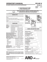
PARTS LIST / PD02P-X
111
102
102
119
146
AIR VALVE SECTION
(SHOWN 2X SCALE)
Figure 2
LUBRICATION
Apply Lubriplate grease (94276) to all
O" rings, U" cups & mating parts.
. TORQUE REQUIREMENTS ,
NOTE: DO NOT OVERTIGHTEN FASTENERS
Figure 1
62 ,
18
134 ,
178
INLET / OUTLET FLUID CAP ITEM 63 ITEM 74
(Groove)
(Tongue)
OPTIONS A" B" Qty Qty
SI / SO 65 65 (1) (1)
SI / DO 66 65 - (1)
DI / SO 65 66 (1) -
DI / DO 66 66 - -
132
145
(6) / (5) Diaphragm nut / washer 75 Ć 85 in. lbs (8.5 Ć
9.6 Nm), use Loctite #242, tighten together.
(43) Torque to 20 Ć 25 in. lbs (2.3 Ć 2.8 Nm).
(62) / (131) Manifold bolts / nuts 70 in. lbs max. (7.9
Nm max.), tighten together alternately &
evenly, then reĆtorque.
(134) Torque to 3.5 Ć 4.5 in. lbs (0.40 Ć 0.51 Nm).
102
178179
146
135137180138110
19 41 22 B"
33 13 1 6976 , 645 144 144103
68 5 6476 ,
147 A" 161
17 63 43 ,
194122
74
131 ,
205
13 33 147 161

PD02PĆXPage 6 of 8
PUMP DISASSEMBLY AND REASSEMBLY
GENERAL PUMP REPAIR NOTES:
S Tools needed to complete disassembly and repair:
S 5/16" wrench or socket, 7/16" socket, 5/8" wrench or socket, 3/8"
Allen wrench, spanner wrench, torque wrench (measuring inch
pounds), O" ring pick.
S Once the pump is disassembled, you have the opportunity to clean
and inspect all parts for wear. Look for deep scratches on metallic
surfaces and nicks or cuts in O" rings. Replace old parts with new
ones as necessary.
S Take precautions to prevent cutting O" rings upon installation.
S Lubricate ``O" rings and U" cups with Lubriplate. A packet of this luĆ
bricant is included in each Service Kit.
S Do not overĆtighten fasteners. Refer to torque specification block on
page 5.
S ReĆtorque fasteners following restart.
Service Kits available. From your local distributor.
(Kits also include Lubriplate grease packet.)
S SERVICE KIT: 637314ĆXX contains parts for a complete pump rebuild.
S SERVICE KIT: 637276 contains parts to rebuild the air valve.
S SERVICE KIT: 637313ĆXX contains parts to rebuild the diaphragms
and checks.
FLUID SECTION DISASSEMBLY
1. Place the pump on a flat workbench.
2. Using 7/16" sockets, remove six (62) nuts and (131) bolts.
3. Set the pump on end, with the air inlet" end up.
4. Using a flat blade screwdriver, remove (17) air inlet manifold and
(A") fluid cap.
5. Remove (13) backĆup ring and (33) O" ring from (A") fluid cap.
6. Remove two (147) O" rings from (A") fluid cap.
7. Remove (18) manifold and (B") fluid cap.
8. Remove (13) backĆup ring and (33) O" ring from (B") fluid cap.
9. Using 5/8" wrenches on (6) diaphragm screws, unthread and reĆ
move diaphragm assemblies.
S NOTE: Air valve section can be repaired at this time, refer to Air
Valve Disassembly".
10. Using a 5/16" wrench or flat blade screwdriver, remove two (43)
screws from (17) air inlet manifold.
11. Separate (17) air inlet manifold and (A") fluid cap. NOTE: (41)
spring stops and (22) discs may fall out. If not, remove at this time.
12. Remove (19) seals and (161) O" rings.
13. Disassembly of the opposite end of the pump is the same as the air
inlet" end, except for the following: a.) the opposite end does not
contain (161) O" rings and b.) the top tube has the outside shoulder,
the bottom tube has the inside shoulder.
14. Wrap (1) rod in a shop rag and secure in a softĆfaced vise.
15. Using a 5/8" wrench, unthread (6) diaphragm screw from (1) rod.
16. Using a 5/8" wrench on (6) diaphragm screw and a spanner wrench
on (5) washer, unthread and remove (6) diaphragm screw.
FLUID SECTION REASSEMBLY
NOTE: Lubricate all O" rings, U" cups seals and their mating parts with
94276 Lubriplate upon assembly.
1. Place the new (7) diaphragms on the (6) diaphragm screw, with the
bowed side of the diaphragm oriented against (6) diaphragm screw.
2. Assemble (5) washer to (6) diaphragm screw and torque to 75 Ć 85
in. lbs (8.5 Ć 9.6 Nm), using a spanner wrench and a 5/8" wrench.
NOTE: Be sure not to strip the plastic nut.
3. Assemble (1) rod to one of the diaphragm assemblies and tighten
finger tight.
4. Models PD02PĆXXSĆXTT only: Assemble (64) O" rings into
grooves in (68 and 69) air caps.
5. Assemble diaphragm assemblies into air caps and torque to 75 Ć 85
in. lbs (8.5 Ć 9.6 Nm), using 5/8" wrenches.
6. Assemble two (147) O" rings to the raised air passages, opposite
each other, inside (68) air cap.
7. Set (A") fluid cap on the workbench, with the tube side" down.
8. Assemble two (161) O" rings to counterbores in (A") fluid cap.
9. Assemble (22) disc and (41) spring stop to the check seat nearest the
top tube of (A") fluid cap (top tube has the shoulder on the outside).
10. Assemble (41) spring stop and (22) disc (disc on top) to check seat
nearest the bottom tube (shoulder on outside).
11. Lubricate seal grooves in (17) air inlet manifold and assemble (19)
seals to grooves.
12. Assemble (17) air inlet manifold to (A") fluid cap, aligning fluid inlet
with lower tube (shoulder on outside).
13. Secure with two (43) screws. Torque to 20 Ć 25 in. lbs (2.3 Ć 2.8 Nm),
using a 5/16" wrench.
14. Repeat steps 9 thru 13 for opposite end of pump. NOTE: The tubes
are reversed on (B") fluid cap (top tube has outside shoulder).
15. Assemble (33) O" rings and (13) backĆup rings to the outside shoulĆ
der of tubes of (A" and B") fluid caps.
16. Assemble (17) air inlet manifold and components into (68) air cap,
being sure to align groove in manifold with rib in air cap.
17. Assemble (18) manifold and components into (69) air cap, being
sure to align groove in manifold with rib in air cap.
18. Assemble six (131) bolts and (62) nuts to pump and torque to 70 in.
lbs max (7.9 Nm max), using 7/16" sockets, hold the nut, torque the
bolt only. NOTE: Allow the pump to sit for at least 15 minutes, then
reĆtorque bolts to 70 in. lbs max (7.9 Nm max).
AIR VALVE SECTION DISASSEMBLY
1. Refer to Fluid Section Disassembly", steps 1 thru 9.
2. Separate (68 and 69) air caps, releasing (103) bushing and logo
plates.
3. Remove air valve assembly, (102, 137 and 146) O" rings and (144)
U" cups from air caps.
4. Remove (111) spool assembly, (178) trip rods and (179) sleeve asĆ
sembly from (145) valve block.
5. Remove O" rings and U" cup from (111) spool assembly.
6. Inspect (119) O" rings on (178) trip rods and (179) sleeve assembly.
7. Remove three (134) screws, releasing (145) minor valve block and
(132) gasket.
AIR VALVE SECTION REASSEMBLY
1. Assemble (132) gasket and (145) minor valve block to (135) valve
block, securing with three (134) screws. NOTE: Torque to 3.5 Ć 4.5
in. lbs (0.40 Ć 0.51 Nm).
2. Assemble (119) O" rings to (178) trip rods and (179) sleeve assembly.
3. Assemble (178) trip rods and (179) sleeve assembly into (145) valve
block.
4. Assemble (138 and 180) O" rings and (110) U" cup to (111) spool
assembly.
5. Assemble (111) spool assembly into (135) valve block, with small
end of spool going into valve block first.
6. Assemble (102, 137 and 146) O" rings to valve block.
7. Assemble (144) U" cups to (68 and 69) air caps.
8. Place one (68 or 69) air cap on end, with legs down and seat valve
block into air cap.
9. Assemble logo plates and (103) bushing into air cap.
10. Assemble other air cap to air cap, aligning logo plates, (178) trip rod
and (103) bushing.
11. Refer to Fluid Section Reassembly", steps 5 thru 18 to complete
reassembly.

Page 7 of 8PD02PĆX
TROUBLE SHOOTING
Air Motor stalls.
S Check for blown diaphragm
S Check for damaged O" rings on the spool.
S Check for damaged O" rings on the trip rod.
S Check valve block gasket for leakage.
Air leaks from exhaust.
S Check for damaged O" rings on the valve block, spool or trip rod.
S Check gasket between valve blocks for leakage.
S U" cups on connecting rod bushing are damaged or installed backĆ
wards.
Fluid leaks from exhaust.
S Check for diaphragm damage.
S Check for diaphragm screws not adequately torqued.
Low flow or pump continues to cycle after shutĆoff.
S Check for trapped air if the pump is oriented where the inlet check is
above the outlet check. Temporarily increase the flow or reĆprime
the pump.
S Check for damaged seats or foreign matter clogging the check asĆ
sembly.
Air leaks from pump (other than exhaust).
S Check for bolts not evenly or adequately torqued.
S Check for O" ring missing / damage between the fluid cap and the
air cap on the air inlet side.
External fluid leaks from pump.
S Check for bolts not properly torqued.
S Check for damaged O" rings on the fluid cap tubes.
S Check for damaged O" rings on the valve check.
S Check for damaged diaphragm seal.
Pump operates but dispenses little or no fluid.
S Check for obstruction in fluid line.
S Check for foreign matter clogging check assemblies.
Note: Install a fluid screen on the material inlet hose if the problem
continues.
S Suction line too small.
S Check for air leakage at the air / fluid inlet pipe plugs. Use teflon tape
or pipe sealant upon assembly.
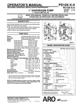
TYPICAL CROSS SECTION

PD02PĆXPage 8 of 8
DIMENSIONAL DATA
1/4 Ć 18 N.P.T.F. Ć 1 Outlet
www.arozone.com
Dimensions shown are for reference only. They are shown in inches and millimeters (mm).
11/16" (17 mm)
1Ć5/32" (30 mm)
SIDE VIEW
END VIEWS
1Ć5/32" (30 mm)
11/16" (17 mm)
5/16" (8 mm) SLOT
3/8 Ć 18 N.P.T.F. Ć 1 Inlet
1/4 Ć 18 P.T.F. Air Inlet
1/4 Ć 18 N.P.T.F. Ć 1 Outlet
1/4 Ć 18 P.T.F. Exhaust
3/8 Ć 18 N.P.T.F. Ć 1 Inlet
4Ć3/4" (121 mm)
5Ć1/2" (140 mm)
4Ć13/32"
(112 mm)
1Ć9/32"
(32 mm)
4Ć17/32"
(115 mm)
1Ć3/8"
(35 mm)
8Ć1/32" (205 mm)
6Ć1/2" (165 mm)
7Ć9/32" (185 mm)
5Ć5/8"
(143 mm)
A FULL SIZE VERSION OF THIS MANUAL IS AVAILABLE UPON REQUEST (PN 97999Ć681)
PN 97999Ć680
/