Page is loading ...

Handbook
Edition 04/2005 - Revision 04
Order no.: FDK-521H0723
SFIDK.PS.027.W4.02
SITRANS F M MAGFLO®®
®®
®
Electromagnetic flowmeters
Sensor types MAG 1100, MAG 3100, MAG 5100 W
Transmitter types MAG 5000, MAG 6000
s
[ ]
Technical Documentation (handbooks, instructions, manuals etc.) on the complete product
range SITRANS F can be found on the internet/intranet on the following links:
English: http://www4.ad.siemens.de/WW/view/en/10806951/133300

SFIDK.PS.027.W4.02
SITRANS F M MAGFLO®
Siemens Flow Instruments
range of electromagnetic
flowmeters
2
MAG 1100 MAG 1100 MAG 3100 MAG 3100 W MAG 5100 W
FOOD
Size [mm] DN 2-100 DN 10-100 DN 15-2000 DN 25-1200 DN 25-1200
Connection Flangeless Weld-in adapter, Flange Flange Flange
(Sandwich design) clamp adapter,
thread adapter
Pressure [bar] Max. 40 Max. 40 Max. 100 Max. 40 Max. 40
Temperature [°°
°°
°C] −20 to 200 −30 to 150 −40 to180 −10 to 95 −5 to 90
Liner Zirconium oxide Ceramic (Al2 O 3), Neoprene, EPDM, Neoprene and DN 25-40 &
(Zr02) PFA Teflon (PTFE), EPDM DN 350-1200
Ceramic (Al2 O3), Ebonite, hard elastomer
PFA Linatex®DN 50-300
composite elastomer
Electrodes Platinum Platinum AISI 316 Ti, AISI 316 Ti, AISI 316 Ti,
Hastelloy C276 Hastelloy Hastelloy C, PE electrodes PE electrodes
Platinum/Iridium,
Titanium,
Tantalum,
PE electrodes
Enclosure IP 67 IP 67 IP 67/IP 68 IP 67/IP 68 IP 67/IP 68
Ex-version EEx [ia] [ib] IIB T4-T6 EEx e ia IIC T3-T6
EEx d [ia] [ib] IIB T4-T6
MAG 5000 MAG 6000
Outputs 1 current output 1 current output
1digital output 1digital output
1 relay output 1 relay output
Flow direction Uni/bidirectional Uni/bidirectional
Communication Optional Add-on modules
HART®
Display 3 lines 3 lines
20 characters 20 characters
(optional without display) (optional without display)
Meter uncertainty ±0,5% o.r. ±0,25% o.r.
Enclosure IP 67, IP 20 IP 67, IP 20
Custody transfer PTB PTB
approval (cold water) OIML R75
OIML R117
Ex-version [EEx ia] IIC [EEx ia ib] IIB
Safety barrier 19" [EEx ia] IIC
Power supply 12-24 V AC/DC 12-24 V AC/DC
115-230 V AC 115-230 V AC
Batch No Yes
MAG 6000 Industry MAG 8000 W
Refer to Operating manual Operating manual
SFIDK.PS.026.E1.02 SFIDK.PS.026.D2.02

3
SITRANS F M MAGFLO®
SFIDK.PS.027.W4.02
1.1 Product introduction ................................................................................................................................................. 4
1.2 Mode of operation .................................................................................................................................................... 5
1.3 Pressure Equipment Directive 97/23ECs ................................................................................................................. 6
1.3.1 Exclusions ............................................................................................................................................................... 7
1.3.2 Product marking ....................................................................................................................................................... 7
2.1 Sensor MAG 1100 and MAG 1100 Ex ..................................................................................................................... 8
2.2 Sensor MAG 1100 FOOD ........................................................................................................................................ 9
2.3 Sensor MAG 3100, MAG 3100 Ex and MAG 3100 W ............................................................................................ 10
2.4 Sensor MAG 5100 W - updated 2005.10.21 .......................................................................................................... 12
2.5.1 Transmitter MAG 5000 (DN 6 to DN 1200) - updated 2005.06.13 .......................................................................... 13
2.5.2 Transmitter MAG 6000 - updated 2005.06.13 ........................................................................................................ 14
2.5.3 Safety barrier (ia/ib) DN ≤ 300 ............................................................................................................................... 15
2.5.4 Safety barrier (ia) DN ≥ 350 ................................................................................................................................... 15
2.5.5 Cleaning unit .......................................................................................................................................................... 15
2.6 Meter uncertainty - updated 2006.03.15 ............................................................................................................... 16
2.7 Output characteristics MAG 5000 and MAG 6000 ................................................................................................. 17
2.8.1 Sensor cables and conductivity of medium ........................................................................................................... 18
2.8.2 Minimum accept data for cable .............................................................................................................................. 18
2.9 HART® communication add-on module .................................................................................................................. 18
2.10 Cable data (Supplied by Siemens Flow Instruments) ............................................................................................ 18
3.1 Sizing table (DN 2 to DN 2000) .............................................................................................................................. 19
3.2.1 Minimum conductivity ............................................................................................................................................. 20
3.2.2 Liner selection guide .............................................................................................................................................. 20
3.2.3 Electrode selection guide ...................................................................................................................................... 20
3.3 Installation conditions ............................................................................................................................................ 20
3.4 Cleaning unit .......................................................................................................................................................... 24
3.5 Custody transfer approval ..................................................................................................................................... 25
3.6 Transmitter MAG 5000 CT, MAG 6000 CT Sealing .................................................................................................. 25
3.7 Ex survey according to Directive 94/9/EC (ATEX) ................................................................................................. 26
3.8 Approvals ............................................................................................................................................................... 27
4.1 Sensor MAG 1100 .................................................................................................................................................. 28
4.2 Sensor MAG 1100 FOOD ....................................................................................................................................... 29
4.3 Sensor MAG 5100 W - updated 2006.03.15 .......................................................................................................... 32
4.4 Sensor MAG 3100 and MAG 3100 W ..................................................................................................................... 34
4.5 Transmitter ............................................................................................................................................................. 35
5.1 Potential equalization ............................................................................................................................................. 37
5.2 Inlet protection MAG 3100 ..................................................................................................................................... 39
5.3 Cathodic protected piping ...................................................................................................................................... 39
6.1 Compact installation MAG 5000 and MAG 6000 .................................................................................................... 40
6.2.1 Add-on modules MAG 6000 only ............................................................................................................................ 42
6.2.2 Remote installation. At the sensor ......................................................................................................................... 42
6.2.3 Remote installation. Wall mounting ......................................................................................................................... 43
6.2.4 Remote installation. Transmitter in 19" insert ......................................................................................................... 45
6.2.5 Add-on modules MAG 6000 only ............................................................................................................................ 46
6.2.6 Installation in IP 66 wall mounting enclosure ......................................................................................................... 47
6.2.7 Installation in IP 65 panel mounting enclosure (front of panel) .............................................................................. 48
6.2.8 Installation into the back of a panel ...................................................................................................................... 49
6.3 Transmitter Safety barrier ...................................................................................................................................... 50
6.4 Transmitter Cleaning unit ........................................................................................................................................ 51
7.1 Transmitter MAG 5000 and MAG 6000 connection diagram ................................................................................... 52
7.2 Wiring diagram for transmitter and sensor ............................................................................................................. 53
8.1 Keypad and display layout ..................................................................................................................................... 57
8.2 Menu build-up ......................................................................................................................................................... 58
8.2.1 Password ............................................................................................................................................................... 58
8.3.1 MAG 5000 and MAG 6000 - Menu overview .......................................................................................................... 59
8.3.2 MAG 5000 CT and MAG 6000 CT - Menu overview ................................................................................................ 60
8.4.1 Basic settings ........................................................................................................................................................ 61
8.4.2 Outputs .................................................................................................................................................................. 62
8.4.3 Digital and relay outputs ........................................................................................................................................ 62
8.4.4 Relay outputs ......................................................................................................................................................... 63
8.4.5 External input ......................................................................................................................................................... 63
8.4.6 Sensor characteristics ........................................................................................................................................... 64
8.4.7 Reset mode ............................................................................................................................................................ 64
8.4.8 Service mode ......................................................................................................................................................... 65
8.4.9 Operator menu setup ............................................................................................................................................. 66
8.4.10 Product identity ..................................................................................................................................................... 67
8.4.11 Change password .................................................................................................................................................. 67
8.4.12 Language mode ..................................................................................................................................................... 68
8.4.13 HART® communication MAG 5000 HART or as add-on module .............................................................................. 68
8.5.1 Flow rate ................................................................................................................................................................ 69
8.5.2 Totalizer ................................................................................................................................................................. 69
8.5.3 Batch ..................................................................................................................................................................... 69
8.6.1 Settings available .................................................................................................................................................. 70
8.6.2 Dimension dependent factory settings MAG 5000 and MAG 6000 ........................................................................ 71
8.6.3 Dimension dependent batch and pulse output settings ......................................................................................... 71
8.6.4 MAG 5000 CT and MAG 6000 CT settings ............................................................................................................. 72
8.7.1 Error handling ......................................................................................................................................................... 73
8.7.2 List of error numbers ............................................................................................................................................. 74
9.1 Transmitter check list ............................................................................................................................................. 75
9.2 Trouble shooting MAG transmitter .......................................................................................................................... 76
9.3 Check list MAG sensor .......................................................................................................................................... 77
9.4 Coil resistance table .............................................................................................................................................. 78
10. Please look on our homepage http://www.siemens.com/flow under "Product Selector" ...................................... 79
2. Technical data
1. Product introduction
3. Project guidance
4. Dimensions and weight
6. Installation of transmitter
5. Installation of sensor
7. Electrical connection
8. Commissioning
10. Ordering
9. Service
Technical data
Sensor
Commissioning
Order-
ing
D & WInstallation of signal conv.
E. c. Project guidance

4
SITRANS F M MAGFLO®
SFIDK.PS.027.W4.02
All SITRANS F M MAGFLO® electromagnetic flowmeters feature a unique SENSORPROM®
memory unit which stores sensor calibration data and transmitter settings for the lifetime of the
product.
At commissioning the flowmeter commences measurement without any initial programming.
1.1
Product introduction
1. Product introduction
SITRANS F M MAGFLO® electromagnetic flowmeters offer reliable, precise and inexpensive
flow measurement on all electrically conductive liquids. Typical applications are found in all
industries. E.g.:
• Water sector: Potable water, treatment of chemicals, waste water and sludge.
• Food sector: Dairy products, beer, wine, soft-drinks and fruit juices.
• Chemical sector: Detergents, pharmaceuticals, acids and alkalies.
• Other sectors: District heating, paper pulp and mining slurries.
SITRANS F M MAGFLO® electromagnetic flowmeters are characterised by simplicity:
⇒Simple to install
⇒Simple to commission
⇒Simple to operate
⇒Simple to maintain
SITRANS F M MAGFLO® electromagnetic flowmeters are manufactured by Siemens Flow
Instruments A/S - one of the worlds leading makers of flowmeters.
The factory settings matching the sensor are stored
in the SENSORPROM® unit. Also customer specified
settings are downloaded to the SENSORPROM®
unit. Should the transmitter be replaced, the new
transmitter will upload all previous settings and
resume measurement without any need for re-
programming.
Furthermore, the "fingerprint" used in connection
with the Siemens Flow Instruments Verificator is
stored during the sensor calibration.
USM II "Plug & Play" add-on communication
modules.
USM II - the Universal Signal Module with "Plug &
Play" simplicity makes it easy to access and integrate
the flow measurement with almost any system. It
ensures the flowmeter will be easy to upgrade to new
communication platforms in the future, too.

5
SITRANS F M MAGFLO®
SFIDK.PS.027.W4.02
1. Product introduction
Ui = When an electrical conductor of length L is moved at velocity v, perpendicular to the lines of
flux through a magnetic field of strength B, the voltage Ui is induced at the ends of the conductor
Ui = L x B x v
Ui= Induced voltage
L = Conductor length = Inner pipe diameter = k1
B = Magnetic field strength = k2
v = Velocity of conductor (media)
k=k
1 x k2
Ui = k x v, the electrode signal is directly proportional to the fluid velocity
SENSOR
The sensor converts the flow into an electrical voltage (Ui) proportional to the velocity of the flow.
The sensor is built up of a stainless steel pipe, 2 coils, electrodes, an isolating liner, housing and
where applicable, connecting flanges.
TRANSMITTER
The transmitter consists of a number of function blocks which convert the sensor voltage into flow
readings.
Power supply
2 different types of power supply are available. A 12 - 24 V AC/DC and a 115 - 230 V AC switch mode
type.
Coil current module generates a pulsating magnetizing current that drives the coils in the sensor.
The current is permanently monitored and corrected. Errors or cable faults are registered by the self-
monitoring circuit.
Input circuit amplifies the flow proportional signal from the electrodes. The input impedance is
extremely high: >1014 Ω which allows flow measurements on fluids with conductivities as low as
1 mS/cm. Measuring errors due to cable capacitance are eliminated due to active cable screening.
Digital signal processor converts the analog flow signal to a digital signal and suppresses
electrode noise through a digital filter. Inaccuracies in the transmitter as a result of long-term drift
and temperature drift are monitored and continuously compensated for via the self-monitoring
circuit. The analog to digital conversion takes place in an ultra low noise ASIC with 23 bit signal
resolution. This has eliminated the need for range switching. The dynamic range of the transmitter
is therefore unsurpassed with a turn down ratio of minimum 3000:1.
CAN communication
The transmitter operates internal via an internal CAN communication bus. Signals are transferred
to/from a signal conditioner to the display module, internal/external option modules and the dialog
module.
Dialog module
The display unit consists of a 3-line display and a 6-key keypad. The display shows a flow rate or
a totalizer value as a primary reading.
Output module converts flow data to an analog, a digital and a relay output. The outputs are
galvanically isolated and can be individually set to suit a particular application.
1.2
Mode of operation
The flow measuring principle is based on Faraday’s law of electromagnetic induction. The
flowmeter consists of a sensor type MAG 1100, MAG 3100 or MAG 5100 W and a transmitter type
MAG 5000 or 6000.

6
SITRANS F M MAGFLO®
SFIDK.PS.027.W4.02
1. Product introduction
1.3
Pressure Equipment
Directive 97/23ECs
Flange PN 6 PN 10 PN 16 PN 25 PN 40 PN 64 PN 100 150 lb 300 lb AWWA
mm
25 N/A N/A N/A N/A SEP N/A SEP SEP SEP N/A
40 N/A N/A N/A N/A SEP N/A PED SEP SEP N/A
50 N/A N/A N/A N/A SEP PED PED SEP PED* N/A
65 SEP N/A SEP N/A PED PED PED SEP PED* N/A
80 SEP N/A SEP N/A PED PED PED SEP PED* N/A
100 SEP N/A SEP N/A PED PED PED SEP PED* N/A
125 SEP N/A SEP N/A PED PED PED PED* PED* N/A
150 SEP N/A PED N/A PED PED PED PED* PED* N/A
200 SEP SEP PED PED PED PED PED PED* PED* N/A
250 SEP LVD PED PED PED PED PED PED* PED* N/A
300 SEP LVD PED PED PED PED PED PED* PED* N/A
350 LVD LVD PED PED PED PED PED PED* PED* N/A
400 LVD LVD PED PED PED PED N/A PED* PED* N/A
450 LVD LVD PED PED PED N/A N/A PED* PED* N/A
500 LVD LVD PED PED PED N/A N/A PED* PED* N/A
600 LVD LVD PED PED PED N/A N/A PED* PED* N/A
700 LVD LVD PED* N/A N/A N/A N/A N/A N/A PED*
750 N/A N/A N/A N/A N/A N/A N/A N/A N/A PED*
800 LVD LVD PED* N/A N/A N/A N/A N/A N/A PED*
900 LVD LVD PED* N/A N/A N/A N/A N/A N/A PED*
1000 LVD LVD PED* N/A N/A N/A N/A N/A N/A PED*
1050 N/A N/A N/A N/A N/A N/A N/A N/A N/A PED*
1100 LVD LVD PED* N/A N/A N/A N/A N/A N/A PED*
1200 LVD LVD PED* N/A N/A N/A N/A N/A N/A PED*
1400 LVD LVD PED* N/A N/A N/A N/A N/A N/A PED*
1500 LVD LVD PED* N/A N/A N/A N/A N/A N/A PED*
1600 LVD LVD PED* N/A N/A N/A N/A N/A N/A PED*
1800 LVD LVD PED* N/A N/A N/A N/A N/A N/A PED*
2000 LVD LVD PED* N/A N/A N/A N/A N/A PED*
MAG 3100 & MAG 3100 W
From May 30th 2002 the "Pressure Equipment Directive" is mandatory for all pressure equipment
sold within the EU and EFTA.
The approach that Siemens Flow Instruments has taken is outlined in the tables below.
MAG 5100 W
Flange PN 10 PN 16 PN 40 150 lb 300 lb
mm
25 N/A N/A SEP SEP N/A
40 N/A N/A SEP SEP N/A
50 N/A SEP N/A SEP N/A
65 N/A SEP N/A SEP N/A
80 N/A SEP N/A SEP N/A
100 N/A SEP N/A SEP N/A
125 N/A SEP N/A PED* N/A
150 N/A PED N/A PED* N/A
200 SEP PED N/A PED* N/A
250 LVD PED N/A PED* N/A
300 LVD PED N/A PED* N/A
350 LVD PED N/A PED* N/A
400 LVD PED N/A PED* N/A
450 LVD PED N/A PED* N/A
500 LVD PED N/A PED* N/A
600 LVD PED N/A PED* N/A
700 LVD PED* N/A N/A PED*
750 N/A N/A N/A N/A PED*
800 LVD PED* N/A N/A PED*
900 LVD PED* N/A N/A PED*
1000 LVD PED* N/A N/A PED*
1050 N/A N/A N/A N/A PED*
1100 N/A N/A N/A N/A PED*
1200 LVD PED* N/A N/A PED*

7
SITRANS F M MAGFLO®
SFIDK.PS.027.W4.02
MAG 3100 high temperature PTFE
Flange PN 6 PN 10 PN 16 PN 25 PN 40 150 lb 300 lb
mm
15 N/A N/A N/A N/A SEP SEP SEP
25 N/A N/A N/A N/A SEP SEP SEP
40 N/A N/A N/A N/A PED LVD PED*
50 N/A N/A N/A N/A PED PED* PED*
65 LVD N/A PED N/A PED PED* PED*
80 LVD N/A PED N/A PED PED* PED*
100 LVD N/A PED N/A PED PED* PED*
125 PED N/A PED N/A PED PED* PED*
150 PED N/A PED N/A PED PED* PED*
200 PED PED PED PED PED PED* PED*
250 PED PED PED PED PED PED* PED*
300 PED PED PED PED PED PED* PED*
350 PED PED PED PED PED PED* PED*
400 PED PED PED PED PED PED* N/A
450 PED PED PED PED PED PED* N/A
500 PED PED PED PED PED PED* N/A
600 PED PED PED PED PED*
1. Product introduction
MAG 1100
Flange Ceramic Ceramic Ceramic Ceramic Ceramic PFA PFA PFA
mm 150°200°Ex Ex-d FOOD Ex FOOD
2SEP N/A N/A N/A N/A N/A N/A N/A
3SEP N/A N/A N/A N/A N/A N/A N/A
6SEP N/A SEP SEP N/A N/A N/A N/A
10 SEP N/A SEP SEP SEP SEP SEP SEP
15 SEP SEP SEP SEP SEP SEP SEP SEP
25 SEP SEP SEP SEP SEP SEP SEP SEP
40 PED PED PED PED PED LVD LVD LVD
50 PED PED PED PED PED PED PED PED
65 PED N/A PED PED PED PED PED PED
80 PED PED PED PED PED PED PED PED
100 PED PED PED PED PED PED PED PED
The key to the above tables is as follows.
PED Product covered by PED and only available as fully PED conforming
PED* Product covered by PED but available as either conforming or non conforming to PED
SEP Excluded from PED under Sound Engineering Practice
LVD Excluded from PED under the Low Voltage Directive
1.3.1
Exclusions
All products sold outside of EU and EFTA are excluded from the directive, also products sold into
certain market sectors are also excluded. These include
1) Meters used in networks for the supply, distribution and discharge of water.
2) Meters used in pipelines for the conveyance of any fluid from offshore to onshore.
3) Meters used in the extraction of petroleum or gas, including christmas tree and manifold
equipment.
4) Any meter mounted on a ship or mobile offshore platform.
1.3.2
Product marking
All meters will now carry either a CE mark or a CE mark followed by 0086
CE0086: This indicates that the product conforms to PED 97/23/EC, LVD 73/23/EEC + Amendment
93/68/EEC & EMC 89/336 EEC
CE: This indicates that the product conforms to LVD 73/23/EEC + Amendment 93/68/EEC &
EMC 89/336 EEC

8SFIDK.PS.027.W4.02
2. Technical data
Technical data
SITRANS F M MAGFLO®
Type Flangeless sensor (Sandwich design)
Nominal size
mm
DN 2,3,6,10,15,25,40,50,65,80,100 DN 10,15,25,40,50,65,80,100 DN 2,3,6,10,15,25,40,50,65,80,100
Operating pressure DN 2-65: 40 bar, DN 80: 37.5 bar, DN 2-65: 40 bar, DN 80: 37.5 bar,
DN 100: 30 bar 20 bar DN 100: 30 bar
Vacuum: 1 × 10⁻⁶ bar Vacuum: 0.02 bar Vacuum: 1 × 10⁻⁶ bar
Temperature of
PFA
−30°C to +130°C
medium
Ceramic
−20°C to +150°C−20°C to +120°C
High temp.
−20°C to +200°C (DN 6-100) Suitable for steam sterilization at 150°C
Temperature shock (Duration > 1 min.): Max. ±100°C momentarily (Duration > 1 min.):
(Ceramic liner) DN 2, 3: Max. ∆T ≤ 20°C/min. DN 2, 3: Max. ∆T ≤ 20°C/min.
DN 6,10,15,25: Max. ∆T ≤ 15°C/min. DN 6,10,15,25: Max. ∆T ≤ 15°C/min.
DN 40, 50, 65: Max. ∆T ≤ 10°C/min. DN 40, 50, 65: Max. ∆T ≤ 10°C/min.
DN 80, 100: Max. ∆T ≤ 5°C/min. DN 80, 100: Max. ∆T ≤ 5°C/min.
(Duration ≤ 1 min., (Duration ≤ 1 min.,
followed by 10 min. rest): followed by 10 min. rest):
DN 2, 3: Max. ∆T ≤ 100°C DN 2, 3: Max. ∆T ≤ 100°C
DN 6, 10, 15, 25: Max. ∆T ≤ 80°C DN 6, 10, 15, 25: Max. ∆T ≤ 80°C
DN 40, 50, 65: Max. ∆T ≤ 70°C DN 40, 50, 65: Max. ∆T ≤ 70°C
DN 80, 100: Max. ∆T ≤ 60°C DN 80, 100: Max. ∆T ≤ 60°C
Ambient temperature Remote transmitter: −40°C to +100°C
Compact transmitter: −20°C to +50°C
Liner DN 2 - 3 Zirconium oxide ZrO2Zirconium oxide ZrO2
DN 6 - 100 Aluminium oxide Al2O3 (ceramics) Reinforced PFA (Teflon) Aluminium oxide Al2O3 (ceramics)
Electrodes DN 2 - 3 Platinum sintered Platinum sintered
DN 6 - 100 Platinum with gold/titanium brazing Hastelloy C-276 Platinum with gold/titanium brazing
alloy alloy
Enclosure Stainless steel AISI 316 L (1.4404) Stainless steel AISI 316 (1.4404) Stainless steel AISI 316 L (1.4404)
Terminal box
Standard
Fibre glass-reinforced polyamide Fibre glass-reinforced polyamide Stainless steel AISI 316 (1.4436)
(not compact) High temp.
Stainless steel AISI 316 (1.4436) Stainless steel AISI 316 L (1.4436)
Fixing studs Stainless steel AISI 304 (1.4301) Stainless steel AISI 304 (1.4301)
Number and size to EN 1092-1:2001 Number and size to EN 1092-
1:2001
Mating flanges EN 1092-1:2001, ANSI B16.5 class 150 and 300 or equivalent EN 1092-1:2001, ANSI B16.5
class 150 and 300 or equivalent
Option
DN 2-10: ½" pipe connection adapters thread: G½" tappered ISO 7-1 or ½" NPT thread
Gaskets
Standard
EPDM (max. 150°C, PN 40) EPDM (max. 150°C, PN 40)
Option
Graphite (max. 200°C, PN 40) Graphite (max. 200°C, PN 40)
Option
PTFE (max. 130°C, PN 25) PTFE (max. 130°C, PN 25)
Cable entries 4 Pg 13.5
Enclosure rating
Standard
IP 67 to EN 60529 (NEMA 4x) (1 m w.g for 30 min.)
Option
IP 68 to EN 60529 (NEMA 6) (10 m w.g. cont.)
Mechanical load (vibration) 18-1000 Hz random, 3.17 G rms in all directions to EN 60068-2-36 18-1000 Hz random in all directions
to EN 60068-2-36
Sensor: 3.17 G/Compact Ex-d: 1.14 G
Test pressure 80 bar (2 × PN) 40 bar (2 × PN) 80 bar (2 × PN)
Approvals 3A EEx ia/ib IIB T4-T6/
DEMKO, No. 97D.121909X
EEx de [ia/ib] IIB T4-T6/
DEMKO 94C.115327X
Excitation frequency DN 2-65: 12.5 Hz DN 10-65: 12.5 Hz DN 2-65: 6.25 Hz
DN 80-100: 6.25 Hz DN 80-100: 6.25 Hz DN 80-100: 3.125 Hz
Conforms to PED, LVT, EMC PED - 97/23EC, LVD - 73/23 EEC + amendment 93/68/EEC, EMC - 89/336 EEX
2. Technical data
2.1 Sensor MAG 1100 and MAG 1100 Ex
MAG 1100 MAG 1100 PFA MAG 1100 Ex & Ex-d
MAG 1100 and MAG 1100 Ex

9
SITRANS F M MAGFLO®
SFIDK.PS.027.W4.02
2. Technical data
Technical data
Adapter Stainless steel AISI 316 Pressure
Pipe connection/ Adapter for direct welding into dairy pipe:
Operating
Tri-Clover
ISO 2037, DIN 11850, SMS 3008, BS 4825-1
pressure DN 10, 15, 25, 40, 50, 65, 80 PN 40
DN 100 PN 25
Clamp adapter:
Tri-Clamp
ISO 2852, DIN 32676, SMS 3016, BS 4825-3
DN 10, 15, 25, 40, 50 PN 16
DN 65, 80, 100 PN 10
Thread adapter:
DIN 11851: DN 10, 15, 25, 40 PN 40
DN 50, 65, 80, 100 PN 25
ISO 2853, SS 3351, BS 4825-4: DN 10, 15, 25, 40, 50, 65, 80 PN 16
SMS 1145: DN 25, 40, 50, 65, 80 PN 6
Gasket
Standard
EPDM (−20 °C to 150 °C)
Option
NBR (−20 °C to 100 °C)
Clamp Stainless steel AISI 304, ISO 2852
Type Hygienic sensor
Nominal size
mm
DN 10, 15, 25, 40, 50, 65, 80, 100
Process connection Hygienic adapters available for:
♦ Direct welding into dairy pipe ♦ Clamp fitting ♦ Threaded fitting
Operating pressure DN 10-65: 40 bar, DN 80: 37.5 bar, DN 100: 30 bar 20 bar
Vacuum
1 × 10⁻⁶ bar 0.02 bar
Temperature of medium −20°C to +150°C−30°C to +130°C
Suitable for steam sterilization Suitable for steam sterilization at 150°C
Temperature shock (Duration > 1 min.): Max. ±100°C momentarily
DN 10, 15, 25 Max. ∆T ≤ 15°C/min.
DN 40, 50, 65 Max. ∆T ≤ 10°C/min.
DN 80, 100 Max. ∆T ≤ 5°C/min.
(Duration ≤ 1 min., followed by 10 min. rest):
DN 10, 15, 25 Max. ∆T ≤ 80°C
DN 40, 50, 65 Max. ∆T ≤ 70°C
DN 80, 100 Max. ∆T ≤ 60°C
Ambient temperature Remote transmitter: −40°C to +100°C Remote transmitter: −40°C to +100°C
Compact transmitter: −20°C to +50°C Compact transmitter: −20°C to +50°C
Liner Aluminium oxide Al2O3 (ceramic) Reinforced PFA (Teflon)
Electrodes Platinum with gold/titanium brazing alloy Hastelloy C-276
Enclosure Stainless steel AISI 316 L (1.4404) Stainless steel AISI 316 L (1.4404)
Terminal box
Standard
Fibre glass-reinforced polyamide Fibre glass-reinforced polyamide
(not compact) Option
Stainless steel AISI 316 (1.4436) Stainless steel AISI 316 (1.4436)
Cable entries 4 Pg 13.5 4 Pg 13.5
Enclosure rating
Standard
IP 67 to EN 60529 (NEMA 4x) (1 m w.g for 30 min.) IP 67 to EN 60529 (NEMA 4x) (1 m w.g for 30 min.)
Option
IP 68 to EN 60529 (NEMA 6) (10 m w.g. cont.) IP 68 to EN 60529 (NEMA 6) (10 m w.g. cont.)
Mechanical load (vibration) 18-1000 Hz random, 3.17 G rms in all directions 18-1000 Hz random, 3.17 G rms in all directions
to EN 60068-2-36 to EN 60068-2-36
Test pressure 80 bar (2 × PN) 40 bar (2 × PN)
Approvals 3A, EHEDG 3A
Excitation frequency DN 10-65: 12.5 Hz DN 10-65: 12.5 Hz
DN 80-100: 6.25 Hz DN 80-100: 6.25 Hz
Conforms to PED, LVT, EMC PED - 97/23EC, LVD - 73/23 EEC + amendment 93/68/EEC, EMC - 89/336 EEX
2.2 Sensor MAG 1100 FOOD
MAG 1100 FOOD MAG 1100 FOOD PFA
Accessories
MAG 1100 FOOD
Note
When combined sensor and adapter, the working pressure is the lower rated of the pair.
MAG 1100 FOOD

10 SFIDK.PS.027.W4.02
2. Technical data
Technical data
SITRANS F M MAGFLO®
Type Sensor with flanges Sensor with flanges Sensor with flanges
Nominal size
mm
DN 15-2000 DN 15-2000 / 15-300 DN 25-1200
Temperature of medium Temperature classification
Liner:
T3 + T4 T5 T6
Neoprene (standard) 0 to 70°C 0 to 70°C 0 to 70°C 0 to 70°C 0 to 70°C
EPDM1)−10 to 95°C−10 to 95°C−10 to 90°C−10-75°C−10 to 95°C
Linatex® rubber −40 to 70°C2)−20 to 70°C−20 to 70°C−20 to 70°C
Ebonite1) 0 to 95°C 0 to 95°C 0 to 90°C 0 to 75°C
PTFE −20 to 100°C−20 to 100°C−20 to 90°C−20 to 75°C
PTFE high temperature −20 to 180°C
(remote only)
Ambient temperature
Remote transmitter −40°C to 100°C−20°C to 50°C−40°C to 100°C
Compact transmitter −20°C to 50°C−20°C to 50°C−20°C to 50°C
Operating pressure3) [[
[[
[abs.bar]]
]]
]
Liner:
Neoprene 0.01 to 100 bar 0.01 to 100 bar 0.01 to 40 bar
EPDM 0.01 to 40 bar 0.01 to 40 bar 0.01 to 40 bar
Linatex®0.01 to 40 bar 0.01 to 40 bar
Ebonite 0.01 to 100 bar 0.01 to 100 bar
PTFE teflon:
DN 15 to 600 Max. 100°C: 0.3 to 50 bar 0.3 to 40 bar
DN 15 to 300 Max. 180°C: 0.6 to 50 bar
Excitation frequency DN 15 - 65: 12.5 Hz DN 15 - 65: 6.25 Hz All sizes 3.125 Hz
DN 80 - 150: 6.25 Hz DN 80/100: 3.125 Hz
DN 200 - 1200: 3.125 Hz DN 125 - 300: 1.5625 Hz
DN 1400 - 2000: 1.5625 Hz DN 350 - 1200: 3.125 Hz
Enclosure rating
Standard
IP 67 to EN 60529 (NEMA 4x) (1 m w.g for 30 min.)
Option
IP 68 to EN 60529 (NEMA 6) (10 m w.g. cont.)
Cable entries 4 Pg 13.5
Mechanical load 18-1000 Hz random, 3.17 G rms in all directions to EN 60068-2-36
Test pressure 1.5 × PN
Conforms to PED, LVT, EMC PED - 97/23EC, LVD - 73/23 EEC + amendment 93/68/EEC, EMC - 89/336 EEX
2.3 Sensor MAG 3100, MAG 3100 Ex and MAG 3100 W
MAG 3100 MAG 3100 Ex / Ex-d MAG 3100 W
1) With WRAS drinking water approval, approved to BS 6920 by WRC (Water Research Council, UK)
2) For temperature below −20°C AISI 304 or 316 flanges must be used
3) Maximum operating pressure decreases with increasing operating temperature and with stainless steel flanges
MAG 3100, MAG 3100 Ex and MAG 3100 W

11
SITRANS F M MAGFLO®
SFIDK.PS.027.W4.02
2. Technical data
Technical data
Flanges
Standard
DN 15-50: PN 40 DN 25-50: PN 40
EN 1092-1:20011)DN 65-150: PN 16 DN 65-150: PN 16
Raised face DN 200-1000: PN 10 DN 200-1200: PN 10
DN 1100 -2000: PN 6
Option
DN 65-1000: PN 6 DN 200-600: PN 16
DN 1200-2000: PN 10
DN 200-2000: PN 16
DN 200-600: PN 25
DN 65-600: PN 40
DN 50-400 PN 63
DN 25-350 PN 100
ANSI B 16.5 3/4"-24": Class 150 (20 bar) 3/4"-24": Class 150 (20 bar)
(∼BS 1560) 3/4"-24": Class 300 (50 bar)
AS 2129 3/4"-48": Table D (7 bar) / E (14 bar)
AS 4087 Class 14 (DN 50 - 1200, 14 bar)
Class 21 (DN 50 - 600, 21 bar)
Class 35 (DN 50 - 600, 35 bar)
AWWA C-207 28"-78": Class D (10 bar) 28"-48": Class D (10 bar)
Electrodes
Standard
AISI 316 Ti (1.4571) AISI 316 Ti (1.4571)
Option
Hastelloy C-276, Platinum / Iridium, Titanium,
AISI 316 Ti Ceramic Coated, Tantalum
PE - electrodes
Standard
As measuring electrodes (except PTFE) AISI 316 Ti (1.4571)
Measuring pipe
Standard
AISI 304 (1.4301) AISI 304 (1.4301)
Option
AISI 316 L (1.4436)
Flange and
Standard
Carbon steel Carbon steel
housing material Corrosion-resistant two-component coating (min. 150 µm) Corrosion-resistant two-compo-
nent coating (min. 150 µm)
Option
AISI 304 (1.4301) flanges and carbon steel housing. Coating as above
Option
AISI 316 L (1.4404) flanges and housing
Colour Siemens 700 light basic Siemens 700 light basic
Ex-approval
Remote
DN 15-300 EEx d [ia] [ib] IIB T4-T6
DN 350-2000 EEx e ia IIC T3-T6
Compact
EEx d e [ia] ia IIB T6
MAG 6000 I Ex-d
Conforms to PED, LVT, EMC PED - 97/23EC, LVD - 73/23 EEC + amendment 93/68/EEC, EMC - 89/336 EEX
2.3 Sensor MAG 3100, MAG 3100 Ex and MAG 3100 W
(continued)
MAG 3100 MAG 3100 Ex / Ex-d MAG 3100 W
MAG 3100, MAG 3100 Ex and MAG 3100 W
1) EN 1092-1, DIN 2501 & BS 4504 have the same mating dimensions

12 SFIDK.PS.027.W4.02
2. Technical data
Technical data
SITRANS F M MAGFLO®
Type Sensor with flanges
Design Straight Coned 1 DN reduction Straight
Nominal size
mm
25-40 50-300 350-1200
Liner Hard elastomer Composite elastomer Hard elastomer
(hard rubber)3) (hard & soft rubber)3) (hard rubber)3)
Liner approvals WRc WRc WRc
Medium temperature −5 to 70°C1)
Ambient temperature
Remote transmitter −40 to 100°C
Compact transmitter −20 to 50°C
Operating pressure 0.01 to 40 bar 0.03 to 20 bar 0.01 to 16 bar
Excitation frequency 12.5 Hz 50-65 mm: 12.5 Hz 3.125 Hz
80-150 mm: 6.25 Hz
200-300 mm: 3.125 Hz
Enclosure rating
Standard
IP 67 to EN 60529 1 m w.g. for 30 minutes
Option
IP 68 to EN 60529 10 m w.g. continuously
Cable entries 4 Pg 13.5
Mechanical load 18-1000 Hz random, 3.17 G rms in all directions to EN 60068-2-36
Test pressure 1.5 × nominal pressure
Flanges
EN 1092-1
Standard
PN 40 50-150 mm: PN 16 PN 10
200-300 mm: PN 10
Option
200-300 mm: PN 16 PN 16
ANSI B16.5
Standard
Class 150 lb Class 150 lb 14"-24": Class 150 lb
AWWA C-207 Standard 28"-48": Class D
Pressure drop at 3 m/sec. As straight pipe Max. 25 mbar As straight pipe
Electrodes AISI 316 Ti (1.4571)
PE/grounding electrodes
Standard
AISI 316 Ti (1.4571)
Measuring pipe/meter body AISI 304 (1.4301) Composite elastomer AISI 304 (1.4301)
Flanges Carbon steel
Housing Carbon steel
Surface finish Two component epoxy Polyester powder coat Two component epoxy
min. 150 microns min. 100 microns min. 150 microns
Colour Siemens 700 light basic
Approvals
Conforms to
PED - 97/23EC, LVD - 73/23 EEC + amendment 93/68/EEC, EMC - 89/336 EEX2)
2.4 Sensor MAG 5100 W
1)Peak temperature up to +90°C (194°F) in periods < 1 hour
2) For sizes greater than 600 mm PED conformity is available as a cost added option, the basic unit will only carry the LVD (Low Voltage Directive)
and EMC approval.
3) Nitrile, NBR
MAG 5100 W
- this page has been updated 2005.10.21

13
SITRANS F M MAGFLO®
SFIDK.PS.027.W4.02
2. Technical data
Technical data
Current output
Current 0-20 mA, 4-20 mA or 4-20 mA + alarm
Load < 800 ohm
Time constant 0.1-30 s adjustable
Digital output
Frequency 0-10 kHz, 50% duty cycle
Time constant 0.1-30 s adjustable
Active 24 V DC, 30 mA, 1 KΩ ≤ Rload ≤ 10 KΩ, short-circuit-protected
Passive 3-30 V DC, max. 110 mA, 200 Ω ≤ Rload ≤ 10 KΩ
Relay Time constant Changeover relay, time constant same as current time constant
Load 42 V AC/2 A, 24 V DC/1A
Digital input 11-30 V DC, Ri = 4.4 KΩ
Activation time 50 ms
Current I11 V DC = 2.5 mA, I30 V DC = 7 mA
Functions Flow rate, 2 totalizers, low flow cut-off, empty pipe cut-off 1), flow direction, error system,
operating time, uni/bidirectional flow, limit switches, pulse output, control for cleaning unit
Galvanic isolation All inputs and outputs are galvanically isolated
Cut-off Low flow 0-9.9% of maximum flow
Empty pipe Detection of empty pipe, special cable required in separate mounted installation
Totalizer Two eight-digit counters for forward, net or reverse flow
Display Background illumination with alphanumerical text, 3 × 20 characters to indicate flow rate, totalized
values, settings and faults
Reverse flow indicated by negative sign
Time constant Time constant as current output time constant
Zero point adjustment Automatic
Electrode input impedance > 1 x 10¹⁴ Ω
Excitation frequency Sensor size depending pulsating DC current (125 mA)
Ambient temperature Display version during operation: −20 to +50°C
Blind version during operation: −20 to +60°C
During storage: −40 to +70°C (RH max. 95%)
Custody transfer approval PTB
MAG 5000 CT (cold water)
Communication
Standard
Without serial communication
Optional
HART®
Compact
Enclosure material Fibre glass-reinforced polyamide
Enclosure rating IP 67 to EN 60529 and DIN 40050 (1 m w.g. for 30 minutes)
Mechanical load 18-1000 Hz random, 3.17 G rms in all directions to EN 60068-2-36
19" insert
Enclosure material Standard 19" insert of aluminium/steel (DIN 41494)
Width: 21 TE
Height: 3 HE
Enclosure rating IP 20 to EN 60529 and DIN 40050
Mechanical load Version: 1 G, 1-800 Hz sinusoidal in all directions to EN 60068-2-36
EMC performance Emission: EN 50081-1 (Light industry)
Immunity: EN 50082-2 (Industry)
Supply voltage 115-230 V AC +10% to −15%, 50-60 Hz
11-30 V DC or 11-24 V AC
Power consumption 230 V AC: 17 VA
24 V DC: 9 W, IN = 380 mA, IST = 8 A (30 ms)
12 V DC: 11 W, IN = 920 mA, IST = 4 A (250 ms)
2.5.1 Transmitter MAG 5000 (DN 2 to DN 1200)
Accuracy 0.5%
MAG 5000 and MAG 5000 CT
1) Not remote Ex, not DN 2, 3
6.221
99.19
- this page has been updated 2005.06.13

14 SFIDK.PS.027.W4.02
2. Technical data
Technical data
SITRANS F M MAGFLO®
Current output
Current 0-20 mA, 4-20 mA or 4-20 mA + alarm
Load < 800 ohm
Time constant 0.1-30 s adjustable
Digital output
Frequency 0-10 kHz, 50% duty cycle
Time constant 0.1-30 s adjustable
Active 24 V DC, 30 mA, 1 KΩ ≤ Rload ≤ 10 KΩ, short-circuit-protected
Passive 3-30 V DC, max. 110 mA, 200 Ω ≤ Rload ≤ 10 KΩ
Relay Time constant Changeover relay, time constant same as current time constant
Load 42 V AC/2 A, 24 V DC/1A
Digital input 11-30 V DC, Ri = 4.4 KΩ
Activation time 50 ms
Current I11 V DC = 2.5 mA, I30 V DC = 7 mA
Functions Flow rate, 2 totalizers, low flow cut-off, empty pipe cut-off 1), flow direction, error system,
operating time, uni/bidirectional flow, limit switches, pulse output, control for cleaning unit
and batch
Galvanic isolation All inputs and outputs are galvanically isolated
Cut-off Low flow 0-9.9% of maximum flow
Empty pipe Detection of empty pipe, special cable required in separate mounted installation
Totalizer Two eight-digit counters for forward, net or reverse flow
Display Background illumination with alphanumerical text, 3 × 20 characters to indicate flow rate, totalized
values, settings and faults
Reverse flow indicated by negative sign
Time constant Time constant as current output time constant
Zero point adjustment Automatic
Electrode input impedance > 1 x 10¹⁴ Ω
Excitation frequency Sensor size depending pulsating DC current (125 mA)
Ambient temperature Display version during operation: −20 to +50°C
Blind version during operation: −20 to +60°C
During storage: −40 to +70°C (RH max. 95%)
Custody transfer approval PTB DANAK OIML R75 DANAK OIML R117
MAG 6000 CT (cold water) (hot water) (cold water/milk, beer etc.)
Communication
Standard
Prepared for client mounted add-on modules
Add-on
HART, Profibus PA & DP, Modbus RTU, CANopen, DeviceNet
Compact
Enclosure material Fibre glass-reinforced polyamide
Enclosure rating IP 67 to EN 60529 and DIN 40050 (1 m w.g. for 30 minutes)
Mechanicalload 18-1000 Hz random, 3.17 G rms in all directions to EN 60068-2-36
19" insert
Enclosure material Standard 19" insert of aluminium/steel (DIN 41494)
Width: 21 TE
Height: 3 HE
Enclosure rating IP 20 to EN 60529 and DIN 40050
Mechanical load Version: 1 G, 1-800 Hz sinusoidal in all directions to EN 60068-2-36
EMC performance Emission: EN 50081-1 (Light industry)
Immunity: EN 50082-2 (Industry)
Supply voltage 115-230 V AC +10% to −15%, 50-60 Hz
11-30 V DC or 11-24 V AC
Power consumption 230 V AC: 17 VA
24 V DC: 9 W, IN = 380 mA, IST = 8A (30 ms)
12 V DC: 11 W, IN = 920 mA, IST = 4A (250 ms)
2.5.2 Transmitter MAG 6000
Accuracy 0.25%
MAG 6000 and MAG 6000 CT
6.221
99.19
1) Not remote Ex, not DN 2, 3
- this page has been updated 2005.06.13

15
SITRANS F M MAGFLO®
SFIDK.PS.027.W4.02
2. Technical data
Technical data
Safety barrier & cleaning unit
Application As combined unit with MAG 6000 only and MAG 1100 Ex/3100 Ex in the size
range DN 6-300
Ex approval [EEx ia/ib] IIB
Cable parameter Group Capacity in µF Inductance in mH
Electrode cable IIB ≤ 31 ≤ 80
Coil cable IIB ≤ 0.5 ≤ 8
Ambient temperature During operation: −20 to +50°C
During storage: −20 to +70°C
19" insert
Enclosure material Standard 19" insert in aluminium/steel (DIN 41494)
Width: 21 TE
Height: 3 HE
Enclosure rating IP 20 to EN 60529 and DIN 40050
Mechanical load 1 G, 1-800 Hz sinusoidal in all directions to EN 60068-2-36
EMC performance
Emission EN 50081-1 (Light industry)
Immunity EN 50082-2 (Industry)
2.5.3
Safety barrier (ia/ib)
DN ≤≤
≤≤
≤ 300
Application For use with MAG 5000/6000 19 insert and MAG 3100 Ex in the size
range DN 350-2000
Ex approval [EEx ia] IIC
Cable parameter Group Capacity in µF Inductance in mH
IIC ≤ 4.1 ≤ 1.5
IIB ≤ 45 ≤ 87
IIA ≤ 45 ≤ 87
Ambient temperature During operation: −20 to +50°C
During storage: −20 to +70°C
19" insert
Enclosure material Standard 19" insert in aluminium/steel (DIN 41494)
Width: 21 TE
Height: 3 HE
Enclosure rating IP 20 to EN 60529 and DIN 40050
Mechanical load 1 G, 1-800 Hz sinusoidal in all directions to EN 60068-2-36
EMC performance
Emission EN 50081-1 (Light industry)
Immunity EN 50082-2 (Industry)
2.5.4
Safety barrier (ia)
DN ≥≥
≥≥
≥ 350
Application For use together with MAG 5000 and 6000 19" insert to clean the electrodes
on MAG 1100, MAG 3100 or MAG 5100 W.
NB Must not be used with intrinsically safe systems
Cleaning voltage
(unloaded)
AC cleaning 60 V AC
DC cleaning 30 V DC
Cleaning period 60 sec. + 60 sec. pause period
Relay Switch relay activated when cleaning is in progress
Load 42 V/2 A
Operation
Automatic Yes
Manual No
Indicator lamps LEDs: "ON" and "CLEANING"
Supply voltage and 115-230 V AC +10% to −15%, 50-60 Hz, 7 VA cleaning, 5 VA stand by
power consumption
Ambient temperature During operation: −20 to +50°C
During storage: −20 to +70°C
19" insert
Enclosure material Standard 19" insert in aluminium/steel (DIN 41494)
Width: 21 TE
Height: 3 HE
Enclosure rating IP 20 to EN 60529 and DIN 40050
Mechanical load 1 G, 1-800 Hz sinusoidal in all directions to EN 60068-2-36
2.5.5
Cleaning unit

16 SFIDK.PS.027.W4.02
2. Technical data
Technical data
SITRANS F M MAGFLO®
MAG 5000 or MAG 6000 used with MAG 3100 W or MAG 1100 PFA2.6
Meter uncertainty
*)
±
1.25 mm/s zero-point for MAG 5100 W DN 350 - DN 1200 mm
V: Actual flow velocity [m/s]
E: Meter uncertainty as a percentage of actual flow
MAG 6000 used with MAG 3100, MAG 1100 Ceramic or MAG 5100 W
*)
±
1.25 mm/s zero-point for MAG 5100 W DN 350 - DN 1200 mm
V: Actual flow velocity [m/s]
E: Meter uncertainty as a percentage of actual flow
Reference conditions (ISO 9104 and DIN/EN 29104)
Temperature of medium 20°C ±5 K
Ambient temperature 20°C ±5 K
Supply voltage Un ±1%
Warming-up time 30 minutes
Incorporation in pipe section Inlet section 10×DN (DN ≤ 1200), 5×DN (DN > 1200)
Outlet section 5×DN (DN ≤ 1200), 3×DN (DN > 1200)
Flow conditions Fully developed flow profile
Additions in the event of deviations from reference conditions
Current output As pulse output ±(0.1% of actual flow +0.05% FSO)
Effect of ambient temperature Display/frequency/pulse output: < ±0.003% / K act.
Current output: < ±0.005% / K act.
Effect of supply voltage < 0.005% of measuring value on 1% change
Repeatability ±0.1% of actual flow for V ≥ 0.5 m/s
Conductivity ≥ 10 µS/cm3
- this page has been updated 2006.03.15
*)
*)
*)
*)
*)

17
SITRANS F M MAGFLO®
SFIDK.PS.027.W4.02
2. Technical data
Technical data
2.7
Output characteristics
MAG 5000 and MAG 6000
Output characteristics Bidirectional mode Unidirectional mode
0-20 mA
4-20 mA
Frequency
Pulse output
Relay
Power down Active
Error relay No error Error
Limit switch or 1 set point 2 set points
direction switch
Low flow Intermediate flow
(Reverse flow)
High flow High flow/
(Forward flow) Low flow
Batch on digital
output
Batch on relay Hold Batch

18 SFIDK.PS.027.W4.02
2. Technical data
Technical data
SITRANS F M MAGFLO®
Coil cable Electrode cable
Basic data No. of conductors 2 3
Min. sqr. area 0.5 mm20.2 mm2
Screen Yes Yes
Max. capacitance N.A. 350 pF/m
Max. cable loop Media temperature: < 100°C 40 ΩN.A.
resistance < 200°C6 ΩN.A.
2.8.1
Sensor cables and
conductivity of medium
Conductivity of Compact installation:
medium Liquids with an electrical conductivity ≥ 5 µS/cm.
Remote
installation:
Standard cable
Note
For detection of empty sensor the min. conductivity must always be ≥ 20 µS/cm and the max. length
of electrode cable when remote mounted is 50 metres. Special cable must be used.
For remote mounting in Ex applications special cable cannot be used, empty sensor cannot be
detected and the electrically conductivity must be ≥ 30 µS/cm.
For remote mounted CT installations the max. cable length is 200 metres.
For Ex installations with safety barriers, 25 meters of cable can be used in order to obtain ±0,25%,
and 50 meters to obtain ±0.5%.
Note
Empty pipe detection function not available with DN 2, 3 sizes.
2.8.2
Minimum accept data for
cable
2.9
HART®®
®®
® communication
add-on module
Application MAG 6000
Optional available as factory mounted in MAG 5000
Communication standard Bell 202 frequency shift keying (f.s.k.) standard
Communication modes •Single loop mode
•Multi-drop mode, 15 slave devices
Communicator Rosemount Hand-held communicator type 275
Cable specification
Communication mode /
Single loop
Q [mm2] CU ≥ 0.2 mm2/AWG 24
Screen Yes (Overall screen)
Loop resistance
Min.
230 Ω
Max.
800 Ω
Cable capacity ≤ 400 pF/m
Cable length 1500 m
Twisted pair Yes
HART® is a registered trademark of the HART Communication Foundation.
2.10
Cable data
(Supplied by Siemens
Flow Instruments)
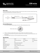
Standard cable Special cable
(electrode/coil) (electrode)
Basic data No. of conductors 3 3
Sqr. area 1.5 mm20.25 mm2
Screen Yes Double
Color code Brown, blue, black Brown, blue, black
Outside color Grey Grey
Ext. diameter 7.8 mm 8.1 mm
Conductor Flexible CU Flexible CU
Isolation material PVC PVC
Amb. temperature •Flexible installation −5 to 70°C−5 to 70°C
•Non flexible installation −30 to 70°C−30 to 70°C
Cable parameter Capacity 161.50 pF/m N.A.
Inductance 0.583 µH/m N.A.
L/R 43.83 µH/ΩN.A.
Special cable

19
SITRANS F M MAGFLO®3. Project guidance
SFIDK.PS.027.W4.02
Project guidance
3. Project guidance
3.1
Sizing table
(DN 2 to DN 2000)
The table shows the relationship between flow velocity V, flow quantity Q and sensor dimension
DN.
Guidelines for selection of sensor
Min. measuring range: 0-0.25 m/s
Max. measuring range: 0-10 m/s
Normally the sensor is selected so that V lies within the measuring range 1-2 m/s.
Flow velocity calculation formula:
V = 1273.24 x Q [l/s] [m/s]
DN2 [mm] or V = [m/s]
DN2 [mm]
353.68 x Q [m3/h]

20
SITRANS F M MAGFLO®3. Project guidance
SFIDK.PS.027.W4.02
Project guidance
3.2.1
Minimum conductivity Applications Min. conductivity
Compact/remote DN 2 & 3 30 µS/cm
DN ≥ 65 µS/cm
With empty pipe detection 20 µS/cm
Ex-installations
(Remote mounted only)
30 µS/cm
District heating systems
(Without DC cleaning unit)
250 µS/cm
3.2.2
Liner selection guide Liner Applications
Zirconium oxide ZrO2General purpose, agressive chemicals
Ceramics Al2O3General purpose, agressive chemicals
PFA General purpose, dairy, food and beverage
Neoprene General purpose, sewage
EPDM Drinking water, sea water
PTFE Agressive chemicals, paper and pulp, high temperature applica-
tions
Linatex®®
®®
®Abrasive media and mining slurries
Ebonite Drinking water
3.2.3
Electrode selection guide Electrodes Applications
AISI 316 Ti General purpose, water, sewage and district heating
AISI 316 Ti Ceramic coated High content of fibres, paper pulp
Hastelloy C-276 Good chemical proporties, sea water
Titanium Chlorine, chlorite, nitric and chromic acids
Textile bleaching industry
Tantalum Almost any acid solution
Platinum and platinum/irridium The ultimate electrode material. Unaffected by most liquids
3.3
Installation conditions
Reading and operating the flowmeter is possi-
ble under almost any installation conditions
because the display can be oriented in relation to
the sensor. To ensure optimum flow mea-
surement, attention should be paid to the fol-
lowing:
/