
40601200T90Z001K000
V5.00/EN/00643278
JUMO flowTRANS MAG S/H
Electromagnetic flowmeter
for the process industry and hygienic applications
for device versions 406012 - 406019
PED
Pressure
Equipment
Directive
Operating Manual


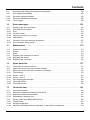
Contents
Contents
1 Safety . . . . . . . . . . . . . . . . . . . . . . . . . . . . . . . . . . . . . . . . . . . . . . . . . . . . . . . . . 9
1.1 General information and notes for the reader . . . . . . . . . . . . . . . . . . . . . . . . . . . . . . . . . . . . . . . 9
1.2 Other applicable device documentation . . . . . . . . . . . . . . . . . . . . . . . . . . . . . . . . . . . . . . . . . . . 9
1.3 Intended use . . . . . . . . . . . . . . . . . . . . . . . . . . . . . . . . . . . . . . . . . . . . . . . . . . . . . . . . . . . . . . . 10
1.4 Improper use. . . . . . . . . . . . . . . . . . . . . . . . . . . . . . . . . . . . . . . . . . . . . . . . . . . . . . . . . . . . . . . 10
1.5 Target groups and qualifications . . . . . . . . . . . . . . . . . . . . . . . . . . . . . . . . . . . . . . . . . . . . . . . . 10
1.6 Warranty conditions . . . . . . . . . . . . . . . . . . . . . . . . . . . . . . . . . . . . . . . . . . . . . . . . . . . . . . . . . 10
1.7 Symbols and signal words . . . . . . . . . . . . . . . . . . . . . . . . . . . . . . . . . . . . . . . . . . . . . . . . . . . . 11
1.7.1 Nameplate. . . . . . . . . . . . . . . . . . . . . . . . . . . . . . . . . . . . . . . . . . . . . . . . . . . . . . . . . . . . . . . . . 12
1.8 Transport safety information . . . . . . . . . . . . . . . . . . . . . . . . . . . . . . . . . . . . . . . . . . . . . . . . . . . 17
1.9 Safety information for mounting . . . . . . . . . . . . . . . . . . . . . . . . . . . . . . . . . . . . . . . . . . . . . . . . 17
1.10 Safety information for the electrical installation. . . . . . . . . . . . . . . . . . . . . . . . . . . . . . . . . . . . . 18
1.11 Safety information for operation . . . . . . . . . . . . . . . . . . . . . . . . . . . . . . . . . . . . . . . . . . . . . . . . 18
1.12 Technical limit values . . . . . . . . . . . . . . . . . . . . . . . . . . . . . . . . . . . . . . . . . . . . . . . . . . . . . . . . 19
1.13 Admissible measurement media. . . . . . . . . . . . . . . . . . . . . . . . . . . . . . . . . . . . . . . . . . . . . . . . 19
1.14 Safety information for inspections and maintenance . . . . . . . . . . . . . . . . . . . . . . . . . . . . . . . . 20
1.15 Returning devices . . . . . . . . . . . . . . . . . . . . . . . . . . . . . . . . . . . . . . . . . . . . . . . . . . . . . . . . . . . 20
1.16 Integrated management system . . . . . . . . . . . . . . . . . . . . . . . . . . . . . . . . . . . . . . . . . . . . . . . . 21
1.17 Disposal . . . . . . . . . . . . . . . . . . . . . . . . . . . . . . . . . . . . . . . . . . . . . . . . . . . . . . . . . . . . . . . . . . 21
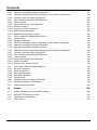
2 Design and function . . . . . . . . . . . . . . . . . . . . . . . . . . . . . . . . . . . . . . . . . . . . 23
2.1 Measuring principle. . . . . . . . . . . . . . . . . . . . . . . . . . . . . . . . . . . . . . . . . . . . . . . . . . . . . . . . . . 23
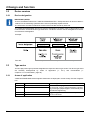
2.2 Device versions. . . . . . . . . . . . . . . . . . . . . . . . . . . . . . . . . . . . . . . . . . . . . . . . . . . . . . . . . . . . . 24
2.2.1 Device designation . . . . . . . . . . . . . . . . . . . . . . . . . . . . . . . . . . . . . . . . . . . . . . . . . . . . . . . . . . 24
2.3 Type series . . . . . . . . . . . . . . . . . . . . . . . . . . . . . . . . . . . . . . . . . . . . . . . . . . . . . . . . . . . . . . . . 24
2.3.1 Areas of application . . . . . . . . . . . . . . . . . . . . . . . . . . . . . . . . . . . . . . . . . . . . . . . . . . . . . . . . . 24
2.3.2 Functionalities . . . . . . . . . . . . . . . . . . . . . . . . . . . . . . . . . . . . . . . . . . . . . . . . . . . . . . . . . . . . . . 25
2.4 Design. . . . . . . . . . . . . . . . . . . . . . . . . . . . . . . . . . . . . . . . . . . . . . . . . . . . . . . . . . . . . . . . . . . . 26
2.4.1 Compact design type . . . . . . . . . . . . . . . . . . . . . . . . . . . . . . . . . . . . . . . . . . . . . . . . . . . . . . . . 26
2.4.2 Remote mount design type . . . . . . . . . . . . . . . . . . . . . . . . . . . . . . . . . . . . . . . . . . . . . . . . . . . . 26
2.4.3 Housing design type . . . . . . . . . . . . . . . . . . . . . . . . . . . . . . . . . . . . . . . . . . . . . . . . . . . . . . . . . 27
2.5 Explosion protection . . . . . . . . . . . . . . . . . . . . . . . . . . . . . . . . . . . . . . . . . . . . . . . . . . . . . . . . . 27
2.6 Overview of device versions . . . . . . . . . . . . . . . . . . . . . . . . . . . . . . . . . . . . . . . . . . . . . . . . . . . 28
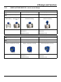
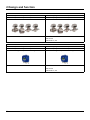
2.6.1 JUMO flowTRANS MAG S/H - compact design . . . . . . . . . . . . . . . . . . . . . . . . . . . . . . . . . . . . 28
2.6.2 JUMO flowTRANS MAG S/H - remote mount design . . . . . . . . . . . . . . . . . . . . . . . . . . . . . . . . 29
3 Transport and storage . . . . . . . . . . . . . . . . . . . . . . . . . . . . . . . . . . . . . . . . . . 31
3.1 Checking the delivery . . . . . . . . . . . . . . . . . . . . . . . . . . . . . . . . . . . . . . . . . . . . . . . . . . . . . . . . 31
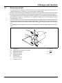
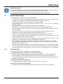
3.2 Transporting flanged devices . . . . . . . . . . . . . . . . . . . . . . . . . . . . . . . . . . . . . . . . . . . . . . . . . . 31
3.2.1 Flange devices up to DN 400 . . . . . . . . . . . . . . . . . . . . . . . . . . . . . . . . . . . . . . . . . . . . . . . . . . 31
3.2.2 Flange devices greater than DN 400 . . . . . . . . . . . . . . . . . . . . . . . . . . . . . . . . . . . . . . . . . . . . 32
3.3 Storage . . . . . . . . . . . . . . . . . . . . . . . . . . . . . . . . . . . . . . . . . . . . . . . . . . . . . . . . . . . . . . . . . . . 32
3.3.1 Nominal widths greater than DN 400 . . . . . . . . . . . . . . . . . . . . . . . . . . . . . . . . . . . . . . . . . . . . 32

Contents
4 Mounting . . . . . . . . . . . . . . . . . . . . . . . . . . . . . . . . . . . . . . . . . . . . . . . . . . . . . 33
4.1 General information . . . . . . . . . . . . . . . . . . . . . . . . . . . . . . . . . . . . . . . . . . . . . . . . . . . . . . . . . 33
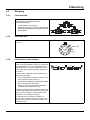
4.1.1 Selecting seals . . . . . . . . . . . . . . . . . . . . . . . . . . . . . . . . . . . . . . . . . . . . . . . . . . . . . . . . . . . . . 33
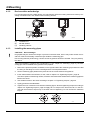
4.1.2 Devices with a wafer design . . . . . . . . . . . . . . . . . . . . . . . . . . . . . . . . . . . . . . . . . . . . . . . . . . . 34
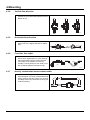
4.1.3 Installing the measuring pipes . . . . . . . . . . . . . . . . . . . . . . . . . . . . . . . . . . . . . . . . . . . . . . . . . 34
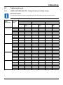
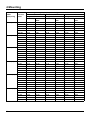
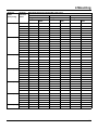
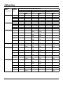
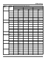
4.2 Tightening torques . . . . . . . . . . . . . . . . . . . . . . . . . . . . . . . . . . . . . . . . . . . . . . . . . . . . . . . . . . 35
4.2.1 JUMO flowTRANS MAG S/H - Flanged/connection flange design . . . . . . . . . . . . . . . . . . . . . . 35
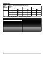
4.2.2 JUMO flowTRANS MAG H - Variable process connections . . . . . . . . . . . . . . . . . . . . . . . . . . . 40
4.3 Mounting . . . . . . . . . . . . . . . . . . . . . . . . . . . . . . . . . . . . . . . . . . . . . . . . . . . . . . . . . . . . . . . . . . 41
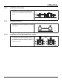
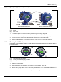
4.3.1 Flow direction . . . . . . . . . . . . . . . . . . . . . . . . . . . . . . . . . . . . . . . . . . . . . . . . . . . . . . . . . . . . . . 41
4.3.2 Electrode axis . . . . . . . . . . . . . . . . . . . . . . . . . . . . . . . . . . . . . . . . . . . . . . . . . . . . . . . . . . . . . . 41
4.3.3 Inlet section, outlet section . . . . . . . . . . . . . . . . . . . . . . . . . . . . . . . . . . . . . . . . . . . . . . . . . . . . 41
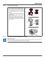
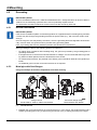
4.3.4 Vertical flow direction . . . . . . . . . . . . . . . . . . . . . . . . . . . . . . . . . . . . . . . . . . . . . . . . . . . . . . . . 42
4.3.5 Horizontal flow direction . . . . . . . . . . . . . . . . . . . . . . . . . . . . . . . . . . . . . . . . . . . . . . . . . . . . . . 42
4.3.6 Free inlet, free outlet . . . . . . . . . . . . . . . . . . . . . . . . . . . . . . . . . . . . . . . . . . . . . . . . . . . . . . . . . 42
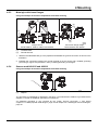
4.3.7 Heavily contaminated measurement media . . . . . . . . . . . . . . . . . . . . . . . . . . . . . . . . . . . . . . . 42
4.3.8 Installation near pumps. . . . . . . . . . . . . . . . . . . . . . . . . . . . . . . . . . . . . . . . . . . . . . . . . . . . . . . 43
4.3.9 Minimum clearance. . . . . . . . . . . . . . . . . . . . . . . . . . . . . . . . . . . . . . . . . . . . . . . . . . . . . . . . . . 43
4.3.10 Installation of the high-temperature version . . . . . . . . . . . . . . . . . . . . . . . . . . . . . . . . . . . . . . . 43
4.3.11 Installation in pipelines with larger nominal widths . . . . . . . . . . . . . . . . . . . . . . . . . . . . . . . . . . 44
4.3.12 3A-compliant mounting . . . . . . . . . . . . . . . . . . . . . . . . . . . . . . . . . . . . . . . . . . . . . . . . . . . . . . . 45
4.3.13 Devices with advanced diagnostics functions. . . . . . . . . . . . . . . . . . . . . . . . . . . . . . . . . . . . . . 45
4.4 Notes on opening and closing the housing . . . . . . . . . . . . . . . . . . . . . . . . . . . . . . . . . . . . . . . . 46
4.4.1 Rotation of the transmitter housing . . . . . . . . . . . . . . . . . . . . . . . . . . . . . . . . . . . . . . . . . . . . . . 47
4.4.2 Turning the LCD display . . . . . . . . . . . . . . . . . . . . . . . . . . . . . . . . . . . . . . . . . . . . . . . . . . . . . . 47
4.5 Grounding . . . . . . . . . . . . . . . . . . . . . . . . . . . . . . . . . . . . . . . . . . . . . . . . . . . . . . . . . . . . . . . . . 48
4.5.1 General information . . . . . . . . . . . . . . . . . . . . . . . . . . . . . . . . . . . . . . . . . . . . . . . . . . . . . . . . . 48
4.5.2 Metal pipe with fixed flanges. . . . . . . . . . . . . . . . . . . . . . . . . . . . . . . . . . . . . . . . . . . . . . . . . . . 48
4.5.3 Metal pipe with loose flanges . . . . . . . . . . . . . . . . . . . . . . . . . . . . . . . . . . . . . . . . . . . . . . . . . . 49
4.5.4 Sensor model 406015 and 406016. . . . . . . . . . . . . . . . . . . . . . . . . . . . . . . . . . . . . . . . . . . . . . 49
4.5.5 Plastic tubes, non-metallic tubes or tubes with insulating lining . . . . . . . . . . . . . . . . . . . . . . . . 50
4.5.6 Grounding devices with protection washers . . . . . . . . . . . . . . . . . . . . . . . . . . . . . . . . . . . . . . . 50
4.5.7 Grounding with conductive PTFE grounding washer . . . . . . . . . . . . . . . . . . . . . . . . . . . . . . . . 50
4.5.8 Devices with advanced diagnostics functions. . . . . . . . . . . . . . . . . . . . . . . . . . . . . . . . . . . . . . 50
4.5.9 Installation and grounding in pipelines with cathodic corrosion protection (CCP). . . . . . . . . . . 51
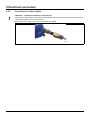
5 Electrical connection . . . . . . . . . . . . . . . . . . . . . . . . . . . . . . . . . . . . . . . . . . . 53
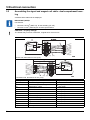
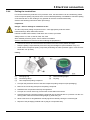
5.1 Installing the signal and magnet coil cable . . . . . . . . . . . . . . . . . . . . . . . . . . . . . . . . . . . . . . . . 53
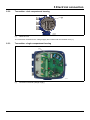
5.2 Assembling the signal and magnet coil cable - dual-compartment housing . . . . . . . . . . . . . . . 54
5.3 Assembling the signal and magnet coil cable - single-compartment housing. . . . . . . . . . . . . . 55
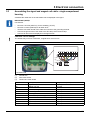
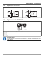
5.4 Sensor connection . . . . . . . . . . . . . . . . . . . . . . . . . . . . . . . . . . . . . . . . . . . . . . . . . . . . . . . . . . 56
5.4.1 Metal terminal boxes. . . . . . . . . . . . . . . . . . . . . . . . . . . . . . . . . . . . . . . . . . . . . . . . . . . . . . . . . 56
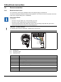
5.4.2 Protection type IP68 . . . . . . . . . . . . . . . . . . . . . . . . . . . . . . . . . . . . . . . . . . . . . . . . . . . . . . . . . 57

Contents
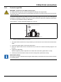
5.4.3 Connection via cable conduits . . . . . . . . . . . . . . . . . . . . . . . . . . . . . . . . . . . . . . . . . . . . . . . . . 58
5.4.4 Potting the terminal box . . . . . . . . . . . . . . . . . . . . . . . . . . . . . . . . . . . . . . . . . . . . . . . . . . . . . . 59
5.5 Transmitter connection . . . . . . . . . . . . . . . . . . . . . . . . . . . . . . . . . . . . . . . . . . . . . . . . . . . . . . . 60
5.5.1 Voltage supply connection . . . . . . . . . . . . . . . . . . . . . . . . . . . . . . . . . . . . . . . . . . . . . . . . . . . . 60
5.5.2 Transmitter - dual-compartment housing . . . . . . . . . . . . . . . . . . . . . . . . . . . . . . . . . . . . . . . . . 61
5.5.3 Transmitter - single-compartment housing . . . . . . . . . . . . . . . . . . . . . . . . . . . . . . . . . . . . . . . . 61
5.5.4 Signal and magnet coil cable connection . . . . . . . . . . . . . . . . . . . . . . . . . . . . . . . . . . . . . . . . . 62
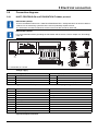
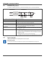
5.6 Connection diagrams . . . . . . . . . . . . . . . . . . . . . . . . . . . . . . . . . . . . . . . . . . . . . . . . . . . . . . . . 63
5.6.1 HART, PROFIBUS-PA and FOUNDATION Fieldbus protocol. . . . . . . . . . . . . . . . . . . . . . . . . . 63
5.7 Electrical data . . . . . . . . . . . . . . . . . . . . . . . . . . . . . . . . . . . . . . . . . . . . . . . . . . . . . . . . . . . . . . 64
5.7.1 Current/HART output . . . . . . . . . . . . . . . . . . . . . . . . . . . . . . . . . . . . . . . . . . . . . . . . . . . . . . . . 64
5.7.2 Digital output DO1. . . . . . . . . . . . . . . . . . . . . . . . . . . . . . . . . . . . . . . . . . . . . . . . . . . . . . . . . . . 65
5.7.3 Digital output DO2. . . . . . . . . . . . . . . . . . . . . . . . . . . . . . . . . . . . . . . . . . . . . . . . . . . . . . . . . . . 65
5.7.4 Digital input DI1. . . . . . . . . . . . . . . . . . . . . . . . . . . . . . . . . . . . . . . . . . . . . . . . . . . . . . . . . . . . . 66
5.7.5 PROFIBUS-PA (PA+/PA-) / FOUNDATION Fieldbus (FF+/FF-) - according to IEC 61158-2 . . 66
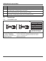
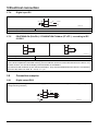
5.8 Connection examples . . . . . . . . . . . . . . . . . . . . . . . . . . . . . . . . . . . . . . . . . . . . . . . . . . . . . . . . 66
5.8.1 Digital output DO2. . . . . . . . . . . . . . . . . . . . . . . . . . . . . . . . . . . . . . . . . . . . . . . . . . . . . . . . . . . 66
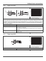
5.8.2 Digital outputs DO1 and DO2 . . . . . . . . . . . . . . . . . . . . . . . . . . . . . . . . . . . . . . . . . . . . . . . . . . 67
5.8.3 Digital communication PROFIBUS-PA . . . . . . . . . . . . . . . . . . . . . . . . . . . . . . . . . . . . . . . . . . . 67
6 Digital communication . . . . . . . . . . . . . . . . . . . . . . . . . . . . . . . . . . . . . . . . . . 69
6.1 HART protocol . . . . . . . . . . . . . . . . . . . . . . . . . . . . . . . . . . . . . . . . . . . . . . . . . . . . . . . . . . . . . 69
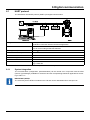
6.1.1 System integration . . . . . . . . . . . . . . . . . . . . . . . . . . . . . . . . . . . . . . . . . . . . . . . . . . . . . . . . . . 69
6.2 PROFIBUS-PA protocol . . . . . . . . . . . . . . . . . . . . . . . . . . . . . . . . . . . . . . . . . . . . . . . . . . . . . . 70
6.2.1 System integration . . . . . . . . . . . . . . . . . . . . . . . . . . . . . . . . . . . . . . . . . . . . . . . . . . . . . . . . . . 70
6.3 FOUNDATION Fieldbus (FF) . . . . . . . . . . . . . . . . . . . . . . . . . . . . . . . . . . . . . . . . . . . . . . . . . . 71
6.3.1 System integration . . . . . . . . . . . . . . . . . . . . . . . . . . . . . . . . . . . . . . . . . . . . . . . . . . . . . . . . . . 71
7 Startup . . . . . . . . . . . . . . . . . . . . . . . . . . . . . . . . . . . . . . . . . . . . . . . . . . . . . . . 73
7.1 Checks prior to start-up. . . . . . . . . . . . . . . . . . . . . . . . . . . . . . . . . . . . . . . . . . . . . . . . . . . . . . . 73
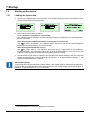
7.2 Configuring the current output . . . . . . . . . . . . . . . . . . . . . . . . . . . . . . . . . . . . . . . . . . . . . . . . . 73
7.2.1 Transmitter - dual-compartment housing . . . . . . . . . . . . . . . . . . . . . . . . . . . . . . . . . . . . . . . . . 74
7.2.2 Transmitter - single-compartment housing . . . . . . . . . . . . . . . . . . . . . . . . . . . . . . . . . . . . . . . . 75
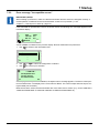
7.3 Startup of PROFIBUS-PA devices . . . . . . . . . . . . . . . . . . . . . . . . . . . . . . . . . . . . . . . . . . . . . . 76
7.3.1 Setting the address locally for transmitters with a dual-compartment housing . . . . . . . . . . . . . 77
7.3.2 Configuration for transmitters with a single-compartment housing . . . . . . . . . . . . . . . . . . . . . . 78
7.3.3 Voltage/current consumption . . . . . . . . . . . . . . . . . . . . . . . . . . . . . . . . . . . . . . . . . . . . . . . . . . 79
7.3.4 System integration . . . . . . . . . . . . . . . . . . . . . . . . . . . . . . . . . . . . . . . . . . . . . . . . . . . . . . . . . . 79
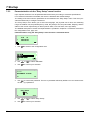
7.4 Startup for FOUNDATION Fieldbus devices . . . . . . . . . . . . . . . . . . . . . . . . . . . . . . . . . . . . . . . 80
7.4.1 Configuration for transmitters with a dual-compartment housing . . . . . . . . . . . . . . . . . . . . . . . 81
7.4.2 Configuration for transmitters with a single-compartment housing . . . . . . . . . . . . . . . . . . . . . . 82
7.4.3 Setting the bus address . . . . . . . . . . . . . . . . . . . . . . . . . . . . . . . . . . . . . . . . . . . . . . . . . . . . . . 83

Contents
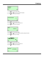
7.5 Starting up the device . . . . . . . . . . . . . . . . . . . . . . . . . . . . . . . . . . . . . . . . . . . . . . . . . . . . . . . . 84
7.5.1 Loading the system data. . . . . . . . . . . . . . . . . . . . . . . . . . . . . . . . . . . . . . . . . . . . . . . . . . . . . . 84
7.5.2 Error message "Incompatible sensor". . . . . . . . . . . . . . . . . . . . . . . . . . . . . . . . . . . . . . . . . . . . 85
7.5.3 Parameterization via the "Easy Setup" menu function . . . . . . . . . . . . . . . . . . . . . . . . . . . . . . . 86
7.6 Nominal width, measuring range . . . . . . . . . . . . . . . . . . . . . . . . . . . . . . . . . . . . . . . . . . . . . . . 92
8 Parameterization . . . . . . . . . . . . . . . . . . . . . . . . . . . . . . . . . . . . . . . . . . . . . . . 95
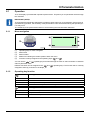
8.1 Operation . . . . . . . . . . . . . . . . . . . . . . . . . . . . . . . . . . . . . . . . . . . . . . . . . . . . . . . . . . . . . . . . . 95
8.1.1 Menu navigation . . . . . . . . . . . . . . . . . . . . . . . . . . . . . . . . . . . . . . . . . . . . . . . . . . . . . . . . . . . . 95
8.1.2 Operating key function . . . . . . . . . . . . . . . . . . . . . . . . . . . . . . . . . . . . . . . . . . . . . . . . . . . . . . . 95
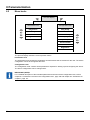
8.2 Menu levels. . . . . . . . . . . . . . . . . . . . . . . . . . . . . . . . . . . . . . . . . . . . . . . . . . . . . . . . . . . . . . . . 96
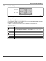
8.2.1 Process display. . . . . . . . . . . . . . . . . . . . . . . . . . . . . . . . . . . . . . . . . . . . . . . . . . . . . . . . . . . . . 97
8.2.2 Switch to the Information level (Operator Menu) . . . . . . . . . . . . . . . . . . . . . . . . . . . . . . . . . . . 98
8.2.3 Switching to the Configuration level (Parameterization) . . . . . . . . . . . . . . . . . . . . . . . . . . . . . 101
8.2.4 Hardware write protection . . . . . . . . . . . . . . . . . . . . . . . . . . . . . . . . . . . . . . . . . . . . . . . . . . . . 102
8.2.5 Selecting and changing parameters . . . . . . . . . . . . . . . . . . . . . . . . . . . . . . . . . . . . . . . . . . . . 103
8.3 Parameter overview in the configuration level . . . . . . . . . . . . . . . . . . . . . . . . . . . . . . . . . . . . 105
8.4 Parameter description. . . . . . . . . . . . . . . . . . . . . . . . . . . . . . . . . . . . . . . . . . . . . . . . . . . . . . . 113
8.4.1 Menu: Easy Setup. . . . . . . . . . . . . . . . . . . . . . . . . . . . . . . . . . . . . . . . . . . . . . . . . . . . . . . . . . 113
8.4.2 Menu: Device info . . . . . . . . . . . . . . . . . . . . . . . . . . . . . . . . . . . . . . . . . . . . . . . . . . . . . . . . . . 115
8.4.3 Menu: Device Setup . . . . . . . . . . . . . . . . . . . . . . . . . . . . . . . . . . . . . . . . . . . . . . . . . . . . . . . . 119
8.4.4 Menu: Display . . . . . . . . . . . . . . . . . . . . . . . . . . . . . . . . . . . . . . . . . . . . . . . . . . . . . . . . . . . . . 123
8.4.5 Menu: Input/Output . . . . . . . . . . . . . . . . . . . . . . . . . . . . . . . . . . . . . . . . . . . . . . . . . . . . . . . . . 125
8.4.6 Menu: Process alarm . . . . . . . . . . . . . . . . . . . . . . . . . . . . . . . . . . . . . . . . . . . . . . . . . . . . . . . 130
8.4.7 Menu: Communication . . . . . . . . . . . . . . . . . . . . . . . . . . . . . . . . . . . . . . . . . . . . . . . . . . . . . . 131
8.4.8 Menu: Diagnostics . . . . . . . . . . . . . . . . . . . . . . . . . . . . . . . . . . . . . . . . . . . . . . . . . . . . . . . . . 136
8.4.9 Menu: Totalizer . . . . . . . . . . . . . . . . . . . . . . . . . . . . . . . . . . . . . . . . . . . . . . . . . . . . . . . . . . . . 145
8.5 Alarm Simulation. . . . . . . . . . . . . . . . . . . . . . . . . . . . . . . . . . . . . . . . . . . . . . . . . . . . . . . . . . . 147
8.6 Filling operation - JUMO flowTRANS MAG S02/H02 . . . . . . . . . . . . . . . . . . . . . . . . . . . . . . . 149
8.6.1 Configuration. . . . . . . . . . . . . . . . . . . . . . . . . . . . . . . . . . . . . . . . . . . . . . . . . . . . . . . . . . . . . . 150
9 Advanced diagnostics functions . . . . . . . . . . . . . . . . . . . . . . . . . . . . . . . . . 153
9.1 General Information . . . . . . . . . . . . . . . . . . . . . . . . . . . . . . . . . . . . . . . . . . . . . . . . . . . . . . . . 153
9.1.1 Partial filling detection . . . . . . . . . . . . . . . . . . . . . . . . . . . . . . . . . . . . . . . . . . . . . . . . . . . . . . . 153
9.1.2 Gas bubble detection . . . . . . . . . . . . . . . . . . . . . . . . . . . . . . . . . . . . . . . . . . . . . . . . . . . . . . . 153
9.1.3 Electrode coating detection. . . . . . . . . . . . . . . . . . . . . . . . . . . . . . . . . . . . . . . . . . . . . . . . . . . 154
9.1.4 Conductivity monitoring. . . . . . . . . . . . . . . . . . . . . . . . . . . . . . . . . . . . . . . . . . . . . . . . . . . . . . 154
9.1.5 Electrode impedance monitoring . . . . . . . . . . . . . . . . . . . . . . . . . . . . . . . . . . . . . . . . . . . . . . 155
9.1.6 Sensor measurements . . . . . . . . . . . . . . . . . . . . . . . . . . . . . . . . . . . . . . . . . . . . . . . . . . . . . . 155
9.1.7 Trend. . . . . . . . . . . . . . . . . . . . . . . . . . . . . . . . . . . . . . . . . . . . . . . . . . . . . . . . . . . . . . . . . . . . 155
9.1.8 Fingerprint. . . . . . . . . . . . . . . . . . . . . . . . . . . . . . . . . . . . . . . . . . . . . . . . . . . . . . . . . . . . . . . . 156
9.1.9 Checking the grounding . . . . . . . . . . . . . . . . . . . . . . . . . . . . . . . . . . . . . . . . . . . . . . . . . . . . . 156
9.2 Conducting the grounding check . . . . . . . . . . . . . . . . . . . . . . . . . . . . . . . . . . . . . . . . . . . . . . 156

Contents
9.3 Recommended settings for diagnostics thresholds . . . . . . . . . . . . . . . . . . . . . . . . . . . . . . . . 158
9.3.1 Coil resistance thresholds. . . . . . . . . . . . . . . . . . . . . . . . . . . . . . . . . . . . . . . . . . . . . . . . . . . . 158
9.3.2 Electrode coating thresholds. . . . . . . . . . . . . . . . . . . . . . . . . . . . . . . . . . . . . . . . . . . . . . . . . . 159
9.3.3 Electrode impedance thresholds. . . . . . . . . . . . . . . . . . . . . . . . . . . . . . . . . . . . . . . . . . . . . .. 159
9.3.4 Trend Logger. . . . . . . . . . . . . . . . . . . . . . . . . . . . . . . . . . . . . . . . . . . . . . . . . . . . . . . . . . . . . . 159
10 Error messages . . . . . . . . . . . . . . . . . . . . . . . . . . . . . . . . . . . . . . . . . . . . . . . 161
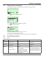
10.1 Calling up the error description . . . . . . . . . . . . . . . . . . . . . . . . . . . . . . . . . . . . . . . . . . . . . . . . 161
10.2 Error statuses and alarms. . . . . . . . . . . . . . . . . . . . . . . . . . . . . . . . . . . . . . . . . . . . . . . . . . . . 161
10.2.1 Error . . . . . . . . . . . . . . . . . . . . . . . . . . . . . . . . . . . . . . . . . . . . . . . . . . . . . . . . . . . . . . . . . . . . 161
10.2.2 Function Check . . . . . . . . . . . . . . . . . . . . . . . . . . . . . . . . . . . . . . . . . . . . . . . . . . . . . . . . . . . . 162
10.2.3 Operating the device out of spec . . . . . . . . . . . . . . . . . . . . . . . . . . . . . . . . . . . . . . . . . . . . .. 165
10.2.4 Maintenance . . . . . . . . . . . . . . . . . . . . . . . . . . . . . . . . . . . . . . . . . . . . . . . . . . . . . . . . . . . . . . 167
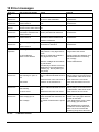
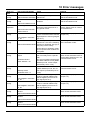
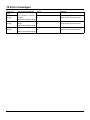
10.3 Overview of the error statuses and alarms . . . . . . . . . . . . . . . . . . . . . . . . . . . . . . . . . . . . . . . 167
10.3.1 Error message during startup . . . . . . . . . . . . . . . . . . . . . . . . . . . . . . . . . . . . . . . . . . . . . . . . . 171
11 Maintenance. . . . . . . . . . . . . . . . . . . . . . . . . . . . . . . . . . . . . . . . . . . . . . . . . . 173
11.1 General information . . . . . . . . . . . . . . . . . . . . . . . . . . . . . . . . . . . . . . . . . . . . . . . . . . . . . . . . 173
11.2 Sensor. . . . . . . . . . . . . . . . . . . . . . . . . . . . . . . . . . . . . . . . . . . . . . . . . . . . . . . . . . . . . . . . . . . 174
11.3 Seals . . . . . . . . . . . . . . . . . . . . . . . . . . . . . . . . . . . . . . . . . . . . . . . . . . . . . . . . . . . . . . . . . . . . 174
11.4 Replacing the transmitter or sensor . . . . . . . . . . . . . . . . . . . . . . . . . . . . . . . . . . . . . . . . . . . . 175
11.4.1 Replacing the sensor . . . . . . . . . . . . . . . . . . . . . . . . . . . . . . . . . . . . . . . . . . . . . . . . . . . . . . . 175
11.4.2 Replacing the transmitter . . . . . . . . . . . . . . . . . . . . . . . . . . . . . . . . . . . . . . . . . . . . . . . . . . . . 176
12 Spare parts list. . . . . . . . . . . . . . . . . . . . . . . . . . . . . . . . . . . . . . . . . . . . . . . . 177
12.1 Transmitter electronics unit fuse . . . . . . . . . . . . . . . . . . . . . . . . . . . . . . . . . . . . . . . . . . . . . .. 177
12.2 Spare parts for devices with a compact design. . . . . . . . . . . . . . . . . . . . . . . . . . . . . . . . . . . . 177
12.3 Spare parts for devices with a remote mount design . . . . . . . . . . . . . . . . . . . . . . . . . . . . . . . 178
12.3.1 Field housing. . . . . . . . . . . . . . . . . . . . . . . . . . . . . . . . . . . . . . . . . . . . . . . . . . . . . . . . . . . . . . 178
12.3.2 Sensor - zone 2. . . . . . . . . . . . . . . . . . . . . . . . . . . . . . . . . . . . . . . . . . . . . . . . . . . . . . . . . . . . 179
12.3.3 Sensor - zone 1. . . . . . . . . . . . . . . . . . . . . . . . . . . . . . . . . . . . . . . . . . . . . . . . . . . . . . . . . . . . 179
12.4 3A-compliant seal materials . . . . . . . . . . . . . . . . . . . . . . . . . . . . . . . . . . . . . . . . . . . . . . . . . . 180
12.4.1 Flat seals EPDM . . . . . . . . . . . . . . . . . . . . . . . . . . . . . . . . . . . . . . . . . . . . . . . . . . . . . . . . . . . 180
12.4.2 Flat seals silicone . . . . . . . . . . . . . . . . . . . . . . . . . . . . . . . . . . . . . . . . . . . . . . . . . . . . . . . . . . 180
13 Technical data . . . . . . . . . . . . . . . . . . . . . . . . . . . . . . . . . . . . . . . . . . . . . . . . 181
13.1 General information . . . . . . . . . . . . . . . . . . . . . . . . . . . . . . . . . . . . . . . . . . . . . . . . . . . . . . . . 181
13.1.1 Reference conditions according to EN 29104. . . . . . . . . . . . . . . . . . . . . . . . . . . . . . . . . . . . . 181
13.1.2 Maximum measurement deviation . . . . . . . . . . . . . . . . . . . . . . . . . . . . . . . . . . . . . . . . . . . . . 181
13.1.3 Repeatability, response time . . . . . . . . . . . . . . . . . . . . . . . . . . . . . . . . . . . . . . . . . . . . . . . . . . 182
13.2 Sensor JUMO flowTRANS MAG S01/02 . . . . . . . . . . . . . . . . . . . . . . . . . . . . . . . . . . . . . . . . 183
13.2.1 Temperatures . . . . . . . . . . . . . . . . . . . . . . . . . . . . . . . . . . . . . . . . . . . . . . . . . . . . . . . . . . . . . 183
13.2.2 Storage temperature . . . . . . . . . . . . . . . . . . . . . . . . . . . . . . . . . . . . . . . . . . . . . . . . . . . . . . . . 183
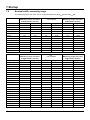
13.2.3 Minimum admissible pressure depending on the medium temperature . . . . . . . . . . . . . . . . . 183

Contents
13.2.4 Maximum admissible cleaning temperature . . . . . . . . . . . . . . . . . . . . . . . . . . . . . . . . . . . . . . 183
13.2.5 Maximum ambient temperature depending on the medium temperature . . . . . . . . . . . . . . . . 184
13.2.6 Protection type according to EN 60529 . . . . . . . . . . . . . . . . . . . . . . . . . . . . . . . . . . . . . . . . . 185
13.2.7 Pipe vibration according to EN 60068-2-6 . . . . . . . . . . . . . . . . . . . . . . . . . . . . . . . . . . . . . . . 185
13.2.8 Insertion length . . . . . . . . . . . . . . . . . . . . . . . . . . . . . . . . . . . . . . . . . . . . . . . . . . . . . . . . . . . . 186
13.2.9 Signal cable length and preamplifier. . . . . . . . . . . . . . . . . . . . . . . . . . . . . . . . . . . . . . . . . . . . 186
13.2.10 Sensor materials . . . . . . . . . . . . . . . . . . . . . . . . . . . . . . . . . . . . . . . . . . . . . . . . . . . . . . . . . . . 187
13.2.11 Process connection materials . . . . . . . . . . . . . . . . . . . . . . . . . . . . . . . . . . . . . . . . . . . . . . . . . 189
13.2.12 Measuring pipe materials . . . . . . . . . . . . . . . . . . . . . . . . . . . . . . . . . . . . . . . . . . . . . . . . . . . . 189
13.2.13 Material load on sensor housing . . . . . . . . . . . . . . . . . . . . . . . . . . . . . . . . . . . . . . . . . . . . . . . 189
13.3 Sensor JUMO flowTRANS MAG H01/02 . . . . . . . . . . . . . . . . . . . . . . . . . . . . . . . . . . . . . . . . 192
13.3.1 Temperatures . . . . . . . . . . . . . . . . . . . . . . . . . . . . . . . . . . . . . . . . . . . . . . . . . . . . . . . . . . . . . 192
13.3.2 Storage temperature . . . . . . . . . . . . . . . . . . . . . . . . . . . . . . . . . . . . . . . . . . . . . . . . . . . . . . . . 192
13.3.3 Minimum admissible pressure depending on the medium temperature . . . . . . . . . . . . . . . . . 192
13.3.4 Maximum admissible cleaning temperature . . . . . . . . . . . . . . . . . . . . . . . . . . . . . . . . . . . . . . 192
13.3.5 Maximum admissible temperature shock . . . . . . . . . . . . . . . . . . . . . . . . . . . . . . . . . . . . . . . . 192
13.3.6 Maximum ambient temperature depending on the medium temperature . . . . . . . . . . . . . . . . 193
13.3.7 Protection type according to EN 60529 . . . . . . . . . . . . . . . . . . . . . . . . . . . . . . . . . . . . . . . . . 193
13.3.8 Pipe vibration according to EN 60068-2-6 . . . . . . . . . . . . . . . . . . . . . . . . . . . . . . . . . . . . . . . 193
13.3.9 Insertion length . . . . . . . . . . . . . . . . . . . . . . . . . . . . . . . . . . . . . . . . . . . . . . . . . . . . . . . . . . . . 193
13.3.10 Signal cable length and preamplifier. . . . . . . . . . . . . . . . . . . . . . . . . . . . . . . . . . . . . . . . . . . . 194
13.3.11 Sensor materials . . . . . . . . . . . . . . . . . . . . . . . . . . . . . . . . . . . . . . . . . . . . . . . . . . . . . . . . . . . 195
13.3.12 Material load - sensor housing . . . . . . . . . . . . . . . . . . . . . . . . . . . . . . . . . . . . . . . . . . . . . . . . 196
13.4 Transmitter JUMO flowTRANS MAG 01 . . . . . . . . . . . . . . . . . . . . . . . . . . . . . . . . . . . . . . . . . 198
13.4.1 Electrical properties . . . . . . . . . . . . . . . . . . . . . . . . . . . . . . . . . . . . . . . . . . . . . . . . . . . . . . . . 198
13.4.2 Electrical isolation . . . . . . . . . . . . . . . . . . . . . . . . . . . . . . . . . . . . . . . . . . . . . . . . . . . . . . . . . . 198
13.4.3 Empty pipe detection . . . . . . . . . . . . . . . . . . . . . . . . . . . . . . . . . . . . . . . . . . . . . . . . . . . . . . . 198
13.4.4 Mechanical features . . . . . . . . . . . . . . . . . . . . . . . . . . . . . . . . . . . . . . . . . . . . . . . . . . . . . . . . 198
13.4.5 Temperatures . . . . . . . . . . . . . . . . . . . . . . . . . . . . . . . . . . . . . . . . . . . . . . . . . . . . . . . . . . . . . 198
13.4.6 Protection type according to EN 60529 . . . . . . . . . . . . . . . . . . . . . . . . . . . . . . . . . . . . . . . . . 198
13.4.7 Vibration according to EN 60068-2 . . . . . . . . . . . . . . . . . . . . . . . . . . . . . . . . . . . . . . . . . . . . . 199
13.5 Approvals/approval marks . . . . . . . . . . . . . . . . . . . . . . . . . . . . . . . . . . . . . . . . . . . . . . . . . . . 200
14 Annex . . . . . . . . . . . . . . . . . . . . . . . . . . . . . . . . . . . . . . . . . . . . . . . . . . . . . . . 209
14.1 Setting parameter overview (default setting) . . . . . . . . . . . . . . . . . . . . . . . . . . . . . . . . . . . . . 209
14.1.1 With the PROFIBUS-PA version . . . . . . . . . . . . . . . . . . . . . . . . . . . . . . . . . . . . . . . . . . . . . . . 210
14.2 Approvals and certifications . . . . . . . . . . . . . . . . . . . . . . . . . . . . . . . . . . . . . . . . . . . . . . . . . . 210
14.3 China RoHS . . . . . . . . . . . . . . . . . . . . . . . . . . . . . . . . . . . . . . . . . . . . . . . . . . . . . . . . . . . . . . 255

9
1 Safety
1Safety
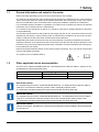
1.1 General information and notes for the reader
Before mounting and starting up the unit, this manual must be read carefully.
The manual is an integral part of the product and must be stored for subsequent use. In the interest of
clarity, the manual does not contain all the detailed information about all product versions and cannot
take into consideration every conceivable case involving the installation, operation or maintenance.
If you would like further information or if problems occur that are not covered by the manual, the required
information can be obtained from the manufacturer.
The contents of this manual are not part of or a change to a previous or existing agreement, assurance
or legal relationship.
This product is built based on state-of-the-art technology and safe to use. It has been tested and was
shipped from the factory in perfect working order. To maintain this condition for its service life, the infor-
mation contained in these instructions must be observed and followed.
Modifications and repairs to the product may only be performed if expressly permitted by this manual.
Optimum protection of the personnel and the environment and the safe and smooth operation of this
product are only ensured by observing all the safety information as well as all safety and warning sym-
bols contained in this manual.
Notes and symbols attached directly on the product must be observed. They may not be removed and
must be fully legible at all times.
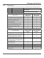
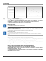
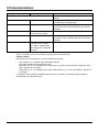
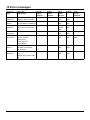
1.2 Other applicable device documentation
This document "JUMO flowTRANS MAG S/H - Operating Manual for Devices 406012 - 406019" is sup-
plemented by the documents listed below:
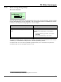
The symbol on the nameplate refers to:
?
?
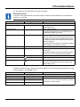
Document name Document type For devices
JUMO flowTRANS MAG S/H Ex Safety Manuala
aOptional - depending on the device version
406012 - 406019
JUMO flowTRANS MAG S/H SILa Safety Manual 406012 - 406019
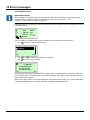
IMPORTANT (NOTE)!
The supplementary document "JUMO flowTRANS MAG S/H - Ex Safety Manual for Devices 406012 -
406019" is enclosed with measuring systems used in potentially explosive areas.
The information and data contained in the document must also be strictly observed.
IMPORTANT (NOTE)!
The supplementary document "JUMO flowTRANS MAG S/H - SIL Safety Manual for Devices 406012 -
406019" is enclosed with measuring systems with an SIL-certified design (safety integrity level).
The information and data contained in the document must also be strictly observed.
IMPORTANT (NOTE)!
All the documentation, declarations of conformity and certificates are also available in the download area
at www.jumo.de.

1 Safety
10
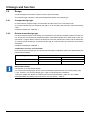
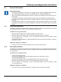
1.3 Intended use
This device serves the following purposes:
• To transfer liquid, pulpy or pasty measurement media with electrical conductivity
• To measure the flow of the operating volume or measurement units (with constant pressure/tempera-
ture) if a physical measuring unit has been selected
Intended use also includes the following points:
• Observing and following the instructions provided in this manual
• Technical limit values must be observed, see chapter 1.12 "Technical limit values", page 19
• approved measurement media must be observed, see chapter 1.13 "Admissible measurement
media", page 19
1.4 Improper use
The device may not be used for the following:
• Operation as an elastic compensating piece in pipelines, e.g. for compensating pipe offsets, pipe vi-
brations, pipe expansions,
• Use as a climbing aid, e.g. for mounting purposes
• Use as a holder for external loads, e.g. as a holder for pipelines
• Applying materials, e.g. by painting over the nameplate or welding or soldering parts
• Removing materials, e.g. by drilling the housing
1.5 Target groups and qualifications
The product may only be installed, started up and maintained by adequately trained qualified personnel
who have been authorized by the system operator. The qualified personnel must have read and under-
stood the manual and follow the instructions.
Before using corrosive and abrasive measurement media, the operator must check the degree of resis-
tance of all parts coming into contact with the media. The manufacturer is happy to provide support in
selecting the media, but cannot accept any liability.
The operator must observe the national regulations, which apply in the country where the product is
used, with regard to the installation, functional inspections, repairs and maintenance of electrical prod-
ucts.
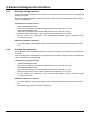
1.6 Warranty conditions
IMPORTANT (NOTE)!
Improper use, failure to observe this manual, the use of underqualified personnel, or unauthorized mod-
ifications releases the manufacturer from liability for any resulting damage. In these cases, the manufac-
turer's warranty no longer applies.

11
1 Safety
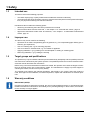
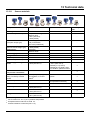
1.7 Symbols and signal words
DANGER – Serious damage to health/risk to life!
This symbol in connection with the signal word "Danger" indicates an imminent threat of danger. Failure
to observe the safety information results in death or serious injuries.
DANGER – Serious damage to health/risk to life!
This symbol in connection with the signal word "Danger" indicates an imminent threat of danger due to
electric current. Failure to observe the safety information results in death or serious injuries.
WARNING – Personal injuries!
This symbol in connection with the signal word "Warning" indicates a potentially dangerous situation.
Failure to observe the safety information may result in death or serious injuries.
WARNING – Personal injuries!
This symbol in connection with the signal word "Warning" indicates a potentially dangerous situation due
to electric current. Failure to observe the safety information may result in death or serious injuries.
CAUTION – Minor injuries!
This symbol in connection with the signal word "Caution" indicates a potentially dangerous situation. Fail-
ure to observe the safety information may result in minor or moderate injuries. It may also be used for
warnings against property damage.
CAUTION – Property damage!
This symbol indicates a potentially harmful situation. Failure to observe the safety information may dam-
age or destroy the device and/or other system parts.
IMPORTANT (NOTE)!
This symbol indicates user tips, particularly useful or important information about the device; or its addi-
tional uses. This is not a signal word for a dangerous or harmful situation.
IMPORTANT (NOTE)!
This symbol is used in tables and indicates that further information is provided after the table.
?
DISPOSAL!
At the end of its service life, the device and any batteries present do not belong in the trash! Please en-
sure that they are disposed of properly and in an environmentally friendly manner.

1 Safety
12
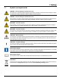
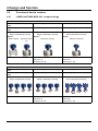
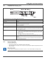
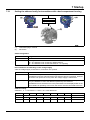
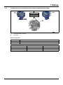
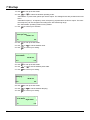
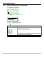
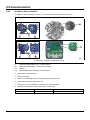
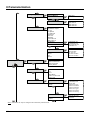
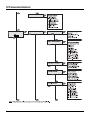
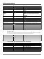
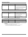
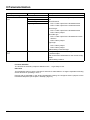
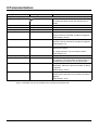
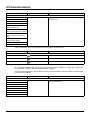
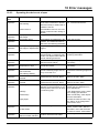
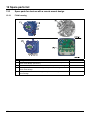
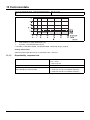
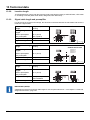
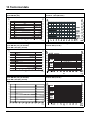
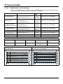
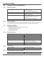
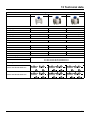
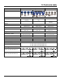
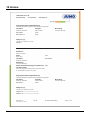
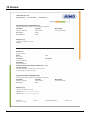
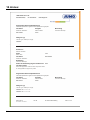
1.7.1 Nameplate
IMPORTANT (NOTE)!
There is the additional document "JUMO flowTRANS MAG S/H - Safety Manual Ex for devices 406012 -
406019" for the measuring systems that are used in potentially explosive areas.
The information and data contained in the document must also be strictly observed.

13
1 Safety
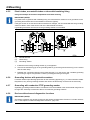
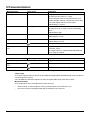
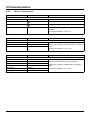
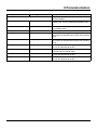
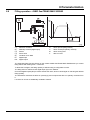
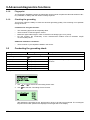
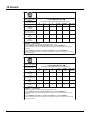
(1) Model number (for technical version details, see data sheet or order confirmation)
(2) Serial number for identification by the manufacturer
(3) Nominal width and nominal pressure levels
(4) Material: flange/lining/electrode
(5) Tmed = Maximum admissible measurement medium temperature
Tamb = Maximum admissible ambient temperature
(6) Calibration value Qmax DN
(7) Calibration value Ss (range)
Calibration value Sz (zero point)
(8) Transmitter communication protocol
(9) Excitation frequency of the sensor coils
(10) Software version
(11) Year of construction
(12) CE mark
(13) Order number
(14) Customer-specific TAG number (if provided)
(15) Protection type according to DIN EN 60529
(16) Additional information: EE = Grounding electrodes, TFE = Partial filling electrode
(17) Accuracy with which the device was calibrated (e.g. 0.2 % of the measured value)
(18) Revision status (xx.xx.xx)
(19) Identification marking indicating whether the pressure device falls within the scope of the Pressure Equipment
Directive.aSpecification of the fluid group taken into consideration.
Fluid group 1 = Dangerous fluids, liquid, gaseous (Pressure Equipment Directive = PED)
If the pressure device is outside the scope of the Pressure Equipment Directivea, the classification is carried
out in the SEP (Sound Engineering Practice) category according to Art. 3 Para. 3 of the PED.
If the details are completely missing, then conformity with the requirements of the Pressure Equipment Direc-
tivea is not given. The exception for water networks and connection equipment parts according to guideline 1/
16 to art. 1. para. 3.2 of the Pressure Equipment Directive applies.
(20) Ex identification marking according to ATEX (example)
(21) Ex identification marking according to IECEx (example)
aPressure Equipment Directive (PED) 2014/68/EU (Mod. B+D).
*
=RQH
=RQH
=RQH
=RQH

1 Safety
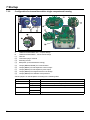
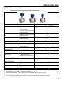
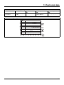
14
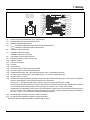
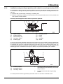
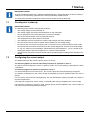
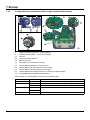
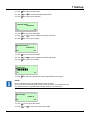
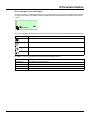
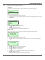
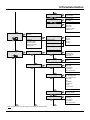
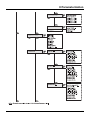
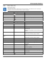
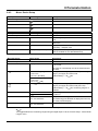
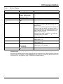
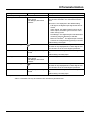
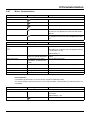
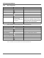
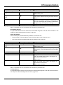
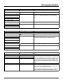
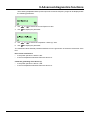
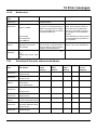
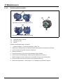
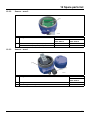
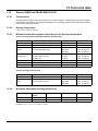
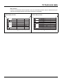
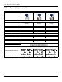
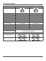
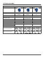
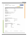
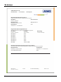
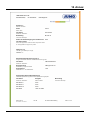
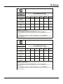
A Nameplate
(1) Model number (for technical version details, see data sheet or order confirmation)
(2) Serial number for identification by the manufacturer
(3) Nominal width and nominal pressure levels
(4) Tmed = Maximum admissible measurement medium temperature
Tamb = Maximum admissible ambient temperature
(5) Protection type according to DIN EN 60529
(6) Calibration value Qmax DN
(7) Transmitter communication protocol
(8) Software version
(9) CE mark
(10) Order number
(11) Customer-specific TAG number (if provided)
(12) Material: flange/lining/electrode
(13) Excitation frequency of the sensor coils
(14) Additional information: EE = Grounding electrodes, TFE = Partial filling electrode
Calibration value Ss (range)
Calibration value Sz (zero point)
(15) Accuracy with which the device was calibrated (e.g. 0.4 % of the measured value)
(16) Voltage supply
(17) Year of construction
(18) Identification marking indicating whether the pressure device falls within the scope of the Pressure Equipment
Directive.aSpecification of the fluid group taken into consideration.
Fluid group 1 = Dangerous fluids, liquid, gaseous (Pressure Equipment Directive = PED)
If the pressure device is outside the scope of the Pressure Equipment Directivea, the classification is carried
out in the SEP (Sound Engineering Practice) category according to Art. 3 Para. 3 of the PED.
If the details are completely missing, then conformity with the requirements of the Pressure Equipment Direc-
tivea is not given. The exception for water networks and connection equipment parts according to guideline 1/
16 to art. 1. para. 3.2 of the Pressure Equipment Directive applies.
W Ex identification marking according to ATEX and IECEx (example)
C Safety plate
aPressure Equipment Directive (PED) 2014/68/EU (Mod. B+D).
Ä$³
Ä%³
Ä&³
*
Ä$³
Ä%³
Ä&³
=RQH
=RQH
=RQH
=RQH

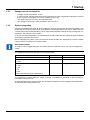
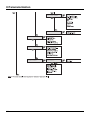
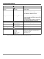
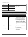
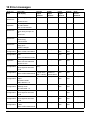
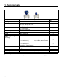
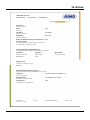
15
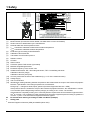
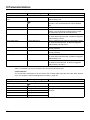
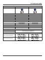
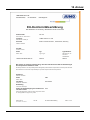
1 Safety
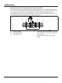
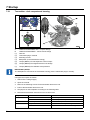
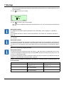
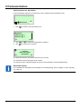
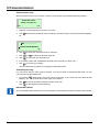
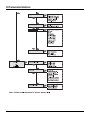
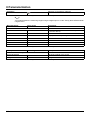
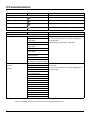
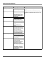
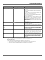
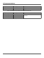
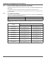
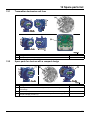
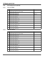
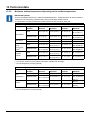
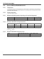
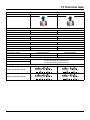
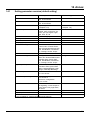
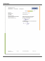
(1) Model number (for technical version details, see data sheet or order confirmation)
(2) Serial number for identification by the manufacturer
(3) Nominal width and nominal pressure levels
(4) Material: flange/lining/electrode
(5) Customer-specific TAG number (if provided)
(6) Tmed = Maximum admissible measurement medium temperature
Tamb = Maximum admissible ambient temperature
(7) Protection type according to DIN EN 60529
(8) Calibration value Qmax DN
(9) Calibration value Ss (range)
Calibration value Sz (zero point)
(10) Year of construction
(11) CE mark
(12) Order number
(13) Additional information: EE = Grounding electrodes, TFE = Partial filling electrode
(14) Accuracy with which the device was calibrated (e.g. 0.4 % of the measured value)
(15) Excitation frequency of the sensor coils
(16) Identification marking indicating whether the pressure device falls within the scope of the Pressure Equipment
Directive.aSpecification of the fluid group taken into consideration.
Fluid group 1 = Dangerous fluids, liquid, gaseous (Pressure Equipment Directive = PED)
If the pressure device is outside the scope of the Pressure Equipment Directivea, the classification is carried
out in the SEP (Sound Engineering Practice) category according to Art. 3 Para. 3 of the PED.
If the details are completely missing, then conformity with the requirements of the Pressure Equipment Direc-
tivea is not given. The exception for water networks and connection equipment parts according to guideline 1/
16 to art. 1. para. 3.2 of the Pressure Equipment Directive applies.
(17) Ex identification marking according to ATEX (example)
(18) Ex identification marking according to IECEx (example)
aPressure Equipment Directive (PED) 2014/68/EU (Mod. B+D).
=RQH
=RQH
=RQH
=RQH
=RQH
=RQH
*

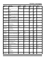
1 Safety
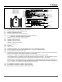
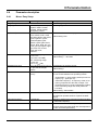
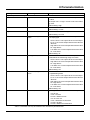
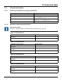
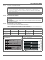
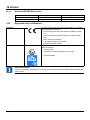
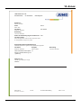
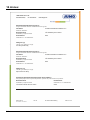
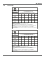
16
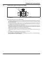
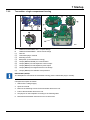
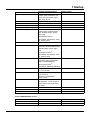
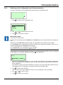
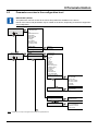
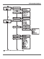
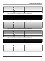
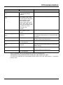
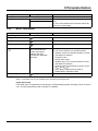
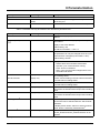
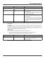
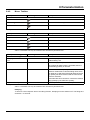
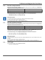
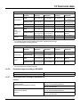
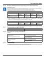
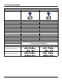
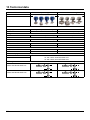
(1) Model number (for technical version details, see data sheet or order confirmation)
(2) Serial number for identification by the manufacturer
(3) Customer-specific TAG number (if provided)
(4) Tamb = Maximum admissible ambient temperature
(5) Protection type according to DIN EN 60529
(6) Voltage supply
(7) Transmitter communication protocol
(8) Software version
(9) Order number
(10) Revision status (xx.xx.xx)
(11) Ex identification marking according to ATEX (example)
*
=RQH
=RQH

17
1 Safety
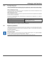
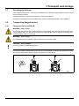
1.8 Transport safety information
Depending on the device, the unit may have an eccentric center of gravity.
The mounted protective screens or protective caps on the process connections for PTFE/PFA-lined de-
vices may only be removed immediately prior to installation. Make sure that the lining on the flange is
not cut or damaged here to avoid possible leaks.
1.9 Safety information for mounting
Observe the following notes:
• The flow direction must match the identification marking on the device see chapter 4.3.1 "Flow di-
rection", page 41.
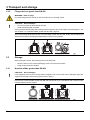
• the maximum torque for all flange screws must not be exceeded, see chapter 4.2 "Tightening
torques", page 35
• Install the devices without any mechanical tension (torsion, bending)
• Install the flanged/connection flange devices with plane-parallel counterflanges
• Only install devices for the designated operating conditions and with suitable seals
• In the event of pipeline vibrations, lock the flange nuts and bolts
A Nameplate
(1) Model number (for technical version details, see data sheet or order confirmation)
(2) Serial number for identification by the manufacturer
(3) Voltage supply
(4) Tamb = Maximum admissible ambient temperature
(5) Transmitter communication protocol
(6) CE mark
(7) Order number
(8) Customer-specific TAG number (if provided)
(9) Protection type according to DIN EN 60529
(10) Software version
W Ex identification marking according to ATEX and IECEx (example)
C Safety plate
Ä$³
Ä%³
Ä&³ *
Ä$³
Ä%³
Ä&³
=RQH
=RQH

1 Safety
18
1.10 Safety information for the electrical installation
The electrical connection must only be established by authorized qualified personnel according to the
electrical diagrams.
Observe the notes in the manual concerning the electrical connection. Otherwise, the electrical protec-
tion rating may be adversely affected.
The flow measuring system and the transmitter housing must be grounded.
The voltage supply line is installed according to the applicable national and international standards.
A separate fuse must be connected upstream in close proximity to each unit, and must be marked ac-
cordingly. The nominal current of the circuit breaker must not exceed 16 A.
The device protection rating is I and the overvoltage category is II (IEC 664).
The voltage supply and the electrical circuit for the sensor coils are electrical circuits that are dangerous
to touch.
The coil and signal circuit may only be connected with the corresponding sensors from the manufacturer.
The supplied cable must be used.
Only electrical circuits that do not pose a contact risk can be connected to the other signal inputs and
outputs.
1.11 Safety information for operation
When hot fluids flow through the unit, contact with the surface may result in burns.
Aggressive or corrosive fluids can cause damage to parts in contact with the medium. Pressurized fluids
can escape prematurely due to this.
Flange seal or process connection seal fatigue (e.g., aseptic compression fitting, Tri-Clamp, etc.) can
allow pressurized medium to escape.
When using internal flat seals, these can become brittle due to the CIP/SIP processes.
If pressure surges that exceed the device's admissible nominal pressure occur continuously during op-
eration, it can adversely affect the device's operating life.
WARNING – Personal injuries!
Bacteria and chemical substances can contaminate or pollute pipeline systems and their materials.

19
1 Safety
1.12 Technical limit values
The device is only designed for use within the technical limit values specified on the nameplate and in
the data sheets.
The following technical limit values must be observed:
• The admissible operating pressure (PS) and the admissible temperature (TS) must not exceed the
pressure temperature ratings (p/T ratings).
• The maximum operating temperature must not be exceeded
• The admissible ambient temperature must not be exceeded
• The housing protection type must be observed during use.
• The sensor must not be operated in the vicinity of powerful electromagnetic fields, e.g. motors,
pumps, transformers, etc. A minimum clearance of approx. 1 m (3.28 ft) must be maintained. When
mounting units on or to steel parts (e.g. steel brackets), a minimum clearance of 100 mm
(3.94 inches) must be maintained (these values were determined based on IEC 801-2 and
IEC TC77B).
1.13 Admissible measurement media
When using measurement media, the following points must be observed
• Measurement media (fluids) may only be used if it can be ensured through state-of-the-art technol-
ogy or the operating experience of the operator that the chemical and physical properties, which are
necessary to ensure operational security, of the transmitter parts (measuring electrode or grounding
electrodes, lining or connection parts or protective screen or protective flange) that come into contact
with the media are not affected during their service life.
• Measurement media with unknown properties or abrasive measurement media may only be used if
the operator can perform regular and suitable tests to ensure the safe condition of the device.
• The specifications on the nameplate must be observed.

1 Safety
20
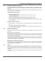
1.14 Safety information for inspections and maintenance
Maintenance work may only be performed by trained personnel.
• Before removing the device, depressurize the device and if necessary, the adjacent lines or contain-
ers.
• Before opening the device, check whether hazardous materials were used as a measurement me-
dium. There may be dangerous residual quantities in the device, which can leak when opened.
• If required as part of the operator's responsibility, the following points must be checked through reg-
ular inspections:
- The pressure-retaining walls/lining of the pressure device
- The measurement technology function
- The leak-tightness
- The wear (corrosion)
1.15 Returning devices
The following applies for returning devices for repairs or recalibration:
• Use the original packaging or suitably secure shipping containers
• Enclose the completed accompanying repair form with the device
The following also applies to devices that have come into contact with hazardous materials:
• Enclose the completed accompanying repair form and the declaration of decontamination with the
device
The hazardous materials must be rinsed out from all hollow spaces, such as between the measuring pipe
and housing, and neutralized. With sensors > DN 400, the service screw (for draining condensate fluid)
at the lower point of the housing must be opened to dispose of the hazardous materials and/or neutralize
the coil and electrode chamber.
These measures must be confirmed in writing in the declaration of decontamination.
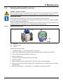
Return address and documents
WARNING – Danger to persons!
When the case lid is open, the EMC and touch protection are disabled. The housing contains electrical
circuits that are dangerous when touched. For this reason, the voltage supply must be switched off be-
fore opening the case lid.
WARNING – Danger to persons!
The inspection screw (for draining condensate liquid) with devices ≥ DN 450 may be pressurized. Spout-
ing medium can cause serious injuries.
Depressurize the pipeline before opening the inspection screw.
IMPORTANT (NOTE)!
According to EC guidelines for hazardous materials, the owner of hazardous waste is responsible for its
disposal or must observe the following regulations when shipping:
All devices delivered to the manufacturer must be free of any hazardous materials (acids, alkalis, sol-
vents, etc.).
IMPORTANT (NOTE)!
All documents important for the return as well as the return address of the manufacturer are available at
http://reparaturdienst.jumo.info.
Page is loading ...
Page is loading ...
Page is loading ...
Page is loading ...
Page is loading ...
Page is loading ...
Page is loading ...
Page is loading ...
Page is loading ...
Page is loading ...
Page is loading ...
Page is loading ...
Page is loading ...
Page is loading ...
Page is loading ...
Page is loading ...
Page is loading ...
Page is loading ...
Page is loading ...
Page is loading ...
Page is loading ...
Page is loading ...
Page is loading ...
Page is loading ...
Page is loading ...
Page is loading ...
Page is loading ...
Page is loading ...
Page is loading ...
Page is loading ...
Page is loading ...
Page is loading ...
Page is loading ...
Page is loading ...
Page is loading ...
Page is loading ...
Page is loading ...
Page is loading ...
Page is loading ...
Page is loading ...
Page is loading ...
Page is loading ...
Page is loading ...
Page is loading ...
Page is loading ...
Page is loading ...
Page is loading ...
Page is loading ...
Page is loading ...
Page is loading ...
Page is loading ...
Page is loading ...
Page is loading ...
Page is loading ...
Page is loading ...
Page is loading ...
Page is loading ...
Page is loading ...
Page is loading ...
Page is loading ...
Page is loading ...
Page is loading ...
Page is loading ...
Page is loading ...
Page is loading ...
Page is loading ...
Page is loading ...
Page is loading ...
Page is loading ...
Page is loading ...
Page is loading ...
Page is loading ...
Page is loading ...
Page is loading ...
Page is loading ...
Page is loading ...
Page is loading ...
Page is loading ...
Page is loading ...
Page is loading ...
Page is loading ...
Page is loading ...
Page is loading ...
Page is loading ...
Page is loading ...
Page is loading ...
Page is loading ...
Page is loading ...
Page is loading ...
Page is loading ...
Page is loading ...
Page is loading ...
Page is loading ...
Page is loading ...
Page is loading ...
Page is loading ...
Page is loading ...
Page is loading ...
Page is loading ...
Page is loading ...
Page is loading ...
Page is loading ...
Page is loading ...
Page is loading ...
Page is loading ...
Page is loading ...
Page is loading ...
Page is loading ...
Page is loading ...
Page is loading ...
Page is loading ...
Page is loading ...
Page is loading ...
Page is loading ...
Page is loading ...
Page is loading ...
Page is loading ...
Page is loading ...
Page is loading ...
Page is loading ...
Page is loading ...
Page is loading ...
Page is loading ...
Page is loading ...
Page is loading ...
Page is loading ...
Page is loading ...
Page is loading ...
Page is loading ...
Page is loading ...
Page is loading ...
Page is loading ...
Page is loading ...
Page is loading ...
Page is loading ...
Page is loading ...
Page is loading ...
Page is loading ...
Page is loading ...
Page is loading ...
Page is loading ...
Page is loading ...
Page is loading ...
Page is loading ...
Page is loading ...
Page is loading ...
Page is loading ...
Page is loading ...
Page is loading ...
Page is loading ...
Page is loading ...
Page is loading ...
Page is loading ...
Page is loading ...
Page is loading ...
Page is loading ...
Page is loading ...
Page is loading ...
Page is loading ...
Page is loading ...
Page is loading ...
Page is loading ...
Page is loading ...
Page is loading ...
Page is loading ...
Page is loading ...
Page is loading ...
Page is loading ...
Page is loading ...
Page is loading ...
Page is loading ...
Page is loading ...
Page is loading ...
Page is loading ...
Page is loading ...
Page is loading ...
Page is loading ...
Page is loading ...
Page is loading ...
Page is loading ...
Page is loading ...
Page is loading ...
Page is loading ...
Page is loading ...
Page is loading ...
Page is loading ...
Page is loading ...
Page is loading ...
Page is loading ...
Page is loading ...
Page is loading ...
Page is loading ...
Page is loading ...
Page is loading ...
Page is loading ...
Page is loading ...
Page is loading ...
Page is loading ...
Page is loading ...
Page is loading ...
Page is loading ...
Page is loading ...
Page is loading ...
Page is loading ...
Page is loading ...
Page is loading ...
Page is loading ...
Page is loading ...
Page is loading ...
Page is loading ...
Page is loading ...
Page is loading ...
Page is loading ...
Page is loading ...
Page is loading ...
Page is loading ...
Page is loading ...
Page is loading ...
Page is loading ...
Page is loading ...
Page is loading ...
Page is loading ...
Page is loading ...
Page is loading ...
Page is loading ...
Page is loading ...
Page is loading ...
Page is loading ...
Page is loading ...
Page is loading ...
Page is loading ...
Page is loading ...
Page is loading ...
Page is loading ...
Page is loading ...
Page is loading ...
Page is loading ...
Page is loading ...
Page is loading ...
Page is loading ...
-
 1
1
-
 2
2
-
 3
3
-
 4
4
-
 5
5
-
 6
6
-
 7
7
-
 8
8
-
 9
9
-
 10
10
-
 11
11
-
 12
12
-
 13
13
-
 14
14
-
 15
15
-
 16
16
-
 17
17
-
 18
18
-
 19
19
-
 20
20
-
 21
21
-
 22
22
-
 23
23
-
 24
24
-
 25
25
-
 26
26
-
 27
27
-
 28
28
-
 29
29
-
 30
30
-
 31
31
-
 32
32
-
 33
33
-
 34
34
-
 35
35
-
 36
36
-
 37
37
-
 38
38
-
 39
39
-
 40
40
-
 41
41
-
 42
42
-
 43
43
-
 44
44
-
 45
45
-
 46
46
-
 47
47
-
 48
48
-
 49
49
-
 50
50
-
 51
51
-
 52
52
-
 53
53
-
 54
54
-
 55
55
-
 56
56
-
 57
57
-
 58
58
-
 59
59
-
 60
60
-
 61
61
-
 62
62
-
 63
63
-
 64
64
-
 65
65
-
 66
66
-
 67
67
-
 68
68
-
 69
69
-
 70
70
-
 71
71
-
 72
72
-
 73
73
-
 74
74
-
 75
75
-
 76
76
-
 77
77
-
 78
78
-
 79
79
-
 80
80
-
 81
81
-
 82
82
-
 83
83
-
 84
84
-
 85
85
-
 86
86
-
 87
87
-
 88
88
-
 89
89
-
 90
90
-
 91
91
-
 92
92
-
 93
93
-
 94
94
-
 95
95
-
 96
96
-
 97
97
-
 98
98
-
 99
99
-
 100
100
-
 101
101
-
 102
102
-
 103
103
-
 104
104
-
 105
105
-
 106
106
-
 107
107
-
 108
108
-
 109
109
-
 110
110
-
 111
111
-
 112
112
-
 113
113
-
 114
114
-
 115
115
-
 116
116
-
 117
117
-
 118
118
-
 119
119
-
 120
120
-
 121
121
-
 122
122
-
 123
123
-
 124
124
-
 125
125
-
 126
126
-
 127
127
-
 128
128
-
 129
129
-
 130
130
-
 131
131
-
 132
132
-
 133
133
-
 134
134
-
 135
135
-
 136
136
-
 137
137
-
 138
138
-
 139
139
-
 140
140
-
 141
141
-
 142
142
-
 143
143
-
 144
144
-
 145
145
-
 146
146
-
 147
147
-
 148
148
-
 149
149
-
 150
150
-
 151
151
-
 152
152
-
 153
153
-
 154
154
-
 155
155
-
 156
156
-
 157
157
-
 158
158
-
 159
159
-
 160
160
-
 161
161
-
 162
162
-
 163
163
-
 164
164
-
 165
165
-
 166
166
-
 167
167
-
 168
168
-
 169
169
-
 170
170
-
 171
171
-
 172
172
-
 173
173
-
 174
174
-
 175
175
-
 176
176
-
 177
177
-
 178
178
-
 179
179
-
 180
180
-
 181
181
-
 182
182
-
 183
183
-
 184
184
-
 185
185
-
 186
186
-
 187
187
-
 188
188
-
 189
189
-
 190
190
-
 191
191
-
 192
192
-
 193
193
-
 194
194
-
 195
195
-
 196
196
-
 197
197
-
 198
198
-
 199
199
-
 200
200
-
 201
201
-
 202
202
-
 203
203
-
 204
204
-
 205
205
-
 206
206
-
 207
207
-
 208
208
-
 209
209
-
 210
210
-
 211
211
-
 212
212
-
 213
213
-
 214
214
-
 215
215
-
 216
216
-
 217
217
-
 218
218
-
 219
219
-
 220
220
-
 221
221
-
 222
222
-
 223
223
-
 224
224
-
 225
225
-
 226
226
-
 227
227
-
 228
228
-
 229
229
-
 230
230
-
 231
231
-
 232
232
-
 233
233
-
 234
234
-
 235
235
-
 236
236
-
 237
237
-
 238
238
-
 239
239
-
 240
240
-
 241
241
-
 242
242
-
 243
243
-
 244
244
-
 245
245
-
 246
246
-
 247
247
-
 248
248
-
 249
249
-
 250
250
-
 251
251
-
 252
252
-
 253
253
-
 254
254
-
 255
255
-
 256
256
-
 257
257
-
 258
258
-
 259
259
-
 260
260


JUMO flowTRANS MAG S01 Operating instructions
- Type
- Operating instructions
- This manual is also suitable for
Ask a question and I''ll find the answer in the document
Finding information in a document is now easier with AI
Related papers
-
JUMO AQUIS touch S Operating instructions
-
-
-
-
JUMO 707090 Operating instructions
-
-
-
-
-
Other documents
-
GHM OMNIPLUS RT Owner's manual
-
IFM PTU504 Operating instructions
-
IFM PT5500 Operating instructions
-
SAFATEX SIGMA ATEX 1000 User manual
-
-
Fluidwell F113-A-AP-H Series User manual
-
 Thermo Fisher Scientific Application User guide
-
-
Azbil 18B MTG14C (Converter) User manual
-
 Software s ScanMaster-ELM v2.1 User guide

