American Lighting 12-24V DMX 5 Channel RJ45 Decoder Installation guide

Type
Installation guide

American Lighting 12-24V DMX 5 Channel RJ45 Decoder is a versatile device designed for controlling various types of lighting fixtures using DMX signals. With its wide input voltage range of 12-24V DC and 5 independent output terminals rated for 8A each, it offers flexible power distribution for lighting setups. This decoder enables precise control of single color, Tunable CCT, RGB/RGBW, or RGB+Tunable CCT fixtures, making it suitable for a variety of applications.

American Lighting 12-24V DMX 5 Channel RJ45 Decoder is a versatile device designed for controlling various types of lighting fixtures using DMX signals. With its wide input voltage range of 12-24V DC and 5 independent output terminals rated for 8A each, it offers flexible power distribution for lighting setups. This decoder enables precise control of single color, Tunable CCT, RGB/RGBW, or RGB+Tunable CCT fixtures, making it suitable for a variety of applications.

Page 1 of 3 11775 E. 45th Ave. Denver, CO 80239 Ph: 1-800-880-1180 Fax: 303-695-7633
DMX 5 Channel RJ45 Decoder
INSTALLATION INSTRUCTIONS
REC-DMX-RJ45A-5CH
12-24V
©2022 American Lighting, Inc. REV2149 www.AmericanLighting.com
Pin1:Data+
Pin2:Data-
Pin7:GN D
Pin8:GN D
12345678
DMX
Female
Signal DMX Signa l
Male
DMX Signal
RJ4 5
3
2
V-
V-
V+
V+
1/R-
2/G-
3/B-
4/W1 -
5/W2 -
Back Ente rU pD own
D+
D-
D+
D-
GND
1
3
21
12345678
Pin1:GN D
Pin2:D -
Pin3:D +
Pin1:GND
Pin2:D -
Pin3:D +
DMX in/ ou t
DC Pow er
input
DMX in/ou tDMX in/ou t
SAFETY INFORMATION
Read all instructions before beginning; Save these instructions for future use.
To reduce the risk of fire, electric shock, or injury to person(s), pay close attention
to this manual and stay within its guidelines when using this product.
This receiver is rated IP20; avoid the sun and moisture.
Avoid using receiver in areas where extreme hot, cold, dust, or humidity exist.
This receiver is suitable for indoor, dry locations only.
Always be sure to mount this controller in an area with proper ventilation to
avoid overheating.
This product has an operating temperature range of -20°C to 50°C.
Never connect any cables while power is on and always ensure correct connections
to avoid short circuits prior to switching on. Ensure all wires and cables are secured
tightly in the connector prior to operation.
For cleaning, use a soft, dry or damp cloth. Do not use harsh chemicals or
abrasives.
This receiver is rated for 12-24V DC input with a maximum line-in of 20.5A.
This receiver has 5 output terminals rated for 8A/96-192W each.
These products may represent a possible shock or
fire hazard if improperly installed or attached in any
way. Products should be installed in accordance
with these instructions, current electrical codes,
and/or the current National Electric Code (NEC).
This receiver requires a 12-24V DC power
supply (LED-DR series driver recommended, sold
separately). Disconnect supply power at the source
prior to installation.
INSTALLING RECEIVER (SEE FIGURE 1):
This receiver requires a 12-24V DC power supply (sold separately).
This receiver requires a Trulux DMX controller (sold separately) or another auxiliary DMX master control (not included).
1. Determine desired location of receiver. Mounting tabs on either end of the receiver may be utilized to secure receiver in place via screws.
2. This receiver has 5 x 8A current output terminals that can be used with single color, Tunable CCT, RGB/RGBW, or RGB+Tunable CCT fixtures.
Wire the receiver to a fixture by following the fixture’s instruction manual and wiring diagrams, ensuring to match polarity (wiring varies
depending on product). Connect fixture prior to bringing any power to the system.
3. Bring 12-24V DC supply power to the receiver, matching polarity (See Figure 1).
Controllers and receivers may be powered
by the same driver on the secondary side
WARNING
WARNING
FIGURE 1
to 120V AC
12-24V DC
Power Supply
LN
DMX Master
Controller
D1
D1
GND
CH 5: W/WW output (-)
XLR3 Female
RJ45 Ports
XLR3 Male
CH 4: W/CW output (-)
CH 3: B/WW output (-)
CH 2: G/CW output (-)
CH 1: R/WW output (-)
Common Anode output (+)
+
-
Page 2 of 3 11775 E. 45th Ave. Denver, CO 80239 Ph: 1-800-880-1180 Fax: 303-695-7633
DMX 5 Channel RJ45 Decoder
INSTALLATION INSTRUCTIONS
REC-DMX-RJ45A-5CH
12-24V
©2022 American Lighting, Inc. REV2149 www.AmericanLighting.com
FIGURE 4
FIGURE 5
FIGURE 2
FIGURE 3
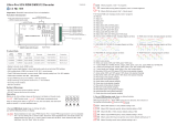
OPERATING DMX RECEIVER (SEE FIGURE 4):
This receiver requires a 12-24V DC power supply (sold separately).
1. This receiver can operate in Standalone Mode or Decoder Mode.
Before choosing any other setting, select which mode you wish
to operate: run1 for DMX Decoder Mode and run2 for Standalone
Mode.
2. Utilize the Up and Down buttons to toggle through menu selec-
tions.
3. Utilize the Enter button to select and the Back button to return to
main menu.
4. To restore factory default settings, press and hole both the Back
and Enter buttons until the digital display turns o, the release the
key. The system will reset and the digital display will turn on again
with all settings restored to default.
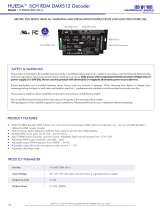
INTERCONNECTING RECEIVERS (SEE FIGURE 2):
This receiver requires a 12-36V DC power supply (LED-DR series driver
recommended, sold separately). This receiver requires a Trulux DMX
controller (sold separately) or another auxiliary DMX master control
(not included).
1. Interconnect DMX signal by connecting D - and D + from first
controller to D - and D + on second controller, matching polarity.
Then connect ground to ground on each. Continue for each
successive controller. See Figure 2.
2. Bring 12-24V DC supply power to each receiver in succession,
matching polarity. See Figure 2.
3. This receiver can also be inter-connected via XLR3 or RJ45 ports.
This requires the use of XLR3 or RJ45 cable (not included). See
Figure 1 and 3.
To Master DMX
Controller
To Fixture
Digital Display
Buttons
The micro dimming eect can only be visible when the dimming
curve gamma value is set lower than 1.4. The lower the value is, the
more visible the micro dimming eect will be.
1 2 3 4
1 = Back
2 = Enter
3 = Up
4 = Down
To 12-24V DC
Power Supply
+
GND
-
To
DMX master
control
Interconnecting via XLR3 Ports Interconnecting via RJ45 Ports
A.XXX DMX Address: Default 001
CHXX DMX Channel Quantity - Default CH05
CH01 = 1 DMX address: all output channels 001
CH02 = 2DMX address: output 1,3=001 & 2,4,5=002
CH03 = 3DMX address: output 1,2=001,002 & 3,4,5=003
CH04 = 4DMX address: output 1,2,3=001,002,003 & 4,5=004
CH05 = 5DMX address: output 1,2,3,4,5=001,002,003,004,005
btXX PWM Resolution: 8bit or 16bit - Default 16bit
PFXX PWM Frequency: 00~30 - Default 1kmHz
00=500Hz, 01=1kHz, 02=2kHz...30=30kHz
gAXX Dimming Curve Gamma Value: 0.1~9.9Default gA1.5
See Figure 5 for more information
dPXX Decoding Mode: Default dp1.1
1st X is DMX address qty, 2nd X is PWM channel qty
See page 3 for more information
Page 3 of 3 11775 E. 45th Ave. Denver, CO 80239 Ph: 1-800-880-1180 Fax: 303-695-7633
DMX 5 Channel RJ45 Decoder
INSTALLATION INSTRUCTIONS
REC-DMX-RJ45A-5CH
12-24V
©2022 American Lighting, Inc. REV2149 www.AmericanLighting.com
FCC Compliance Statement
This device complies with part 15 of the FCC Rules. Operation is subject to the following two conditions:
1. This device may not cause harmful interference, and
2. This device must accept any interference received, including interference that may cause undesired operation.
FCC WARNING
This equipment has been tested and found to comply with the limits for a Class B digital device, pursuant to Part 15 of the FCC Rules. These limits are designed to
provide reasonable protection against harmful interference in a residential installation. This equipment generates, uses and can radiate radio frequency energy
and, if not installed and used in accordance with the instructions, may cause harmful interference to radio communications. However, there is no guarantee that
interference will not occur in a particular installation. If this equipment does cause harmful interference to radio or television reception, which can be determined by
turning the equipment o and on, the user is encouraged to try to correct the interference by one or more of the following measures:
• Reorient or relocate the receiving antenna.
• Increase the separation between the equipment and the receiver.
• Connect the equipment into an outlet dierent from that to which the receiver is connected.
• Consult the dealer or an experienced radio/TV technician for help.
Any changes or modications not expressly approved by the party responsible for compliance could void the user’s authority to operate the equipment.
  • Page 1 1
  • Page 2 2
  • Page 3 3

American Lighting 12-24V DMX 5 Channel RJ45 Decoder Installation guide

Type
Installation guide

American Lighting 12-24V DMX 5 Channel RJ45 Decoder is a versatile device designed for controlling various types of lighting fixtures using DMX signals. With its wide input voltage range of 12-24V DC and 5 independent output terminals rated for 8A each, it offers flexible power distribution for lighting setups. This decoder enables precise control of single color, Tunable CCT, RGB/RGBW, or RGB+Tunable CCT fixtures, making it suitable for a variety of applications.

Ask a question and I''ll find the answer in the document

Finding information in a document is now easier with AI