ROBOTIQ 3-Finger Adaptive Robot Gripper User manual
- Category
- Robotics
- Type
- User manual


Table of Contents
Robotiq inc. © 2011 2
Revisions . . . . . . . . . . . . . . . . . . . . . . . . . . . . . . . . . . . . . . . . . . . . . . . . . . . . . . . . . . . . . . . . . . . . . . . . . . . . . . . . . . . . . . . . . . . . . . . . . . . . 3
1. General Presentation . . . . . . . . . . . . . . . . . . . . . . . . . . . . . . . . . . . . . . . . . . . . . . . . . . . . . . . . . . . . . . . . . . . . . . . . . . . . . . . . . . . . . . . . . 3
2. Safety . . . . . . . . . . . . . . . . . . . . . . . . . . . . . . . . . . . . . . . . . . . . . . . . . . . . . . . . . . . . . . . . . . . . . . . . . . . . . . . . . . . . . . . . . . . . . . . . . . . . . 8
2.1 Warning . . . . . . . . . . . . . . . . . . . . . . . . . . . . . . . . . . . . . . . . . . . . . . . . . . . . . . . . . . . . . . . . . . . . . . . . . . . . . . . . . . . . . . . . . . . . . . . 9
2.2 Intended use . . . . . . . . . . . . . . . . . . . . . . . . . . . . . . . . . . . . . . . . . . . . . . . . . . . . . . . . . . . . . . . . . . . . . . . . . . . . . . . . . . . . . . . . . . . 9
3. Installation . . . . . . . . . . . . . . . . . . . . . . . . . . . . . . . . . . . . . . . . . . . . . . . . . . . . . . . . . . . . . . . . . . . . . . . . . . . . . . . . . . . . . . . . . . . . . . . . . 9
3.1 Environmental and operating conditions . . . . . . . . . . . . . . . . . . . . . . . . . . . . . . . . . . . . . . . . . . . . . . . . . . . . . . . . . . . . . . . . . . . . . . 10
3.2 Mechanical connections . . . . . . . . . . . . . . . . . . . . . . . . . . . . . . . . . . . . . . . . . . . . . . . . . . . . . . . . . . . . . . . . . . . . . . . . . . . . . . . . . . 10
3.3 Power supply specifications . . . . . . . . . . . . . . . . . . . . . . . . . . . . . . . . . . . . . . . . . . . . . . . . . . . . . . . . . . . . . . . . . . . . . . . . . . . . . . . 11
3.4 Wiring . . . . . . . . . . . . . . . . . . . . . . . . . . . . . . . . . . . . . . . . . . . . . . . . . . . . . . . . . . . . . . . . . . . . . . . . . . . . . . . . . . . . . . . . . . . . . . . . 11
3.4.1 Power connection . . . . . . . . . . . . . . . . . . . . . . . . . . . . . . . . . . . . . . . . . . . . . . . . . . . . . . . . . . . . . . . . . . . . . . . . . . . . . . . . . . 12
3.4.2 Communication connection . . . . . . . . . . . . . . . . . . . . . . . . . . . . . . . . . . . . . . . . . . . . . . . . . . . . . . . . . . . . . . . . . . . . . . . . . . . 13
DeviceNet communication protocol . . . . . . . . . . . . . . . . . . . . . . . . . . . . . . . . . . . . . . . . . . . . . . . . . . . . . . . . . . . . . . . . . . . . . . 13
Real-time Ethernet communication protocol . . . . . . . . . . . . . . . . . . . . . . . . . . . . . . . . . . . . . . . . . . . . . . . . . . . . . . . . . . . . . . . 15
Serial communication protocol . . . . . . . . . . . . . . . . . . . . . . . . . . . . . . . . . . . . . . . . . . . . . . . . . . . . . . . . . . . . . . . . . . . . . . . . . . 17
4. Control . . . . . . . . . . . . . . . . . . . . . . . . . . . . . . . . . . . . . . . . . . . . . . . . . . . . . . . . . . . . . . . . . . . . . . . . . . . . . . . . . . . . . . . . . . . . . . . . . . . . 18
4.1 Generalities . . . . . . . . . . . . . . . . . . . . . . . . . . . . . . . . . . . . . . . . . . . . . . . . . . . . . . . . . . . . . . . . . . . . . . . . . . . . . . . . . . . . . . . . . . . . 19
4.2 Status overview . . . . . . . . . . . . . . . . . . . . . . . . . . . . . . . . . . . . . . . . . . . . . . . . . . . . . . . . . . . . . . . . . . . . . . . . . . . . . . . . . . . . . . . . . 19
4.3 Control overview . . . . . . . . . . . . . . . . . . . . . . . . . . . . . . . . . . . . . . . . . . . . . . . . . . . . . . . . . . . . . . . . . . . . . . . . . . . . . . . . . . . . . . . . 19
4.4 Status LEDs . . . . . . . . . . . . . . . . . . . . . . . . . . . . . . . . . . . . . . . . . . . . . . . . . . . . . . . . . . . . . . . . . . . . . . . . . . . . . . . . . . . . . . . . . . . 20
4.4.1 Supply LED . . . . . . . . . . . . . . . . . . . . . . . . . . . . . . . . . . . . . . . . . . . . . . . . . . . . . . . . . . . . . . . . . . . . . . . . . . . . . . . . . . . . . . . 20
4.4.2 Communication LED . . . . . . . . . . . . . . . . . . . . . . . . . . . . . . . . . . . . . . . . . . . . . . . . . . . . . . . . . . . . . . . . . . . . . . . . . . . . . . . . 21
4.4.3 Fault LED . . . . . . . . . . . . . . . . . . . . . . . . . . . . . . . . . . . . . . . . . . . . . . . . . . . . . . . . . . . . . . . . . . . . . . . . . . . . . . . . . . . . . . . . . 21
4.5 Gripper register mapping . . . . . . . . . . . . . . . . . . . . . . . . . . . . . . . . . . . . . . . . . . . . . . . . . . . . . . . . . . . . . . . . . . . . . . . . . . . . . . . . . 22
4.5 Gripper register mapping (firmware version 3.0) . . . . . . . . . . . . . . . . . . . . . . . . . . . . . . . . . . . . . . . . . . . . . . . . . . . . . . . . . . . . . . . . 22
4.6 Robot output registers & functionalities . . . . . . . . . . . . . . . . . . . . . . . . . . . . . . . . . . . . . . . . . . . . . . . . . . . . . . . . . . . . . . . . . . . . . . . 24
4.7 Robot input registers & status . . . . . . . . . . . . . . . . . . . . . . . . . . . . . . . . . . . . . . . . . . . . . . . . . . . . . . . . . . . . . . . . . . . . . . . . . . . . . . 27
4.8 Example . . . . . . . . . . . . . . . . . . . . . . . . . . . . . . . . . . . . . . . . . . . . . . . . . . . . . . . . . . . . . . . . . . . . . . . . . . . . . . . . . . . . . . . . . . . . . . 30
4.9 MODBUS RTU communication protocol . . . . . . . . . . . . . . . . . . . . . . . . . . . . . . . . . . . . . . . . . . . . . . . . . . . . . . . . . . . . . . . . . . . . . . 31
4.9.1 Connection setup . . . . . . . . . . . . . . . . . . . . . . . . . . . . . . . . . . . . . . . . . . . . . . . . . . . . . . . . . . . . . . . . . . . . . . . . . . . . . . . . . . . 31
4.9.2 Read holding registers (FC03) . . . . . . . . . . . . . . . . . . . . . . . . . . . . . . . . . . . . . . . . . . . . . . . . . . . . . . . . . . . . . . . . . . . . . . . . 31
4.9.3 Preset single register (FC06) . . . . . . . . . . . . . . . . . . . . . . . . . . . . . . . . . . . . . . . . . . . . . . . . . . . . . . . . . . . . . . . . . . . . . . . . . . 32
4.9.4 Preset multiple registers (FC16) . . . . . . . . . . . . . . . . . . . . . . . . . . . . . . . . . . . . . . . . . . . . . . . . . . . . . . . . . . . . . . . . . . . . . . . 32
4.10 MODBUS TCP communication protocol . . . . . . . . . . . . . . . . . . . . . . . . . . . . . . . . . . . . . . . . . . . . . . . . . . . . . . . . . . . . . . . . . . . . . 33
4.10.1 Connection Setup . . . . . . . . . . . . . . . . . . . . . . . . . . . . . . . . . . . . . . . . . . . . . . . . . . . . . . . . . . . . . . . . . . . . . . . . . . . . . . . . . 33
4.10.2 Read Input Registers (FC04) . . . . . . . . . . . . . . . . . . . . . . . . . . . . . . . . . . . . . . . . . . . . . . . . . . . . . . . . . . . . . . . . . . . . . . . . . 34
4.10.3 Preset Multiple Registers (FC16) . . . . . . . . . . . . . . . . . . . . . . . . . . . . . . . . . . . . . . . . . . . . . . . . . . . . . . . . . . . . . . . . . . . . . 34
5. User Interface . . . . . . . . . . . . . . . . . . . . . . . . . . . . . . . . . . . . . . . . . . . . . . . . . . . . . . . . . . . . . . . . . . . . . . . . . . . . . . . . . . . . . . . . . . . . . . 35
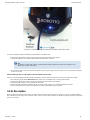
5.1 Requirements . . . . . . . . . . . . . . . . . . . . . . . . . . . . . . . . . . . . . . . . . . . . . . . . . . . . . . . . . . . . . . . . . . . . . . . . . . . . . . . . . . . . . . . . . . 36
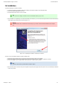
5.2 Installation . . . . . . . . . . . . . . . . . . . . . . . . . . . . . . . . . . . . . . . . . . . . . . . . . . . . . . . . . . . . . . . . . . . . . . . . . . . . . . . . . . . . . . . . . . . . . 36
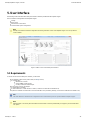
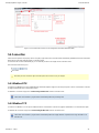
5.3 UI Description . . . . . . . . . . . . . . . . . . . . . . . . . . . . . . . . . . . . . . . . . . . . . . . . . . . . . . . . . . . . . . . . . . . . . . . . . . . . . . . . . . . . . . . . . . 38
5.4 Connection . . . . . . . . . . . . . . . . . . . . . . . . . . . . . . . . . . . . . . . . . . . . . . . . . . . . . . . . . . . . . . . . . . . . . . . . . . . . . . . . . . . . . . . . . . . . 40
5.4.1 Modbus RTU . . . . . . . . . . . . . . . . . . . . . . . . . . . . . . . . . . . . . . . . . . . . . . . . . . . . . . . . . . . . . . . . . . . . . . . . . . . . . . . . . . . . . . 40
5.4.2 Modbus TCP . . . . . . . . . . . . . . . . . . . . . . . . . . . . . . . . . . . . . . . . . . . . . . . . . . . . . . . . . . . . . . . . . . . . . . . . . . . . . . . . . . . . . . 40
5.5 Control of the Adaptive Gripper . . . . . . . . . . . . . . . . . . . . . . . . . . . . . . . . . . . . . . . . . . . . . . . . . . . . . . . . . . . . . . . . . . . . . . . . . . . . . 41
5.5.1 Initialization & Gripper Status . . . . . . . . . . . . . . . . . . . . . . . . . . . . . . . . . . . . . . . . . . . . . . . . . . . . . . . . . . . . . . . . . . . . . . . . . 41
5.5.2 Interface Options . . . . . . . . . . . . . . . . . . . . . . . . . . . . . . . . . . . . . . . . . . . . . . . . . . . . . . . . . . . . . . . . . . . . . . . . . . . . . . . . . . . 41
5.5.3 Operation Mode . . . . . . . . . . . . . . . . . . . . . . . . . . . . . . . . . . . . . . . . . . . . . . . . . . . . . . . . . . . . . . . . . . . . . . . . . . . . . . . . . . . . 42
5.5.4 Action . . . . . . . . . . . . . . . . . . . . . . . . . . . . . . . . . . . . . . . . . . . . . . . . . . . . . . . . . . . . . . . . . . . . . . . . . . . . . . . . . . . . . . . . . . . . 42
5.5.5 Control Parameters . . . . . . . . . . . . . . . . . . . . . . . . . . . . . . . . . . . . . . . . . . . . . . . . . . . . . . . . . . . . . . . . . . . . . . . . . . . . . . . . . 42
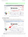
5.5.6 Gripper Feedback . . . . . . . . . . . . . . . . . . . . . . . . . . . . . . . . . . . . . . . . . . . . . . . . . . . . . . . . . . . . . . . . . . . . . . . . . . . . . . . . . . 43
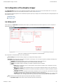
5.6 Configuration of the Adaptive Gripper . . . . . . . . . . . . . . . . . . . . . . . . . . . . . . . . . . . . . . . . . . . . . . . . . . . . . . . . . . . . . . . . . . . . . . . . 45
5.6.1 Ethernet IP . . . . . . . . . . . . . . . . . . . . . . . . . . . . . . . . . . . . . . . . . . . . . . . . . . . . . . . . . . . . . . . . . . . . . . . . . . . . . . . . . . . . . . . . 45
5.6.2 Modbus TCP . . . . . . . . . . . . . . . . . . . . . . . . . . . . . . . . . . . . . . . . . . . . . . . . . . . . . . . . . . . . . . . . . . . . . . . . . . . . . . . . . . . . . . 46
5.6.3 DeviceNet . . . . . . . . . . . . . . . . . . . . . . . . . . . . . . . . . . . . . . . . . . . . . . . . . . . . . . . . . . . . . . . . . . . . . . . . . . . . . . . . . . . . . . . . 48
5.7 Menu Options . . . . . . . . . . . . . . . . . . . . . . . . . . . . . . . . . . . . . . . . . . . . . . . . . . . . . . . . . . . . . . . . . . . . . . . . . . . . . . . . . . . . . . . . . . 50
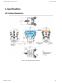
6. Specifications . . . . . . . . . . . . . . . . . . . . . . . . . . . . . . . . . . . . . . . . . . . . . . . . . . . . . . . . . . . . . . . . . . . . . . . . . . . . . . . . . . . . . . . . . . . . . . . 50
6.1 Technical dimensions . . . . . . . . . . . . . . . . . . . . . . . . . . . . . . . . . . . . . . . . . . . . . . . . . . . . . . . . . . . . . . . . . . . . . . . . . . . . . . . . . . . . 51
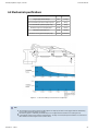
6.2 Mechanical specifications . . . . . . . . . . . . . . . . . . . . . . . . . . . . . . . . . . . . . . . . . . . . . . . . . . . . . . . . . . . . . . . . . . . . . . . . . . . . . . . . . 52
7. Maintance and service . . . . . . . . . . . . . . . . . . . . . . . . . . . . . . . . . . . . . . . . . . . . . . . . . . . . . . . . . . . . . . . . . . . . . . . . . . . . . . . . . 53
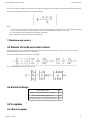
6.3 Moment of inertia and center of mass . . . . . . . . . . . . . . . . . . . . . . . . . . . . . . . . . . . . . . . . . . . . . . . . . . . . . . . . . . . . . . . . . . . . . . . . 53
6.4 Electrical ratings . . . . . . . . . . . . . . . . . . . . . . . . . . . . . . . . . . . . . . . . . . . . . . . . . . . . . . . . . . . . . . . . . . . . . . . . . . . . . . . . . . . . . . . . 53
6.5 Faceplates . . . . . . . . . . . . . . . . . . . . . . . . . . . . . . . . . . . . . . . . . . . . . . . . . . . . . . . . . . . . . . . . . . . . . . . . . . . . . . . . . . . . . . . . . . . . . 53
6.5.1 Blank faceplate . . . . . . . . . . . . . . . . . . . . . . . . . . . . . . . . . . . . . . . . . . . . . . . . . . . . . . . . . . . . . . . . . . . . . . . . . . . . . . . . . . . . 53
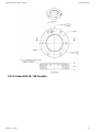
6.5.2 Yaskawa SDA-5D_10D faceplate . . . . . . . . . . . . . . . . . . . . . . . . . . . . . . . . . . . . . . . . . . . . . . . . . . . . . . . . . . . . . . . . . . . . . . 54
7. Warranty . . . . . . . . . . . . . . . . . . . . . . . . . . . . . . . . . . . . . . . . . . . . . . . . . . . . . . . . . . . . . . . . . . . . . . . . . . . . . . . . . . . . . . . . . . . . . . . . . . 55
8. Contact . . . . . . . . . . . . . . . . . . . . . . . . . . . . . . . . . . . . . . . . . . . . . . . . . . . . . . . . . . . . . . . . . . . . . . . . . . . . . . . . . . . . . . . . . . . . . . . . . . . . 56

Robotiq Adaptative Gripper, S model Instruction Manual
Robotiq inc. © 2011 3
Revisions
Robotiq may modify this product without notice, when necessary, due to product improvements, modifications or changes in specifications. If such
modification is made, the manual will also be revised, see revision information. See the latest version of this manual online at
. http://support.robotiq.com/
Revision 111031
Sections added: User Interface and MODBUS TCP communication protocol
Revision 110515
Manual release
Copyright
© 2011 Robotiq Inc. All rights reserved.
This manual, and the product it describes, are protected by the Copyright Act of Canada, by laws of other countries, and by international treaties,
and therefore may not be reproduced in whole or in part, whether for sale or not, without prior written consent from Robotiq. Under copyright law,
copying includes translation into another language or format.
Information provided by Robotiq in this document is believed to be accurate and reliable. However, no responsibility is assumed by Robotiq for its
use. There may be some differences between the manual and the product if the product has been modified after the edition date.
The information contained in this document is subject to change without notice.

Robotiq Adaptative Gripper, S model Instruction Manual
Robotiq inc. © 2011 4
1. General Presentation
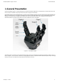
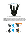
The Robotiq Adaptive Gripper is a robotic peripheral that is designed for industrial applications. Its design makes it a unique robotic end-of-arm
tool to pick, place and handle a large range and volume of parts of varying sizes and shapes.
The Adaptive Gripper has three articulated fingers, i.e. finger A in front of finger B and finger C, that each have three joints (three phalanxes per
finger), as shown in Figure 1.1. The gripper can engage up to ten points of contact with objects (three on each of the phalanges plus the palm).
The fingers are under-actuated, meaning they have fewer motors than the total number of joints. This configuration allows the fingers to
automatically adapt to the shape of object they grip and it also simplifies the control of the gripper.
Figure 1.1 – The Adaptive Gripper.
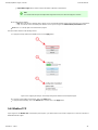
Two different types of movements can be performed with the gripper. The first one simultaneously changes the orientation of fingers B and C as
shown in Figure 1.2. That movement is referred to as changing Operation Modes. The Operation Mode is determined by the user prior to the grip
in function of the size or the shape of the object and for the task that has to be done.

Robotiq Adaptative Gripper, S model Instruction Manual
Robotiq inc. © 2011 5
1.
2.
3.
4.
Figure 1.2 – First type of movement of the Adaptive Gripper: changing the Operation Mode
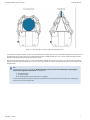
The is the most versatile Operation Mode. It is best suited for objects that have one dimension longer than the two othersbasic mode
but can grip a large variety of objects.
The is optimal for gripping round or large objects.wide mode
The is used for small objects that have to be picked precisely. This Operation Mode can only grip objects between the distalpinch mode
phalanxes of the fingers.
The is used primarily for tiny objects. This mode is not very powerful but is precise. In scissor mode, it is not possible toscissor mode
surround an object. Here, fingers B and C move laterally towards each other while finger A remains still.
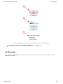
The four pre-set Operation Modes can be chosen by the user (see Figure 1.3).
Figure 1.3 – The four Operation Modes of the Adaptive Gripper.

Robotiq Adaptative Gripper, S model Instruction Manual
Robotiq inc. © 2011 6
The second movement of the gripper is the closing and opening of the fingers as shown in Figure 1.4. This action is performed with a single input
from a user. Each finger is not controlled independently; the gripper itself closes each finger until it reaches a stable configuration, on an object or
against the gripper palm. Note that a user can specify the relative speed at which the fingers will close and the relative force that will be applied to
an object.
Figure 1.4 – Second movement of the Adaptive Gripper: closing and opening the fingers.
Two types of grips occur when closing the Adaptive Gripper on an object: Fingertip Grip or Encompassing Grip.
The is when an object is only held by the distal phalanxes. This type of grip is similar to what is done with conventionalFingertip Grip
industrial parallel grippers. In this situation, the stability of the grip is mainly related to the friction between the fingers and the object.
The is when the fingers surround an object. The object is encompassed within the fingers and the stability of theEncompassing Grip
grip is no longer related to friction. We suggest using the Encompassing Grip whenever possible to increase grip stability. Figure 1.5
shows the two types of grips.

Robotiq Adaptative Gripper, S model Instruction Manual
Robotiq inc. © 2011 7
Figure 1.5 – The Two Types of Grip: Encompassing and Fingertip Grips.
It is important to note that a Fingertip Grip can only be performed when the fingers touch the object with the distal phalanxes first. Inversely, for an
Encompassing Grip, the fingers must touch the object with the proximal or medial phalanxes first. Also, to ensure stability, the object should be
held against the gripper palm before doing an Encompassing Grip.
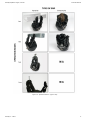
Note that the Encompassing Grip cannot occur in all Operation Modes. Thereby, in Pinch and Scissor modes, it is only possible to do Fingertip
Gripping. On the other side, the Fingertip Grip can occur in all four Operation Modes. Figure 1.6 summarizes the Types of Grip possible for each
Operation Mode.
Info
Operation Modes are inputs to the gripper. Whether the fingers close to produce an Encompassing or Fingertip grip is
. It will depend on:decided at the gripper level automatically
The Operation Mode;
The part's geometry;
The relative position of the part with respect to the gripper.
In other words, picking the same part using the same Operation Mode could result in either an encompassing or fingertip grip
based on a part's position and geometry.

Robotiq Adaptative Gripper, S model Instruction Manual
Robotiq inc. © 2011 8
Figure 1.6 – Operation Modes vs. Types of Grip.

Robotiq Adaptative Gripper, S model Instruction Manual
Robotiq inc. © 2011 9
2. Safety
Warning
Read this section carefully before installation, operation, maintenance or inspection of the Robotiq Adaptive Gripper.
This documentation explains the various components of the Adaptive Gripper and general operation. Read this documentation and be sure to
understand its contents before handling the Adaptive Gripper.
The drawings and photos in this documentation are representative examples and differences may exist between them and the delivered product.
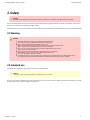
2.1 Warning
Warning
The gripper needs to be properly secured before operating the robot.
Do not install or operate a gripper that is damaged or lacking parts.
Never supply the gripper with an alternative current source.
Make sure all cord sets are always secured at both ends, at the gripper and at the robot.
Always respect the recommended keying for electrical connections.
Be sure no one is in the robot and gripper path before initializing the robot's routine.
Always respect the gripper payload.
Set the gripper pinch force and speed accordingly, based on your application.
Keep fingers and clothes away from the gripper while the power is on.
Do not use the gripper on people or animals.
For welding applications, make sure there are no gripper parts on the ground path of the welding power source.
Any usage of the gripper beyond these definitions is inappropriate and may cause injury or damage.
2.2 Intended use
The gripper unit is designed for gripping and temporary secure holding of parts.
Caution
The gripper is NOT intended for applying force against objects or surfaces.
The unit may be used only within the range of its technical data. Any other use of the product is deemed improper and unintended use. Robotiq
will not be liable for any damages resulting from improper use.

Robotiq Adaptative Gripper, S model Instruction Manual
Robotiq inc. © 2011 10
1.
2.
3.
3. Installation
Warning
Be sure to read and understand the related to the Adaptive Griper prior to installation.safety instructions
Warning
Do not operate the gripper, or even turn on the power supply, before it is firmly anchored. The gripper fingers may move and
cause injury or damage.
3.1 Environmental and operating conditions
The gripper is designed for industrial applications. Always respect the specified storage and operating environment conditions:
Minimum storage/transit temperature -22°F [-30°C]
Maximum storage/transit temperature 140°F [60°C]
Minimum operating temperature 14°F [-10°C]
Maximum operating temperature 122°F [50°C]
Humidity (non-condensing) 20-80% RH
Vibration < 0.5G
Others Free from dust, soot or water
Free from corrosive gases, liquids or explosive gases
Free from powerful electromagnetic interference sources
3.2 Mechanical connections
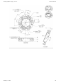
You must use a faceplate to attach the gripper to the robot. Be sure to use the faceplate related to your robot model. If there is no faceplate for
your robot, you can modify a blank faceplate model or Robotiq can create a custom version for you. (Please refer to the Faceplate Specification
for details on different faceplate models) Section
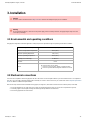
Here are the steps to follow for the installation of the gripper (see Figure 3.1). Note that all screws must be locked in place (Loctite 248).
Screw the faceplate to your robot arm (if your cables are running through the robot, be sure to use a faceplate with a groove).
Insert the gripper in the faceplate and align the indexing dowel pin with the associated hole.
Secure the gripper with the radial screws.

Robotiq Adaptative Gripper, S model Instruction Manual
Robotiq inc. © 2011 11
3.
Figure 3.1 – Attaching the Adaptive Gripper to a robot arm with the Faceplate.
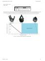
3.3 Power supply specifications
The gripper needs to be supplied by a DC voltage source. This power supply is not included with the gripper. The following table shows the
specifications regarding the power supply required to operate the gripper properly.
Output voltage 24 V DC
Output current 2 A
Ripple 2-3 % peak-peak
Output regulation 2% maximum
Overcurrent 4 A fuse at 77°F [25 C]
o
Maximum fuse I t factor
2100 A s at 77°F [25 C]
2 o
Overvoltage protection Not required1
1 The gripper has built-in overvoltage protection.
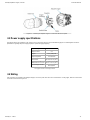
3.4 Wiring
Two connections are needed for the Adaptive Gripper, one for the power and one for the communication. On the gripper, both are located on the
Connection Panel shown in Figure 3.2.

Robotiq Adaptative Gripper, S model Instruction Manual
Robotiq inc. © 2011 12
Figure 3.2 – Power and Communication receptacles and connectors.
Warning
Use proper cabling management. Be sure to have enough forgiveness in the cabling to allow movement of the gripper along all
axes without pulling out the connectors.
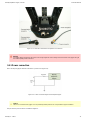
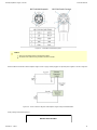
3.4.1 Power connection
Here is the way the gripper should be connected to a power source (Figure 3.3).
Figure 3.3 – Power connection diagram of the Adaptive Gripper.
Caution
The 4A fuse is external to the gripper. It is not provided by Robotiq and the user is responsible for proper installation.
The pin-out of the power connectors is detailed in Figure 3.4.

Robotiq Adaptative Gripper, S model Instruction Manual
Robotiq inc. © 2011 13
Figure 3.4 – Gripper Power Inlet and Power Connector.
The gripper should be supplied with cables that have the following specifications:
#22 AWG TEW, 300 V or 600 V.
3 Conductors, 2 for the supply and one for the protective ground.
Shielding, depending on the application. Shield must be grounded in robot controller.
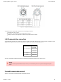
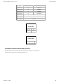
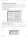
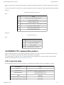
3.4.2 Communication connection
The following table summarizes the communication protocols available for the gripper. Note that only one protocol option is available in a given
gripper unit. The gripper that you have was configured before shipment with only one of the following protocols.
Family Protocol
Real-Time-Ethernet
EtherNet/IP
Modbus TCP/IP
EtherCAT
Fieldbus DeviceNet
Serial Modbus RTU
The same communication cable and connectors are used for all the protocols but each protocol has its own pin-out.
Warning
Be sure to use the appropriate cables and pin-outs for your communication protocol as any other setup may damage the
gripper.
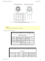
DeviceNet communication protocol
Figure 3.5 shows the pin-out for the DeviceNet communication protocol.

Robotiq Adaptative Gripper, S model Instruction Manual
Robotiq inc. © 2011 14
Figure 3.5 – DeviceNet communication pinout.
Caution
There is no terminating resistor mounted in the gripper.
The shield of the cable must be grounded in the robot controller.
The DeviceNet communication and the Adaptive Gripper use 24 V supply. Robotiq suggests to separate power supplies as shown in Figure 3.6.
Figure 3.6 – Power connection diagram of the Adaptive Gripper using DeviceNet Fieldbus.
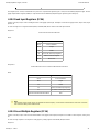
Factory settings for DeviceNet protocol:
IDENTIFICATION SETTINGS

Robotiq Adaptative Gripper, S model Instruction Manual
Robotiq inc. © 2011 15
Info Decimal value (base 10) Hexadecimal value (base 16)
Vendor ID : 283 0x0000011B
Product Code : 35 0x00000023
Serial Number : 0 0x00000000
Product Type : 12 0x0000000C
Major Revision : 1
Minor Revision : 1
Product Name : AG-DNS
BUS SETTING
MAC ID : 11
Baud Rate : 250 kBaud
DATA SETTINGS
Prod. Data Length : 12
Cons. Data Length : 12
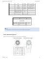
Real-time Ethernet communication protocol
Real-time Ethernet communication includes Ethernet/IP, EtherCAT and Modbus TCP/IP protocols.
See the Real-Time Ethernet pin-out diagram below (Figure 3.7).

Robotiq Adaptative Gripper, S model Instruction Manual
Robotiq inc. © 2011 16
Figure 3.7 – Real-time Ethernet communication pin-out.
Caution
The crossover on the RX/TX signals is made inside the gripper.
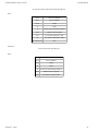
Factory settings for each Ethernet protocols:
EtherCat EtherNet/IP Modbus TCP/IP
IDENTIFICATION SETTINGS
Vendor ID : 0xE0000044 Vendor ID : 0x0000011B N / A
Product Code : 0x0000000B Product Code : 0x0000010D
Serial Number : 0x00000000 Product Type : 0x0000000C
Revision Number : 0x00000000 Major Revision : 1
Minor Revision : 1
Device Name : AG-EIS
EtherCat EtherNet/IP Modbus TCP/IP
BUS SETTING
N / A (see info note) IP Address : 192.168.1.11 IP Address : 192.168.1.11
Netmask : 255.255.255.0 Netmask : 255.255.255.0
Gateway : Disabled Gateway : Disabled

Robotiq Adaptative Gripper, S model Instruction Manual
Robotiq inc. © 2011 17
BootP : Disabled BootP : Disabled
DHCP : Disabled DHCP : Disabled
100Mbit : Enabled 100Mbit always on
Full Duplex: Enabled Full Duplex always on
Auto-neg : Enabled Auto-neg always on
Assembly Instance (input) : 101
Assembly Instance (output) : 100
Configuraton Instance : 1
Connection Type : Run/Idle Header
EtherCat EtherNet/IP Modbus TCP/IP
DATA SETTINGS
Input Data Bytes : 12 Prod. Data Length : 16 N / A
Output Data Bytes : 12 Cons. Data Length : 16 N / A
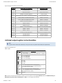
Info
Ethercat protocol uses inherent dynamic addressing thus bus settings cannot be customized
Serial communication protocol
Figure 3.8 shows the pin-out of the communication connectors when used in serial mode.


Robotiq Adaptative Gripper, S model Instruction Manual
Robotiq inc. © 2011 19
4. Control
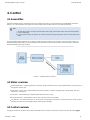
4.1 Generalities
The Robotiq Adaptive Gripper is controlled from the robot controller (see Figure 4.1) using an industrial protocol (EtherNet/IP, DeviceNet,
EtherCat, etc.). The programming of the gripper can be done with the of the robot or by offline programming.Teach Pendant
Info
The three fingers always close/open at the same time with a single command (the motion of each mechanical phalanx
is done automatically).
For each Operation Mode, the operator can control the partial closing / opening position, the force and the speed of the
fingers.
Since the Robotiq Adaptive Gripper has its own internal controller, high-level commands such as or are used to control it. TheOpen Close
embedded Robotiq Controller takes care of the regulation of the speed and the force prescribed, while the mechanical design of the fingers
automatically adapts to the shape of objects.
Figure 4.1 – Adaptive Gripper connections.
4.2 Status overview
Global Gripper Status - A global Gripper Status is available. This gives information such as which Operation Mode is currently active or if
the gripper is closed or open.
Object Status - There is also an Object Status that let you know if there is an object in the gripper and, in the affirmative, how many
fingers are in contact with it.
Fault Status - The Fault Status gives additional details about the cause of a fault_._
Motor Encoder Status - The information of the encoders of the four motors is also available.
Current Status - The current of the motors can also be known. Since the torque of the motor is a linear function of the current, this gives
information about the force that is applied at the actuation linkage of the finger.
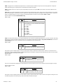
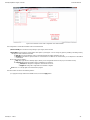
4.3 Control overview
The gripper controller has an internal memory that is shared with the robot controller. One part of the memory is for the robot output, gripper

Robotiq Adaptative Gripper, S model Instruction Manual
Robotiq inc. © 2011 20
1.
2.
. The other part of the memory is for the robot input, (see Figure 4.2). Two types of actions can then be done byfunctionalities gripper status
the robot controller:
Write in the registers to activate ;robot output functionalities
Read in the registers to get the of the gripper. robot input status
Note that the gripper must be initialized at power on. This procedure takes a few seconds and allows the gripper to be calibrated against
internal mechanical stops.
Figure 4.2 – Gripper memory shared with the robot controller.
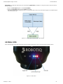
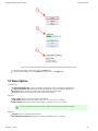
4.4 Status LEDs
Three status LED lights provide general information about the Adaptive Gripper Status. Figure 4.3 shows the LEDs and their locations.
Figure 4.3 – Status LEDs.
Page is loading ...
Page is loading ...
Page is loading ...
Page is loading ...
Page is loading ...
Page is loading ...
Page is loading ...
Page is loading ...
Page is loading ...
Page is loading ...
Page is loading ...
Page is loading ...
Page is loading ...
Page is loading ...
Page is loading ...
Page is loading ...
Page is loading ...
Page is loading ...
Page is loading ...
Page is loading ...
Page is loading ...
Page is loading ...
Page is loading ...
Page is loading ...
Page is loading ...
Page is loading ...
Page is loading ...
Page is loading ...
Page is loading ...
Page is loading ...
Page is loading ...
Page is loading ...
Page is loading ...
Page is loading ...
Page is loading ...
Page is loading ...
Page is loading ...
-
 1
1
-
 2
2
-
 3
3
-
 4
4
-
 5
5
-
 6
6
-
 7
7
-
 8
8
-
 9
9
-
 10
10
-
 11
11
-
 12
12
-
 13
13
-
 14
14
-
 15
15
-
 16
16
-
 17
17
-
 18
18
-
 19
19
-
 20
20
-
 21
21
-
 22
22
-
 23
23
-
 24
24
-
 25
25
-
 26
26
-
 27
27
-
 28
28
-
 29
29
-
 30
30
-
 31
31
-
 32
32
-
 33
33
-
 34
34
-
 35
35
-
 36
36
-
 37
37
-
 38
38
-
 39
39
-
 40
40
-
 41
41
-
 42
42
-
 43
43
-
 44
44
-
 45
45
-
 46
46
-
 47
47
-
 48
48
-
 49
49
-
 50
50
-
 51
51
-
 52
52
-
 53
53
-
 54
54
-
 55
55
-
 56
56
-
 57
57


ROBOTIQ 3-Finger Adaptive Robot Gripper User manual
- Category
- Robotics
- Type
- User manual
Ask a question and I''ll find the answer in the document
Finding information in a document is now easier with AI
Related papers
-
 ROBOTIQ 3-Finger Adaptive Robot Gripper User manual
-
 ROBOTIQ 3-Finger Adaptive Robot Gripper User manual
-
 ROBOTIQ 3-Finger Adaptive Robot Gripper User manual
-
 ROBOTIQ 2-Finger Adaptive Robot Gripper – 200 User manual
-
 ROBOTIQ 3-Finger Adaptive Robot Gripper User manual
-
 ROBOTIQ 2F-85 and 2F-140 Grippers User manual
-
 ROBOTIQ 2F-85 and 2F-140 Grippers User manual
-
 ROBOTIQ Hand-E Adaptive Gripper User manual
-
 ROBOTIQ 2F-85 and 2F-140 Grippers User manual
-
 ROBOTIQ 2F-85 and 2F-140 Grippers User manual


Other documents
-
Zimmer HRC-03-07284 Installation And Operating Instructions Manual
-
ABB IRB 14000 User manual
-
Pioneer 2 / PeopleBot User manual
-
Omron ACE User guide
-
-
-
-
 Omron Adept MobileRobots Pioneer 3 Operating instructions
-
 CKD RLSH・RHLF・RCKL-TM Series User manual
-

