Page is loading ...

English-1
© 2011 Midmark Corp. | 60 Vista Drive Versailles, OH 45380 USA | 1-800-643-6275 | 1-937-526-3662 |
TP201 Rev. A
Artizan
®
Expressions Treatment Station
(Pivoting Worksurface)
Applies to Models:
TS3680, TS3690, TS4380,
TS4385, TS4390
Special Tools:
none
Language of origin: English
003-2532-00 Rev. D (1/15/15)
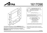
Equipment Alert
Inspect all components for shipping damages.
A concealed damage report must be filed with the
carrier (by the person receiving the goods) within 15
days of delivery.
Note:
Midmark cabinetry unit must be connected to a dedicated
circuit with disconnect rated at 20A, 115V~, 60HZ. Failure to
comply could result in an overload of the electrical circuit and/
or components. All wiring, including disconnect, and plumbing
must be installed by a licensed electrician or plumbing
contractor following applicable local, city, and national codes.
Midmark cabinetry unit contains electrical duplex outlets which
are rated at a combined 15 amps. This rating must be taken
into consideration when plugging device(s) into the available
outlets.
Note:
Refer to cabinet - mounted Procenter Delivery Unit Install
Guide (003-1256-00) for information on the delivery unit
installed in the cabinet.
TS4380 shown
midmark.com
Style G

English-2
© 2011 Midmark Corp. | 60 Vista Drive Versailles, OH 45380 USA | 1-800-643-6275 | 1-937-526-3662 |
TP201 Rev. A
Equipment Alert
Indicates a potentially hazardous situation which
could result in equipment damage if not avoided.
Caution
Indicates a potentially hazardous situation which may
result in minor or moderate injury if not avoided. It may
also be used to alert against unsafe practices
WARNING
Indicates a potentially hazardous situation which
could result in serious injury if not avoided.
Important Information and Symbols
These symbols may appear on your equipment and / or in the manuals.
Note:
Amplifies a procedure, practice or condition.
Disposal of Equipment / Consumable Goods
At the end of this products life, the unit, accessories and other consumable goods
may be contaminated from normal use. Consult local codes and ordinates for proper
disposal of this equipment and other consumables.
Pressure Limits
Humidity Limit
100 F
38 C
41 F
5 C
Temperature Limit
Type B Applied Part
Protective Earth Ground
No Stacking
Corrugated Recycle
Fragile
Keep Dry
AC (Alternating Current)
Proper Shipping Orientation
Consult User Guide
Transportation / Storage / Operating Conditions
Transportation / Storage Temperature Range: ..0°F to 140°F (-18°C to 60°C)
Relative Humidity:...............................................10% to 90% (Non-Condensing)
Atmospheric Pressure:.......................................7.2 PSI to 15.3 PSI (50 kPa to 106 kPa)
Operating Temperature Range...........................59°F to 95°F (15°C to 35°C)
~
Contact Information:
Midmark Corporation
115 G.L. Comer Road
Glasgow, Kentucky 42141
Phone: 1-800-643-6275 ext. 88015
Fax: (270)-651-1732
Intended Use
The Artizan
®
Expressions line of cabinetry is intended for use by the
professional dental practitioners as supporting products in their practice
providing adequate storage and technology integration for typical operatory
products and equipment while still retaining an aesthetic appeal. The
cabinetry should be designed to address the needs that the dental
practitioners have when working in the operatory.
midmark.com
Style G

English-3
© 2011 Midmark Corp. | 60 Vista Drive Versailles, OH 45380 USA | 1-800-643-6275 | 1-937-526-3662 |
TP201 Rev. A
Floor Layout
Note:
A full size, pre-installation floor template is available upon request:
• Treatment Station, TS3680, P/N: 003-2616-XX
• Treatment Station, TS4380, P/N: 003-2617-XX
• Treatment Station, TS4385, P/N: 003-2618-XX
• Treatment Station, TS3690, P/N: 003-2674-XX
• Treatment Station, TS4390, P/N: 003-2675-XX
Note:
Have licensed electrical and plumbing contractors position and install electrical outlet receptacles and related
plumbingusingthepre-installationtemplateorlayout.Assureoorisofsuchconstructionthattheunitwillbe
adequatelysupportedandanchored.Ifnecessarycontactalicensedcontractortoreinforcetheooring.
Template
midmark.com
Style G

English-4
© 2011 Midmark Corp. | 60 Vista Drive Versailles, OH 45380 USA | 1-800-643-6275 | 1-937-526-3662 |
TP201 Rev. A
Step 1: Remove Base Cabinet From Pallet
A) Remove Treatment Station lower from packaging.
B) Remove cabinet drawers (see Drawer Removal, Installation, and
Adjustment in this manual).
C) Remove cabinet doors and shelves. (See Door Removal, Installation,
and Adjustment in this manual)
D) Access under the cabinet through false bottom cutouts, use a 1/2”
socket to remove lag screws securing the base clips and cabinet to
shipping pallet.
E) Move cabinet into area for installation.
F) Using floor template or measurements specified on template drill holes
into floor for base clip installation. Use a 3/8” masonry drill bit for
concrete and a 9/32” wood drill bit for composite flooring.
G) Set base cabinet into place over rough-in plumbing.
Note: Be sure to save base clips to use later in the installation process to secure cabinet to
floor of the building.
Base Clip Removal / Install
Caution
Cabinet modules are significant in weight.
Lift with two people on the bottom edge of the
cabinet. Only lift the cabinet in designated locations after
drawers have been removed. Refer to illustrations for proper
lifting points.
Installation (Artizan
®
Expressions Treatment Station )
midmark.com
Style G

English-5
© 2011 Midmark Corp. | 60 Vista Drive Versailles, OH 45380 USA | 1-800-643-6275 | 1-937-526-3662 |
TP201 Rev. A
Step 2: Lower Module Installation
A) Using a level as necessary, unscrew the leg levelers using a flat head screwdriver through the
hollow leg bolt in the bottom of the cabinet (see Adjustable Camar Leg Leveler) or by hand
through the false bottom cutout until cabinet is level.
B) Use the lag screws (if floor is made of composites) and base clips that were used to secure the
cabinet to the shipping pallet and secure the cabinet to floor of the building. If the floor is
concrete, then utilize supplied floor anchors.
Note: To make installation easier and to prevent damage to area surrounding screw hole in floor, drill pilot holes. Use a 3/8”
masonry drill bit for concrete and a 9/32” wood drill bit for composite flooring.
Adjustable Camar Leg Leveler (Cabinet Height Adjustment)
A) Insert a flat head screwdriver into the hollow bolts found in the
bottom of a cabinet. Turn screwdriver clockwise to extend the leg,
and turn counterclockwise to retract the leg.
Raise
Lower
Installation (Artizan
®
Expressions Treatment Station )
midmark.com
Style G

English-6
© 2011 Midmark Corp. | 60 Vista Drive Versailles, OH 45380 USA | 1-800-643-6275 | 1-937-526-3662 |
TP201 Rev. A
Step 3: Attach Upper Cabinet
A) Unpackage Upper cabinet.
B) Remove doors and shelves. (refer to: Door Removal, Installation,
and Adjustment for more detailed instructions in this manual).
C) Lift upper into place until locating pins in Midsection structure fall
into the mounting holes on the underside of the Upper.
D) Use 6 1/4 -20 x 1.25” machine screws to fasten Upper to Midsection
from inside the Upper cabinet.
Pins in
Midsection
Midsection
Upper
Upper
Equipment Alert
Utilize the motion of installing the upper in order to not
bunch up the upholstery with the stainless valance.
Mating
Hole
Installation (Artizan
®
Expressions Treatment Station )
midmark.com
Style G

English-7
© 2011 Midmark Corp. | 60 Vista Drive Versailles, OH 45380 USA | 1-800-643-6275 | 1-937-526-3662 |
TP201 Rev. A
Step 4: Installing LED Sensor (Optional)
A) Route wire from sensor through top bracket into Midsection chase.
B) Remove front / rear panel to gain access and plug into LED power supply.
Step 5: Installing Clock/Timer
A) Remove clock/timer from packaging and remove o-ring from
clock/timer bezel.
B) Insert clock/timer through valance and reapply the o-ring on the
back side to hold clock/timer in place.
C) Plug power supply into back of clock/timer, route through
clamps, top bracket and into base cabinet.
D) Plug power supply in one of the provided outlets in base cabinet.
E) Reinstall rear panel.
Rear Panel
Sensor
Wire
Sensor
Bracket
LED
Sensor
O-Ring
Midsection
Bracket
Clock/Timer
Clamp
Midsection
Bracket
Clock/Timer
Power Supply
LED
Power
Supply
Clock/Timer
Power Supply
Wire
Clamp
Installation (Artizan
®
Expressions Treatment Station )
midmark.com
Style G

English-8
© 2011 Midmark Corp. | 60 Vista Drive Versailles, OH 45380 USA | 1-800-643-6275 | 1-937-526-3662 |
TP201 Rev. A
Step 6: Door and Drawer Installation
A) Re-install cabinet drawers (refer to: Drawer Removal, Installation,
and Adjustment in this manual) and make adjustments as needed.
B) Install shelves.
C) Re-install cabinet doors (refer to: Door Removal, Installation, and
Adjustment in this manual) and make adjustments as needed.
D) Re-install lift door. (refer to: Door Removal, Installation, and
Adjustment in this manual) and make adjustments as needed.
Note: Use rubber bumper shelf pegs for glass shelves and locking shelf pegs in the pass
through applications where shelf movement must be restricted.
Step 7: Installing Glass Midsection Shelf (Optional)
A) Loosen screws on top of clamps to allow clamps to open
enough to accept the glass shelf.
B) Place plastic shelf bumper into place on bottom support.
C) Place shelf into shelf supports.
D) Insert second plastic bumpers between top of glass surface
and top clamp.
E) Retighten shelf clamps.
Equipment Alert
Ensure glass shelf is securely fastened to
prevent it from being dislodged from clamps.
Locking
Shelf Peg
Wood
Shelf Peg
Glass
Shelf Peg
Bottom Plastic
Bumper
Glass Shelf
Top Plastic
Bumper
Tighten
Loosen
Top Plastic
Bumper
Bottom Plastic
Bumper
Installation (Artizan
®
Expressions Treatment Station )
midmark.com
Style G

English-9
© 2011 Midmark Corp. | 60 Vista Drive Versailles, OH 45380 USA | 1-800-643-6275 | 1-937-526-3662 |
TP201 Rev. A
Clock/Timer Operation
Intended Use - Clock / Timer
This product is intended to be used as a timing device to indicate the time of day, and provide a means of timing various processes used in the medical
or dental procedures.
Controls
Operation
Backup Power Mode
If power is out for less than 30 seconds:
• Clock automatically restores correct time of day.
• Timer and display operation restored as if no power loss occurred.
• No alarm if timer counts down to zero during power loss.
If power is out for more than 30 seconds:
• Timer memory loses preprogrammed times.
• Preset times return to factory setting:
(Timer 1 = 40 secs. Timer 2 = 3:00 minutes).
• If necessary, Preset times must be reset.
midmark.com
Style G

English-10
© 2011 Midmark Corp. | 60 Vista Drive Versailles, OH 45380 USA | 1-800-643-6275 | 1-937-526-3662 |
TP201 Rev. A
Timer Count-Down
Press (One Beep)
Start
Press
to increment Minutes digit to desired setting.
Hour/Min
Press
to decrement Minutes digit to desired setting.
Hour/Min
Press
to increment Seconds digit to desired setting.
Min/Sec
Press
to decrement Seconds digit to desired setting.
Min/Sec
Press (One Beep) to begin timer count-down.
Start
At the end of the count-down the display
shows and the alarm sounds 5 times:
Press
(One Beep) to stop the alarm.
Clock
Clock/Timer Operation
Setting Time of Day
Press and Hold (Two Beeps) for three seconds.
Clock
Press
to increment Hour digit to desired time.
Hour/Min
Press
to decrement Hour digit to desired time.
Hour/Min
Press
to increment Minutes digit to desired time.
Min/Sec
Press
to decrement Minutes digit to desired time.
Min/Sec
Press
(One Beep) to Save the new time of day setting.
Clock
Current Setting
New Time of Day
Note
Pressing (One Beep) cancels the count-down program and Time of Day is displayed.
Clock
00:00
Note
If the button is not depressed when the timer ends, the Clock / Timer will
begin to count-up. The time that has passed since the end of the
Clock alarm will be displayed.
Current Time of Day
00:00
midmark.com
Style G

English-11
© 2011 Midmark Corp. | 60 Vista Drive Versailles, OH 45380 USA | 1-800-643-6275 | 1-937-526-3662 |
TP201 Rev. A
Clock/Timer Operation
Timer Count-Up
Press (One Beep)
Start
Press
(One Beep) to begin timer count-up.
Start
Note
Pressing (One Beep) cancels the count-up program and Time of Day
is displayed.
Clock
00:00
Current Time of Day
00:01
Programming Preset Timer(s) for Time Setting
Press until desired preset to change is reached.
Preset
Press
or to increase desired time.
Hour/Min Min/ Sec
Press
or to decrease desired time.
Hour/Min Min/ Sec
Press and Hold
for three seconds to save new programmed time.
Preset
Preset Timer(s) Count-Down
Press until desired preset to change is reached.
Preset
Press
(One Beep) to begin timer count-down.
Start
At the end of count-down the display shows
and the alarm sounds 5 times.
Press
(One Beep) to stop the alarm.
Clock
00:00
Note
Pressing (One Beep) cancels the count-down program and Time of Day
is displayed.
Clock
Current Time of Day
Note
If the button is not depressed when the timer ends, the Clock / Timer will
begin to count-up. The time that has passed since the end of the
Clock alarm will be displayed.
Current Programmed Preset Time
New Programmed Preset Time
Current Programmed Preset Time
midmark.com
Style G

English-12
© 2011 Midmark Corp. | 60 Vista Drive Versailles, OH 45380 USA | 1-800-643-6275 | 1-937-526-3662 |
TP201 Rev. A
Note
Only Licensed Electricians following local
and applicable electrical codes should
install and connect the electrical supply power.
Midmark cannot be held responsible for
installations that do not conform to local codes.
Equipment Alert
Dedicated branch circuit rated at
120VAC, 50/60 Hz, 20 amp.
Equipment Alert
Important Notice: This unit must be
wired to a GFCI protected circuit.
TS36XX
G
G
G
G
G
WH
BK
GN/YL
BK
WH
GN
WH
BK
BK
GN/YL
GN/YL
BK
WH
WH
BK
GN
WH
WH
BK
BK
GN
WH
WH
BK
BK
BK
GN
GN
WH
WH
BK
GN
WH
BK
WH
L
N
G
N
L
G
BK
WH
GN
GN
BK
WH
BK
WH
BK
WH
GN/YL
GN/YL
Customer
Electrical
Connections
A
A
B
B
C
C
Connection
Box
D
D
E
E
LED Light
Power Assembly
F
F
Installation (Artizan
®
Expressions Treatment Station )
midmark.com
Style G

English-13
© 2011 Midmark Corp. | 60 Vista Drive Versailles, OH 45380 USA | 1-800-643-6275 | 1-937-526-3662 |
TP201 Rev. A
Note
Only Licensed Electricians following local
and applicable electrical codes should
install and connect the electrical supply power.
Midmark cannot be held responsible for
installations that do not conform to local codes.
Equipment Alert
Dedicated branch circuit rated at
120VAC, 50/60 Hz, 20 amp.
Equipment Alert
Important Notice: This unit must be
wired to a GFCI protected circuit.
TS36XX
Reversed
G
G
G
G
G
WH
BK
GN/YL
BK
WH
GN
WH
BK
BK
GN/YL
GN/YL
BK
WH
WH
BK
GN
WH
WH
BK
BK
GN
WH
WH
BK
BK
BK
GN
GN
WH
WH
BK
GN
WH
BK
WH
L
N
G
N
L
G
BK
WH
GN
GN
BK
WH
BK
WH
BK
WH
GN/YL
GN/YL
Customer
Electrical
Connections
A
A
B
B
C
C
D
D
E
E
LED Light
Power Assembly
F
F
Connection
Box
Installation (Artizan
®
Expressions Treatment Station )
midmark.com
Style G

English-14
© 2011 Midmark Corp. | 60 Vista Drive Versailles, OH 45380 USA | 1-800-643-6275 | 1-937-526-3662 |
TP201 Rev. A
G
G
G
G
WH
BK
GN/YL
BK
WH
GN
WH
BK
BK
GN/YL
GN/YL
BK
WH
WH
BK
GN
WH
WH
BK
BK
GN
WH
WH
BK
BK
BK
GN
GN
WH
WH
L
N
G
N
L
G
BK
WH
GN
GN
BK
WH
BK
WH
BK
WH
GN/YL
GN/YL
GG
G
WH
GN
WH
BK
BK
BK
WH
WH
BK
GN
WH
WH
BK
BK
GN
Note
Only Licensed Electricians following local
and applicable electrical codes should
install and connect the electrical supply power.
Midmark cannot be held responsible for
installations that do not conform to local codes.
Equipment Alert
Dedicated branch circuit rated at
120VAC, 50/60 Hz, 20 amp.
Equipment Alert
Important Notice: This unit must be
wired to a GFCI protected circuit.
TS43XX
Customer
Electrical
Connections
A
A
B
B
C
C
Connection
Box
D
D
E
E
LED Light
Power Assembly
F
F
G
G
Installation (Artizan
®
Expressions Treatment Station )
midmark.com
Style G

English-15
© 2011 Midmark Corp. | 60 Vista Drive Versailles, OH 45380 USA | 1-800-643-6275 | 1-937-526-3662 |
TP201 Rev. A
Note
Only Licensed Electricians following local
and applicable electrical codes should
install and connect the electrical supply power.
Midmark cannot be held responsible for
installations that do not conform to local codes.
Equipment Alert
Dedicated branch circuit rated at
120VAC, 50/60 Hz, 20 amp.
Equipment Alert
Important Notice: This unit must be
wired to a GCFI protected circuit.
TS43XX
Reversed
G
G
G
G
WH
BK
GN/YL
BK
WH
GN
WH
BK
BK
GN/YL
GN/YL
BK
WH
WH
BK
GN
WH
WH
BK
BK
GN
WH
WH
BK
BK
BK
GN
GN
WH
WH
L
N
G
N
L
G
BK
WH
GN
GN
BK
WH
BK
WH
BK
WH
GN/YL
GN/YL
GG
G
WH
GN
WH
BK
BK
BK
WH
WH
BK
GN
WH
WH
BK
BK
GN
Customer
Electrical
Connections
A
A
B
B
C
C
Connection
Box
D
D
E
E
LED Light
Power Assembly
F
F
G
G
Installation (Artizan
®
Expressions Treatment Station )
midmark.com
Style G

English-16
© 2011 Midmark Corp. | 60 Vista Drive Versailles, OH 45380 USA | 1-800-643-6275 | 1-937-526-3662 |
TP201 Rev. A
Drawer Installation
A) Fully extend drawer glides from the cabinet. (Optional)
B) Place the drawer on the glides.
C) Push the drawer in completely.
D) Cycle drawer a couple times to ensure that the drawer is
securely attached to the glides.
Drawer Removal
A) Open drawer completely.
B) Lift up on the drawer front until the front of the box releases from the glide.
C) Pull out on the drawer slightly.
D) Lower the drawer back down while pulling out on the drawer.
Drawer Front Adjustment and Removal
1) Remove the cover caps on the drawer side by hand.
2) Height Adjustment: Rotate in either direction to adjust the drawer front vertically.
3) Tilt Adjustment: Adjust after the drawer front is installed to ensure the drawer sides meet
square with the drawer front. (Only available on large drawer boxes.)
4) Side Adjustment: Adjusts the drawer front horizontally. Turn in either direction.
5) Tension/Removal: For large drawers, turn the screw toward the front of the drawer until the
front detaches from the box. Repeat this procedure on both sides of the drawer. For small
and medium drawer boxes, turn the screw toward the back of the drawer to remove the
front.
Drawer Removal, Installation and Adjustment
Removal
A) Extend the glide to its outermost position.
Push the release levers in and remove the
drawer member of the sides.
Full Extension Glide Removal & Installation...
Installation
A) Line up the drawer member to the cabinet
member and push the drawer into its
compartment.
A
B
C
D
GA1106
GA1107
4
5
3
2
PUSH
PULL
Cabinet Member
Drawer Member
GA1024
midmark.com
Style G

English-17
© 2011 Midmark Corp. | 60 Vista Drive Versailles, OH 45380 USA | 1-800-643-6275 | 1-937-526-3662 |
TP201 Rev. A
Hinge 1 & 2 Adjustments
Use a phillips head screw driver for the following steps...
A) Screw A adjusts the door in direction A seen in the
Adjustment Direction Guide
B) Screw B adjusts the door in direction B. Equal
adjustment must be made to all hinges on the door for it
to move the desired distance.
C) Screw C adjusts the door in the C direction. Make
adjustments to top and bottom hinge as necessary.
Note: Use a level to ensure the door is level and plumb. Preferred gaps are
approximately 1/8” between doors and 1/16” between accents and doors.
180° Hinge Adjustments
D) Loosen screw D and adjust door gap
and angle using a level. Tighten screw D
when positioned correctly,
180° Hinge
Hinge 1 & 2 Removal
E) Press button at point E at the back of
the hinge and pull away from cabinet.
Door Removal, Installation, and Adjustment
Hinge 1
Hinge 1, 2, & 3 Installation
F) Hook the hinge to the mounting block at
point F
G) Latch at point G by pressing the hinge
against the hinge block.
Hinge 2
Hinge 3
Soft Close
Switch
E
D
C
B
A
G
F
A
B
C
E
GA1019
GA1020
GA1021
A
C
B
E
C
B
A
GA1185
GA1041
midmark.com
Style G

English-18
© 2011 Midmark Corp. | 60 Vista Drive Versailles, OH 45380 USA | 1-800-643-6275 | 1-937-526-3662 |
TP201 Rev. A
Aventos HL Door Installation, Adjustment, and Removal
Aventos HL Door Installation
A) Fully extend the arm from the cabinet.
B) Hook the bottom of the mounting block located on the
door to the bottom of the arm and then tip the top of the
door towards the cabinet to latch the door to the arms.
Important
Refer to the provided image for neutral tension adjustment.
Aventos HL Stabilizer Rod Installation and
Removal
A) Slide the stabilizer rod cover caps onto the rod.
B) Insert the stabilizer rod adapters being careful
to line up the tabs.
C) Attach the rod assembly to each arm assembly
and tighten the locking screw.
D) Slide the stabilizer rod cover caps over the
locking screws.
Note: To remove the stabilizer rod undo these steps in reverse
order.
Important
For correct operation of the lifting mechanism, the stabilizer rod
must be installed.
Aventos HL Door Removal
A) Open door completely.
B) Support the door with one hand and push down on the door
front release tab at the end of the arm assemblies. Do this
for both arms.
C) Tilt the top of the door away from the cabinet and lift up to
free the door from the arms.
GA1109 GA1109
GA1110
midmark.com
Style G

English-19
© 2011 Midmark Corp. | 60 Vista Drive Versailles, OH 45380 USA | 1-800-643-6275 | 1-937-526-3662 |
TP201 Rev. A
Aventos HL Door Installation, Adjustment, and Removal
WARNING
Risk of injury from spring loaded arm
• Do not push the arm assembly down or leave in the down position
without the door attached.
Aventos HL Tension Adjustment
1) Remove the cover caps by pulling out on them.
2) Remove servo if applicable. See “Servo Drive Installation and Removal” in this
manual.
3) To adjust the lift mechanisms tension use a #2 phillips head driver. Close the door
halfway as shown below and adjust until the door balances in that position.
4) Re-install the cover caps.
GA1111
GA1113
1
2
3
GA1112
1
2
3
Aventos HL Front Adjustment
midmark.com
Style G

English-20
© 2011 Midmark Corp. | 60 Vista Drive Versailles, OH 45380 USA | 1-800-643-6275 | 1-937-526-3662 |
TP201 Rev. A
Aventos HS Door Removal
A) Open door completely.
B) Support the door with one hand and push down on the tab
with a flat blade screw driver to release the clip mechanism
on the arm assemblies. Do this for both arms.
C) Tilt the top of the door away from the cabinet and lift up to
free the door from the arms.
Aventos HS Door Installation, Adjustment, and Removal
Important
• Refer to the provided image for neutral tension adjustment.
• The amount of tension can be seen on the scale below the
adjustment screw. The tension should be the same in both
left and right lifting mechanisms.
GA1119
GA1115
Aventos HS Stabilizer Rod Installation and
Removal
A) Slide the stabilizer rod cover caps onto the rod.
B) Insert the stabilizer rod adapters being careful
to line up the tabs.
C) Attach the rod assembly to each arm assembly
and tighten the locking screw.
D) Slide the stabilizer rod cover caps over the
locking screws.
Note: To remove the stabilizer rod undo these steps in reverse
order.
GA1114
GA1114
WARNING
Risk of injury from spring loaded arm
• Do not push the arm assembly down or leave in the down position
without the door attached.
Important
For correct operation of the lifting mechanism, the stabilizer rod
must be installed.
Aventos HS Door Installation
A) Fully extend the arm from the cabinet.
B) Hook the bottom of the mounting block located on the
door to the bottom of the arm and then tip the top of the
door towards the cabinet to latch the door to the arms.
midmark.com
Style G
/