Page is loading ...

Pool Pilot
®
Digital
Salt Chlorine Generator
By
Swimming Pool and Spa Purification System
Model # 75003
Owners Manual
(For Indoor or Outdoor Use)
IMPORTANT.
Read This Manual Before Installing & Operating
This manual covers the installation of the Digital Chlorine Generator
with any of the following Cell/Manifold assemblies (sold separately);
94105, 94107, 94113, 941-15C
This manual also covers the installation, connection and programming of the
optional #75001 Pool Chemistry Controller for the Pool Pilot Digital Total Control,
and the #75004, 75005, 75006, or 75007 pH Acid Feed Pump and Tank Kit.
Pool Owner - Save this manual for reference.
Installer - Leave this manual with pool owner.

IMPORTANT SAFETY INSTRUCTIONS
ii
When installing and using this electrical
equipment, basic safety precautions should
always be followed, including the following:
READ AND FOLLOW
ALL INSTRUCTIONS
DANGER – RISK OF ELECTRICAL
SHOCK - Disconnect all AC power when
installing or servicing this system.
A bonding lug has been provided on the outside
of the Control Unit. This lug permits the
connection of a No. 8 AWG (8.4mm
2
) solid
copper-bonding conductor. Make this
connection between the Control Unit and all
other electrical equipment and exposed metal
within 5 feet (1.5m) of the Control Unit. All
field-installed metal components such as rails,
ladders, drains, etc. within 10 feet of the pool,
spa or hot tub must be bonded to the equipment
grounding bus with copper conductors not
smaller than No. 8 AWG (8.4mm
2
).
WARNING – RISK OF ELECTRICAL
SHOCK - Control units configured to 115 Vac
must be installed at least 10 feet (3m) from the
pool or spa wall. Control units configured to 230
Vac must be installed at least 5 feet (1.5m) from
the pool or spa wall.
WARNING – RISK OF CHILD DROWNING
OR INJURY - Children should never use this
equipment, or a pool, spa or hot tub unless they
are closely supervised at all times.
The AutoPilot chlorinator is equipped with an
electronic flow switch that automatically turns
the unit off in the event of a “low water flow”
situation. Do not tamper in any way with this
safety feature.
A disconnect device incorporated in the fixed
wiring must be included in the supply circuit
(such as a time clock, relay, or circuit breaker).
The proper residual chlorine level and water
chemistry must be maintained.
The addition of certain pool maintenance
chemicals can reduce the effectiveness of
chlorine.
WARNING - The Control Unit must be
mounted at least 1 foot (300mm) off the ground
to allow for air circulation around it, and
permanently installed over concrete.
The AutoPilot chlorinator must be installed and
operated as specified. Failure to do so will void
the AutoPilot warranty.
The SC-36, SC-48 and SC-60 SuperCells are
designed for residential use only. Use in any
other application will void the warranty. (The
CC-15 cell may be used in commercial or
residential applications.)
SAVE THESE
INSTRUCTIONS

UNIT NUMBERS AND CONTACT INFORMATION
iii
Please record the following information prior to installation:
Installer: .....................................................
.
Date of Installation: ...................................
.
Control Unit
Model Type: ..............................................
.
Control Unit
Serial Number: ...........................................
.
SuperCell
Model Type: ..............................................
.
SuperCell
Serial Number: ...........................................
.
Pool Volume in Gallons: ...........................
.
(Pool Volume in Liters:) ............................
.
Tri-Sensor
Serial Number: ...........................................
.
Thank you for purchasing an AutoPilot Salt Chlorination System. You will enjoy the benefits of ownership
for years to come. Please take a moment to read this manual before proceeding with the installation.
Questions?
Refer to www.AutoPilot.com
for the latest manual revisions, additional information and
helpful service.
You can also reach our factory direct customer assistance
by calling 800.786.7751 or 727.832.5642,
by email at [email protected]
,
or by FAX at 727.824.0847
Pool Pilot
®
Digital
Manufactured by
AquaCal AutoPilot Inc.
2737 24
th
Street North
St Petersburg • Florida 33713 • U.S.A.

TABLE OF CONTENTS
iv
IMPORTANT SAFETY INSTRUCTIONS ..................................................................................................... ii
UNIT NUMBERS / AUTOPILOT CONTACT INFO .................................................................................... iii
TABLE OF CONTENTS ........................................................................................................................... iv - vi
SYSTEM OVERVIEW .................................................................................................................................... 1
CHLORINE GENERATION .................................................................................................................................................................. 1
PH CONTROL M ODE ........................................................................................................................................................................ 2
TOTAL CONTROL MODE .................................................................................................................................................................. 2
T
OTAL CONTROL PROTECTION ................................................................................................................................................. 2
DEFINING ORP (ACTIVE CHLORINE) OPERATION ............................................................................................................... 2
D
EFINING PH OPERATIO N .................................................................................................................................................. 2
CONTROL UNIT FEATURES ................................................................................................................................. 3
PATENTED TEMPERATURE COMPENSA TION ..................................................................................................................................... 3
PATENTED AUTOM ATIC-FLOW BYPASS MANIFOLD ASSEMBLY ....................................................................................................... 3
SPECIFICATIONS ........................................................................................................................................... 4
FOR #75003 POO L PILOT DIGITAL CONTROL UNIT
AC
INPUT POWER ............................................................................................................................................................................ 4
C
HLORINE OUTPUT .......................................................................................................................................................................... 4
M
ANIFOLD FLOW REQUIREMENTS ................................................................................................................................................... 4
PUMP/AUXILIARY RE LAY INPUT/OUTPUT ........................................................................................................................................ 4
AGENCY APPROVALS ....................................................................................................................................................................... 4
FOR #75001 POO L CHEMISTRY CONTROLLER UNIT
PH ACID FEED PUMP AND TANK AC INPUT POWER ......................................................................................................................... 4
Low Voltage Input Power ...............................................................................................................................................................4
Flow Cell ......................................................................................................................................................................................... 4
PREPARING THE POOL WATER ................................................................................................................. 5
CALCULATING POOL VOLU ME ......................................................................................................................................................... 5
TYPE OF SALT .................................................................................................................................................................................. 5
H
OW TO ADD SALT OR REMOVE SALT ............................................................................................................................................. 5
SALT LEVEL ..................................................................................................................................................................................... 5
S
ALT ADDITION CHAR T .................................................................................................................................................................. 6
BASIC WATER CHEMISTRY .............................................................................................................................................................. 7
SATURATION INDEX (SI) .................................................................................................................................................................. 8
INSTALLATION ............................................................................................................................................. 9
BEFORE INSTALLING THE #75003 POOL PILOT DIGITAL SYS TEM ........................................................................................................ 9
W
HAT IS INCLUDED .......................................................................................................................................................................... 9
W
HAT IS NOT INCLUDED .................................................................................................................................................................. 9
P
LUMBING REQUIREMENTS ............................................................................................................................................................ 10
E
LECTRICAL REQUIR EMENTS ......................................................................................................................................................... 10
INSTALLATION STEPS ..................................................................................................................................................................... 10
PLUMBING THE MANIFOLD ASSEMBLY ............................................................................................................ 11
MOUNTING THE #75003 DIGITAL CONTROL UNIT ........................................................................................... 12
E
LECTRICAL CONNECTIONS ............................................................................................................................. 13
GROUNDING AND BONDING ............................................................................................................................. 13
H
IGH VOLTAGE WIRING .................................................................................................................................. 13
CONVERTING FROM 230 VA C TO 115VAC ................................................................................................................................... 13
C
ONNECTING POWER TO THE POOL PILOT ..................................................................................................................................... 14
C
ONNECTING POOL PILO T TO AN EXTERNAL TIMER OR CONTROLLER .......................................................................................... 14
C
ONNECTING POOL PILOT TO ONE-SPEED PUMP OR ACID PUMP ................................................................................................... 14
C
ONNECTING POOL PILOT TO TWO-SPEED PUMP ........................................................................................................................... 14

TABLE OF CONTENTS
v
LOW VOLTAGE WIRING .................................................................................................................................... 15
CONNECTING THE SUPERCELL CABLE ........................................................................................................................................... 15
CONNECTING THE TRI-SENSOR CABLE .......................................................................................................................................... 15
INSTALLATION – POOL CHEMISTRY CONTROLLER AND PH CONTROL SYSTEM ..................... 16
BEFORE INSTALLING THE #75001 POOL PILOT POOL CHEMISTRY CONTROLLER SYSTEM ............................... 17
WHAT IS INCLUDED ....................................................................................................................................................................... 17
W
HAT IS NOT INCLUDED ................................................................................................................................................................ 17
MOUNTING THE POOL CHEMISTRY CONTROLLER UNIT ................................................................ 18
POOL CHEMISTRY CONTROLLER SENSORS AND INTERFACE CABLE ......................................... 19
CONNECTING THE ORP AND P H CONNECTORS .............................................................................................................................. 19
C
ONNECTING THE INTERFACE CABLE ............................................................................................................................................ 19
P
H INSTALLATION ................................................................................................................. ..................... 20
CONNECTING THE PH FEED PUMP .................................................................................................................................................. 20
INTO THE DIGITAL CONTROL UNIT ............................................................................................................................................ 20
I
NTO THE #75008 AUXILIARY RELAY KIT .................................................................................................................................. 20
POOL CHEMISTRY CONTROLLER FLOW CELL PLUMBING ............................................................. 21
pH CONTROL PLUMBING .......................................................................................................................... 22
CONNECTING THE #75003 DIGITAL TO ANY OTHER ORP CONTROLLER ..................................... 23
INSTALLING THE O PTIONAL #110-ORP RELAY KIT ................................................................................................................... 23
CONNECTING THE #75003 DIGITAL TO AN ELECTRONIC CONTROLLER ..................................... 24
MENU OVERVIEW ...................................................................................................................................... 25
PROGRAMMING AND OPERATION ......................................................................................................... 27
CONTROL PANEL FEATURES AND FUNCTIONS .................................................................................................. 26
CONTROL OPTIONS AND SYSTEM START UP ...................................................................................................... 27
PURIFIER MODE - QUICK PROGRAM MING ...................................................................................................................................... 27
PH CONTROL MODE - QUICK PROGRAM MING ................................................................................................................................ 28
TOTAL CONTROL (TC) MOD E - QUICK PROGRAMMING ................................................................................................................. 28
OPERATION OF BUTTONS ................................................................................................................................. 29
ADJUSTING THE PURIF IER OUTPUT % ............................................................................................................................................ 29
BOOST OR SUPERBOOST ................................................................................................................................................................ 29
M
ENU BUTTON .............................................................................................................................................................................. 29
S
ELECT BUTTON ............................................................................................................................................................................ 29
P
UMP BUTTON ............................................................................................................................................................................... 30
TEST POOL PILOT PROGRAM ............................................................................................................................ 31
VIEW SETUP PROGRAM .................................................................................................................................... 31
SELECT LANGUAGE PROGRAM ......................................................................................................................... 32
S
ELECT UNITS PROGRAM ................................................................................................................................. 32
SELECT TEMPERATURE PROGRAM ................................................................................................................... 32
S
ELECT 12/24 HOUR CLOCK PROGRAM ............................................................................................................ 32
SET TIME OF DAY PROGRAM ............................................................................................................................ 32
PROGRAMMI NG PUMP OPERATING TIMES ........................................................................................................ 32
A
CTIVATING FORCE REVERSE.......................................................................................................................... 33
P
ROGRAMMI NG REVERSE TIME ....................................................................................................................... 33
E
NABLE / DISABLE REMOTE ............................................................................................................................ 33
R
EPLACE CELL (RESET AMPERE - HOUR COUNTER) ......................................................................................... 33
S
ET PRIME PROTECT ........................................................................................................................................ 33

TABLE OF CONTENTS
vi
SALT CALIBRATION .......................................................................................................................................... 34
ADJUSTING TEMPERATURE DISPLAY ................................................................................................................. 34
P
ROGRAMMI NG POOL VOLUME ....................................................................................................................... 34
PROGRAMMI NG CELL TYPE ............................................................................................................................. 34
PROGRAMMI NG CELL POWER .......................................................................................................................... 34
PROGRAMMI NG SET RELAY 1 FUNCTION (PUMP CONTROL) ............................................................................ 34
P
ROGRAMMI NG SELECT REMOTE (ELECTRONIC CONTROLLER INTERFACE) .................................................... 35
P
ROGRAMMI NG SYSTEM MODE ....................................................................................................................... 35
PH CONTROL AND TOTAL CONTROL MENUS ................................................................................................... 35
BOOST ACID .................................................................................................................................................................................. 35
PRIME ACID PUMP ......................................................................................................................................................................... 35
R
ESET ACID ME TER ........................................................................................................................................................................ 35
ENABLE / DISABLE ACID ................................................................................................................................................................. 35
TOTAL CONTROL MENUS ................................................................................................................................. 36
SET PH OVERFEED .......................................................................................................................................................................... 36
SET PH MIN ..................................................................................................................................................................................... 36
SET PH MAX .................................................................................................................................................................................... 36
CALIBRATING PH ............................................................................................................................................................................ 36
ENABLE/DISABLE ORP ................................................................................................................................................................... 36
SET ORP OVERFEED ....................................................................................................................................................................... 36
ELECTRONIC CONTROLLER OPERATION ........................................................................................................... 37
ADJUSTING AND SUPERCH LORINATING THE POOL P ILOT THROUGH TH E ELECTRONIC CONTROLLER CONTROL PANE L.................. 37
PROGRAMMING THE P OOL PILOT DIGITAL FOR AN ELECTRONIC CONTROLLER ............................................................................. 37
ELECTRONIC CONTROLLER DI SPLAYS “CHECK POOL PILOT” ................................................................................................... 37
SYSTEM MAINTENANCE .......................................................................................................................... 38
WINTERIZING ................................................................................................................................................................................. 38
FREEZE PROTECTION PROGRAM .................................................................................................................................................... 38
S
PRING START-UP.......................................................................................................................................................................... 38
FUSE LOCATIONS AND RATINGS .................................................................................................................................................... 39
TRI-SENSOR ASSEMBLY ................................................................................................................................... 40
REMOVING/INS PECTING/CLEANING THE TRI-SENSOR ..................................................................................................................... 40
T
ESTING THE FLOW SWITCH, CLEANING THE FILTER SCREEN, AND CLEANING THE BYPAS S VALVE ............................................ 41
SUPERCELL ...................................................................................................................................................... 41
REMOVAL OF TH E SUPERCELL ....................................................................................................................................................... 41
V
ISUAL INSPECTION OF THE SUPERCELL ....................................................................................................................................... 42
M
ANUAL CLEANING OF THE SUPERCELL ....................................................................................................................................... 42
I
NSTALLATION OF THE SUPER CELL ................................................................................................................................................ 42
POOL CHEMISTRY CONTROL MAINTENANCE AND CLEANING ..................................................... 43
HELPFUL HINTS ............................................................................................................................................................................. 43
R
EMOVAL ...................................................................................................................................................................................... 43
C
LEANING ...................................................................................................................................................................................... 43
T
ESTING THE FLOW CELL .............................................................................................................................................................. 43
TROUBLESHOOTING GUIDE ............................................................................................................. 44 - 49
STANDARD DISPLAYS ............................................................................................................................................................. 44 - 47
OTHER CONDITIONS ....................................................................................................................................................................... 47
TOTAL CONTROL A ND PH DISPLAYS ....................................................................................................................................... 48 - 49

SYSTEM OVERVIEW
1
System Overview
Although the Pool Pilot is easy to use, it is important to read through the manual before attempting to operate the unit. The Pool
Pilot Digital, #75003, is a salt chlorination system for pool or spa purification, which is designed to operate in the following
configurations:
• Purifier – standard mode, manually adjusted purifier output. See pg. 27 for system operation and programming.
• Purifier and pH Control – optional mode – standard purifier mode operating in conjunction with the optional pH Acid
Feed Pump and Tank System (#75004 , #75005, #75006, #75007 ), which is manually programmed for daily pH control.
This mode will require #75008 Auxiliary Relay Kit when using the Digital “Set Relay 1” to control the main circulation
pump. See pg. 28 for system operation and programming.
• Total Control – optional mode - utilizing the optional #75001 Po o l Chemistry Controller for automatic daily adjustments
of purifier and pH, based upon user programmed settings. See pg. 28 for system operation and programming.
The Pool Pilot has a digital interface that allows the unit to be operated through a Jandy® Aqualink RS (versions I and K only),
Polaris® EOS, or Pentair IntelliTouch® electronic remote panel located in your home (if so equipped), or through an external
ORP controller. The Pool Pilot Digital can also be programmed to control the main circulation pump operating times or be
controller by an external timer/switch/relay.
Chlorine Generation (Manual purifier control)
The system requires a low concentration of dissolved salt (sod iu m chloride) in the pool water. This level is normally below the
taste threshold. The Pool Pilot auto matically converts the salt into free chlorine, which keeps your pool sanitized an d algae free.
The chlorine reverts back to a salt after treating the water. Since the salt is constantly recycled, there is min imal loss during a
swimming season. However, salt can be lost due to filter backwash, rain water overflow, leaks, or bather splashing/carryout, but
not through evaporation.
The Pool Pilot Contr ol Uni t is desi gned to handle the pu ri fi c a t i on need s of resi de nt i a l and com m e rci al swimming pools. The cel l
must be properly sized according to the chlorine requirements. The amount of chlorine required for proper sanitization will vary
based on the pool size and various factors such as water temperature, bather load, exposure to direct sunlight, special water
features, and pump runtime, particularly in commercial applicatio n s.
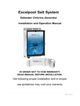
Electronic
Controller
System
Dotted lines are
optional
connection
schematics and
components.
pH Acid
Feed System
#75004,
#75005,
#75006,
#75007.
#75008
Auxiliar
y
Relay Kit
Dotted lines are
optional connections,
equipment, schematics,
and components
#75001
Pool
Chemistry
Control
Circuit
Breaker
Timer
AUTOPILOT
SYSTEMS
INC
#75003
Digital
Control

SYSTEM OVERVIEW
2
pH Control Mode (Manual purifier and pH control)
Note: Requires option # 75004, 75005, 75006, or 75007 pH Acid Feed Pump and Tank System must be installed with the #75003
Digital Controller for this mode to function. Option # 75008 Auxiliary Relay Kit will be necessary if the Digital is used to control
the main circulation pump.
This mode adds to the Purifier mode by using an Acid feed pump that is user programmed for manual feed of diluted muriatic
acid. The Acid Feed Pump and Tank System come with AutoPilot and Stenner factory components. If the Stenner factory
components are used for the installation, follow their installation instructions. Otherwise, follow the instructions in this manual.
Total Control Mode - Pool Chemistry Controller (Automated purifier and pH control)
Note: Option #75001 Pool Chemistry Controller and the pH Control System must both be installed with the #75003 Digital
Controller for this mode to function.
These options activate the Total Contro l mode in which the purifier (ORP – defined below) and pH levels are monitored (using
sensors) and controlled automatically, to main tain proper levels. The system automatically enters the Total Con trol configuration
if it is able to communicate with the Pool Chemistry Controller. The system will display "Error purify off, Error acid off, Check
OpEC" if it is not able to communicate with th e Pool Chemistry Controller. OpEC is the acronym for “O
RP pH Electronic
C
ontroller” and is the electronic control logic of the Pool Chemistry Controller. Under normal operating mode, the Total Control
display cycles between the “ORP” screen, the “pH” screen, and the “Salt level” screen.
Total Control Protection
The Total Control system does not generate chlorine or dispense acid if:
• A one-speed or two speed pump is not running,
• Flow (at the Manifold Tri-sensor or Flow Cell flow switch) is not detected,
• Salt is below 2000 ppm,
• Communications with the #75001 Pool Chemistry Con troller is lost,
• A sensor error is detected,
• An overfeed condition is detected (if set to detect pH or ORP overfeed),
• An extended period of high pH cond ition is detected.
Also:
• The Total Control system does not dispense acid until after flow has been detected a minimum of th ree (3) minutes
after activation.
• The Total Control system does not generate chlorine or dispense acid one (1) minute prior to the Pump Program “Off”
time, when programmed for a One speed pump.
ORP (Oxidation Reduction Potential - measured in millivolts, mV)
ORP is a measurement of the amount of active oxidizer (chlorine) in the water. This system controls ORP by generating chlorine
when the ORP measurement falls below a user programmable set point, which shou ld correspond with the desired free chlorine
level. A one-minute timer prevents the chlorine generation circuit from cycling on/off unless an error condition ex ists.
The first line of the ORP screen displays the measured ORP, followed by the ORP set point in parenthesi s (as show n b el ow ). The
ORP screen contains the text “On” only if chlorine is being generated. The ORP display range is 200 to 900mV.
The second line of the ORP screen indicates if the ORP is high or low, relative to th e set point. If the measured ORP is equal to
the set point, a block █ with no text is displayed. If the measurement falls below the set point, the ▼ and Low ar e displayed and
chlorine is generated. If the measurement exceeds the set point, the ▲ and High are displayed and no chlorine is generated.
pH
The system controls pH by dispensing diluted mixture of water and muriatic acid (4:1 ratio recommended) when the pH rises
above a user programmable set po int, wh ich should correspond with the desired pH level. To avoid overdo sing , the system
dispenses acid in low incremen ts based on the difference between the set point and the meas ured pH.
The first line of the pH screen displays the measured pH, followed by the pH set point in parenthesis (as shown below). The pH
screen contains the text “On” only if acid is being dispensed. The pH display range is 4.00 to 9.90.
The second line of the pH screen indicates if the pH is high or low, relative to the set point. If the measured pH is equal to the set
point, a block █ with no text is displayed. If the measurement falls below the set point, the ▼ and Low are displayed and no acid
is fed. If the measurement exceeds the set point, the ▲ and High are displayed and acid is fed until set point is reached.
pH 4.00(7.50)
█▼▼▼▼▼▼▼ Low
pH 7.50(7.50)
█
pH 9.90(7.50) On
High ▲▲▲▲▲▲▲▲█
ORP 200(650)On.
█▼▼▼▼▼▼▼ Low
ORP 650(650)
█
ORP 900(650)
High ▲▲▲▲▲▲▲▲█

SYSTEM OVERVIEW
3
Control Unit Features
The control unit has the fo llowing features:
• Patented temperature compensation for chlorine output
• Programmable Microprocessor Control
• Multi-language digital display – (English, Sp an ish, French & German)
• Digitally controlled power to the Sup erCell
• Tri-sensor Circuitry to monitor water flow, water temperature, and salt level
(and salt addition amounts to maintain 3000 ppm (3.0 g/l))
• Internal Relay for controlling an external pump or acid feed er
• On-board Diagnostic and Test programs
• Lithium battery (CR-2025) back up for clock and program settings
• ORP dry contact interface for connection to an external ORP controller.
• Electronic controller interface for Jandy®
(Versions I, K, and newer), Polaris® EOS,
or Pentair IntelliTouch® controllers.
Patented Temperature Compensation
The Tri-Sensor Assembly’s temperature sensor works in conjunction with the purifier % output to automatically adjust the
chlorine output based upon changes in the water temperature between the range of 55°F – 95°F (13°C - 35°C). As temperatures
fall lower than 75°F (24°C), the unit will activate a high purifier % lock out and may not allow purifier adjustments up to 100%.
This prevents the unit from overdriving the cell under cold temperatures, which can cause premature cell wear. At 55°F (13°C) o r
colder, the unit will adjust to a fixed 1% output to prev en t the over chlorination and prematur e cell failure during cooler
temperatures. At 95°F (35°C) or warmer, the unit will adjust up to 100% of the normal purifier % setting to prevent under
chlorination during warmer temperatures.
The Temperature Compensation feature is not needed and is therefor e automatically disabled when the Pool Pilo t Digital (model
#75003) is installed as a part of the Digital TC Total Control System (in conjunction with AutoPilot’s Pool Chemistry Controller -
# 75001)
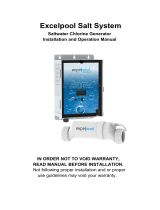
Patented Automatic-Flow Bypass Manifold Assembly
The manifold is connected into the pool plumbing. Water from the
pool is circulated though the manifold by the circulation/filter pump.
The manifold’s four key components are the strainer screen,
Tri-Sensor, Su perC el l , a nd by pass fl o w val v e.
The strainer screen prevents debris in the water from entering the
Tri-Sensor or SuperCell and requires periodic inspection and cleaning.
The Tri-Sensor provides data (from electronic sensors) to the Control
Unit for monitoring water flow, water temperature, and salt lev el
through the cell. The Con trol Unit will use this data to determine if
the conditions are safe for the SuperCell to operate.
The SuperCell receives power from the Control Unit and converts
the salt water to chlorine.
The Bypass Flow Valve allows water flow rate to be optimized
through the Sup e rCell. The slo wer water flow through the SuperCell
results in a more efficient “Super-Chlorination effect” in the cell that
results in better overall sanitization results.
Tri-Sensor
SuperCell
Strainer Screen
Bypass Flow Valve
CHECK
SYSTEM
BOOST MEN U SELECT PUMP

SPECIFICATIONS
4
Specifications
#75003 Pool Pilot Digital Control unit
Input Power
230 Vac 1.5 amps (Normal input configuration shipped from the factory)
115 Vac 3 amps (Optional input configuration – jumper wire to convert included)
Dry Contact 5 mA typical Non-factory ORP input circuit (110Vac output require a Relay Kit – PN# 110-ORP)
Chlorine Output
SuperCell Type Maximum Chlorine Output (# 75003 Control unit set on Cell Power 3)
SC-36 1.28 lbs/day (0.58 kg/day)
SC-48 1.56 lbs/day (0.71 kg/day)
SC-60 1.92 lbs/day (0.88 kg/day)
CC-15 2.50 lbs/day (1 .14 kg/day) – Com mercial Cell
Manifold Flow Requirements
Minimum Flow Rate 20 gallons per minute (gpm) (76 liters/minute (L/m))
Maximum Flow Rate 100 gallons per minute (gpm) (379 liters/minute (L/m))
Maximum Pressure 85 psi (as tested by NSF)
Pump/Auxiliary Relay Output
Voltage Input Amps / HP max
115 Vac 30 amps / 1 HP
230 Vac 30 amps / 2.5 HP
Agency Approvals
• ETL tested to conform to the following UL specifications:
o UL1081 - Standard for Safety for Swimming Pool Pumps, Filters and Chlorinators
o UL 1563 - Standard for Safety for Electric Spas, Equipment Assemblies, and Associated Equipment.
• CAN/CSA-E335-1 - Safety of Household and Similar Electrical Appliances
#75001 Pool Pilot Pool Chemistry Control unit
pH Acid Feed Pump and Tank AC Input Power
#75004 120 Vac 1.7 amps
#75005 220 Vac 0.9 amps
#75006 230 Vac 0.9 amps
#75007 250 Vac 0.9 amps
#75008 Auxiliary Relay Kit 1 15 / 230 Vac Relay 30 amps max
Low Voltage Input Power
PCC Comm uni cati on Factory Low Volt a ge Int erface Cable provided with #75 00 1
#75008 pH Auxiliary Relay Kit (Optional) Dedicated Factory Low Voltage Terminal
Flow Cell
Flow Sensor Fail – Safe status
Maximum working pressure 50 psi

PREPARING THE POOL WATER
5
Calculating Pool Volume (needed to determine proper balance chemical additions)
(
)
2
end shallow ofdepth end deep ofdepth
Depth Average
+
=
Pool Shape Gallons (pool size measured in feet) Liters (pool size measured in meters)
Rectangular Length x Width x Average Depth x 7.5 Len gt h x Wi dth x Average D ept h x 1 00 0
Round Diameter x Di ameter x Average Depth x 5.9 Diameter x Diam et er x Average Depth x 785
Oval Length x Width x Average Dept h x 5. 9 Length x Width x Average Dept h x 7 85
Your calculated pool volume is ____________. Enter this number for reference on the information section , pg. iii.
Type of Salt
It is important to use Sodium Chloride (NaCl) salt that is greater than 99% pure. Common types of salt include granular food
grade, water softener pe llets, or so lar salt flak es. These are usually available in 25 lb to 80 lb bags at a local po o l or building
supply store. Water softener and solar salt will have a slower dissolve rate than food grade salt. Rock salt and Granular Salt with
Iodine or Rust Preventatives should no t
be used as they contain high levels of impurities that will cau se staining.
Note: Granular salt with anti-caking additives such as YPS (Yellow Prussiate of Soda) or Sodium Ferrocyanide can be used but
may cause a localized tint to the water or yellow staining on the pool finish if not mixed and dissolved immediately.
How to Add or Remove Salt
The filter pump should be turned on and run continuously for 24 hours after salt is add ed to th e pool to allow for proper
dissolving and circulation throu ghout the pool. The filter pump should be run continually for up to 24 hou rs. The salt should be
added directly to the pool and over the bottom main drain if so equipped. If there is no main drain, a vacuum head can be used to
circulate the salt. Vacuum the salt, brush it around to agitate, or brush into the main drain (if applicable) to speed up the
dissolving process.
Caution:
Do not use a pool cleaner or vacuum head with wheels as they can leave track marks on newly plastered pools.
Do not allow Granular salt to pile up in one location without brushing as staining may occur.
If the salt level in the pool beco mes undesirably high, the on ly way to remove excess salt is to partially drain the pool and refill
with fresh water.
Salt Level
Your Pool Pilot requires that the size of your pool be entered into the microprocessor so that it can automatically measure the
amount of salt in your pool and indicate how many pounds (kgs) to add when the salt level falls low. To program your pool size,
see “Set Pool Volume” on pg. 34. To calculate the number of gallons (liters) of water in your pool, see Calculating Pool Volume
above. The salt chart on the following page can also be used to calculate how much salt, in pounds (kgs) should be added to reach
the recommend e d level of 3000 ppm (3.0 g/l).
The ideal salt range is 2500 – 3500 PPM (parts per million) (2.5 – 3.5 g/l). However, the Pool Pilot can operate with salt levels in
excess of 35,000 PPM (35.0 g/l), if so desired. High salt levels above 6000 PPM are not normally recommended as this may
cause corrosion to metallic objects such as light fixtures, ladders, handrails, heaters, and pumps. Low salt levels below 2400ppm
will reduce the efficiency of the Pool Pilot and result in low chlorin e production. Extremely low salt levels below 1900 pp m will
activate the low salt safety cut-off and h alt chlorin e production until salt is replenished to proper salt levels.
The salt is constantly recycled during normal operation. The loss of salt during a swimmin g season should be minimal. Filter
backwashing, draining due to rain water overflow, sp lashing and ba thing suit drag out, and leaks (excessive salt loss in a short
span of time) are typical ways the salt is lost. Salt does not evaporate from the pool when the water evaporate s.

PREPARING THE POOL WATER
6
Salt Addition Chart
The following salt chart is included for reference only. Once your Pool Pilot Digital is properly programmed to the pool water
volume, it will automatically indicate how much salt is needed. To use this chart:
1. Find your current salt level (ppm or g/l) in the left column. (This can be obtained from your Pool Pilot display or by
testing your water.)
2. Find your pool/spa volume in the second row (Gallons or Liters).
3. Find the amount of salt needed to bring your po ol to the ideal level by finding the in tersectio n of the row and column.
For volumes other than what is shown, use combinations of various columns.
For example, for an 11,000 gallon (41,64 6 liter) poo l with a salt level of 500 pp m (5 mg/l), the column valu e for 1000 gallons
(4,000 liters) (21 pou nds (9 kg)) is added to the co lumn value for 10,000 gallons (38,000 liters) (209 pounds (95 kg)) wh ich gives
a total of 230 pounds (104 kg) of salt needed to bring your pool salt level up to the ideal level of 3000 ppm (3.0 g/l).
Pounds (kilograms) of Salt needed to attain 3000 ppm (3.0 g/l)
Pool/Spa Volume in Gallons (Liters)
1,000 2,000 5,000 10,000 15,000 20,000 25,000 30,000 35,000 40,000
Current
salt level
ppm
(g/l)
(4,000) (8,000) (18,000) (38,000) (56,000) (76,000) (94,000) (114,000) (132,000) (152,000)
25 50 125 250 376 501 626 751 876 1,002
0
(11) (23) (57) (114) (170) (227) (284) (341) (398) (454)
23 46 115 230 344 459 574 689 803 918
250
(0.25)
(10) (21) (52) (104) (156) (208) (260) (312) (364) (416)
21 42 104 209 313 417 522 626 730 835
500
(0.50)
(9) (19) (47) (95) (142) (189) (237) (284) (331) (379)
19 38 94 188 282 376 470 563 657 751
750
(0.75)
(9) (17) (43) (85) (128) (170) (213) (256) (298) (341)
17 33 83 167 250 334 417 501 584 668
1,000
(1.0)
(8) (15) (38) (76) (114) (151) (189) (227) (265) (303)
15 29 73 146 219 292 365 438 511 584
1,250
(1.25)
(7) (13) (33) (66) (99) (133) (166) (199) (232) (265)
13 25 63 125 188 250 313 376 438 501
1,500
(1.5)
(6) (11) (28) (57) (85) (114) (142) (170) (199) (227)
10 21 52 104 157 209 261 313 365 417
1,750
(1.75)
(5) (9 ) (24) (47) (71) (95) (118) (142) (166) (189)
8 17 42 83 125 167 209 250 292 334
2,000
(2.0)
(4) (8) (19) (38) (57) (76) (95) (114) (133) (151)
6 13 31 63 94 125 157 188 219 250
2,250
(2.25)
(3) (6 ) (14) (28) (43) (57) (71) (85) (99) (114)
4 8 21 42 63 83 104 125 146 167
2,500
(2.5)
(2) (4) (9) (19) (28) (38) (47) (57) (66) (76)
3,000
(3.0)
Ideal
3,500
(3.5)
OK for Pool Pilot Operation – (This is typically the maximum salt level desired by most pool
owners/operators since most people can taste salt levels above this.)
Greater
than
3,500
OK for Pool Pilot Operation but greater than 6000 ppm can cause corrosion to metallic
objects- (If lower salt level is desired, partially drain and refill with fresh water.)

PREPARING THE POOL WATER
7
Basic Water Chemistry
Your Pool Pilot Digital is designed to produce chlorine on a daily basis. To monitor your system’s efficiency, the water
chemistry ranges and schedule of periodic checks outlined below should be followed.
CHEMICAL IDEAL RANGE IDEAL TEST
SCHEDULE
EFFECT OF LOW/HIGH LEVELS CORRECTIVE ACTIONS
Free Chlorine
1.0 To 3.0 ppm Weekly Low free chlorine:
Not enough residual
chlorine to safely sanitize pool water.
High free chlorine: Corrosive to metallic
fixtures in pool water. Can bleach
swimwear and hair.
Low free chlorine: Check for
combined chlorine level and shock as
necessary. Increase purifier output to
maintain a 1-3 ppm residual reading.
High free chlorine: Decrease purifier
output. Let chlorine dissipate
normally until 1-3 ppm is achieved.
In extreme cases, pool water can be
diluted with fresh water or a chlorine
neutralizer added. (Diluting will
reduce salt and CYA. Check and
adjust as needed.)
pH
7.2 To 7.8 Weekly Low pH: (acidic) Equipment corrosion,
eye/skin irritation, plaster etching, rapid
chlorine consumption
High pH:
(basic) Scale formation,
cloudy water, eye/skin irritation, poor
chlorine effectiveness
Low pH
: Add sodium carbonate or
soda ash
High pH:
Add muriatic acid or
sodium bisulfate.
Total
Alkalinity
80 To 120 ppm Monthly Low TA: Eye irritation, pH “bounce”,
stained/etched plaster and metal
corrosion.
High TA:
Constant acid demand,
difficulty in maintaining pH, and
contributes to scale formation or cloudy
water conditions.
Low TA:
Add sodium bicarbonate.
High TA:
Add muriatic acid often, a
little at a time (may take a week or
more to lower the TA). Aerate by
pointing return jets toward the
surface.
Salt
2500 To 3500 ppm Monthly Low Salt: Below 2,400 ppm causes
premature cell failure and reduces
chlorine production
High Salt:
Above 6,000 ppm can cause
corrosion of metallic fixtures and will
taste salty. Note: AutoPilot can safely
operate with salt levels up to 35,000.
Low Salt:
Add salt according to
digital display on Pool Pilot unit or
salt chart.
High Salt:
If undesirably high,
partially drain and refill the pool with
fresh water. (Diluting will reduce
CYA. Check and adjust as needed.)
Calcium
Hardness
200 To 400 ppm Monthly Low CH: Etching of plaster, equipment
corrosion
High CH:
Scale formation, cloudy
water. Rapid buildup of scale may
exceed the system’s self-cleaning
capability and require manual cleaning
of the SuperCell.
Low CH:
Add calcium chloride
flakes.
High CH:
Partially drain and refill
pool with fresh water to dilute.
(Diluting will reduce salt and CYA.
Check and adjust as needed.)
Cyanuric Acid
(CYA or
Stabilizer)
60
30
To
To
80
50
ppm
ppm
Monthly Low CYA:
destruc tion of chlori ne by
the UV rays from the sun.
High CYA: Requires more chlorine to
maintain proper sanitizer levels.
Note: CYA not needed for indoor or
bromine pools.
CYA can be reduced to 30 – 50 ppm for
Pool Pilot Digital TC/ORP or colder
climate regions.
Low CYA:
Add cyanuric acid
(1 lb/5000 gallons increases CYA 25
ppm)
High CYA:
Partially drain and refill
pool with fresh water to dilute.
(Diluting will reduce salt. Check and
adjust as needed.)
! WARNING
Excessively high chlorine levels can cause premature cell failure and corrosion
damage to pool fixtures and equipment.
! WARNING
Always follow the instructions on the manufacturer’s label whenever adding
chemicals to your pool.

PREPARING THE POOL WATER
8
Saturation Index (SI)
The Saturation Index is a formula used to predict th e calcium carbonate saturation of water, that is, wheth er your water will
precipitate, dissolve, or be in equilibrium with calcium carbonate. Your water is properly balanced if the SI is 0 ± 0.3. If your SI
is greater than 0.3, scaling and staining will occur. If your SI is less than -0.3, then the water is corrosive to metallic fixtures and
aggressive to plaster surfaces and vinyl liners. A high or low SI can cause premature damage to the cell, equipment or pool
finish. As a general rule, higher concentrations of calcium, total dissolved solids, pH, and alkalinity all promote a greater
tendency for scale. Scaling potential also increases with increasing temperature.
Use the chart below to determine your overall water balance. Test your water for pH, water temperature, Calcium Hardness,
Total Alkalinity and Salt Level and use the equ ivalent Factors (TF, CF, AF, Constant) from the chart below to determine your
Saturation Index. Adjust your chemicals to maintain balanced water.
pH + TF + CF + AF – SC = SI
Temperature TF
Calcium
Hardness
CF
Total
Alkalinity
AF
Salt Level SC
60
o
F 15.6
o
C 0.4 150 ppm 1.8 75 ppm 1.9 0 – 1000 ppm 12.1
66
o
F 18.9
o
C 0.5 200 ppm 1.9 100 ppm 2. 0 1001 - 2000 pp m 12.2
76
o
F 24.4
o
C 0.6 250 ppm 2.0 125 ppm 2. 1 2001 - 3000 pp m 12.3
84
o
F 28.9
o
C 0.7 300 ppm 2.1 150 ppm 2. 2 3001 - 4000 pp m 12.4
94
o
F 34.4
o
C 0.8 400 ppm 2.2 200 ppm 2. 3 4001 - 5000 pp m 12.5
103
o
F 39.4
o
C 0.9 600 ppm 2.4 250 ppm 2. 4 5001 - 6000 pp m 12.6
-.3 -.2 -.1 0 .1 .2 .3
Corrosive to
metals, etches
plaster
finis hes, and
irritates skin
OK
Scaling,
staining, and
cloudy water
conditions
Examples
Water test results #1:
Total Alkalinity = 125 ppm => AF = 2.1
Calcium Hardness = 400 ppm => CF = 2.2
pH = 7.4 => pH = 7.4
Water Temperature = 84 F => TF = 0.7
Salt Level = 3000 ppm => SC = 12.4
7.4 + 0.7 + 2.2 + 2.1 – 12.4 = 0 (Water is perfect l y balance d )
Water test results #2:
Total Alkalinity = 200 ppm => AF = 2.3
Calcium Hardness = 600 ppm => CF = 2.4
pH = 7.8 => pH = 7.8
Water Temperature = 84 F => TF = 0.7
Salt Level = 3000 ppm => SC = 12.4
7.8 + 0.7 + 2.4 + 2.3 – 12.4 = 0.8 (Water is scale forming)

INSTALLATION
9
Before Installing the # 75003 Pool Pilot Digital System
• Determine that everything needed for installatio n is on hand
• Determine where the Manifold Assembly will be plumbed
• Find a suitable mounting location for the Control Unit within proper cord len gth to the manifold
• Plan cord runs for SuperCell Cable and Tri-Sensor Cable
• For optional TC or pH control systems, plan for flow cell water feed tubes and acid feed tube and electrical connections
• Plan wire runs and wiring conn ections for source power and optional connections if any;
o Determine where input power for the Pool Pilot will orig inate
directly from a circuit breaker
from an external Timer or
from an electronic controller
o Determine whether the input voltage for the Poo l Pilot is 230Vac (factory configured) o r 115Vac
o Determine whether the Pool Pilo t will b e used to control a single sp eed pump or a dual speed pump
o Determine whether the Pool Pilot will b e controlled by an ORP controller (or TCC Option)
o Determine whether the Pool Pilot will be contro lled by an Electronic Controller system.
What is included?
Although the manifold assembly may be sold separately, both a manifold and a Pool Pilot Digital Contro l unit are required for a
complete installation and start-up. The stan dard cell/manifold assembly is available with the following cells: SC-36, SC-48, SC-
60 (residential cells), or the CC-15 (commercial cell). Before attempting the installation, check that the fo llowing items have
been included with th e Po ol Pilot Pool Pilot Digital Control un it:
DIGITAL CONTROLLER
Quantity Item Description
1 # 75003 Pool Pilot Dig ital Control Unit
AC jumper for 11 5 Vac configuration
1 Tri-Sensor Cable
1 SuperCell Cable
1 Mounting Template
4 Plastic Anchors
4 Mounting Screws
*2 68mm x 2” metric adapters (#19059)
* European Systems only
What is not included
Some of the additional equ ipment that may be needed to complete the in stallation:
For any installation
• Appropriate gauge electrical wire
• ½”liquidtite (non-metallic flex) conduit
• ½” conduit connector for service to th e Pool Pilot
• Drill
• ¼” masonry drill bit
For installations using option al equipment
• Appropriate gauge electrical wire
• ½” liquidtite (non-metallic flex) conduit
• ½” conduit connector for filter pump
• Cable for connection for ORP interface (PN # 315-AC)
• 4-Conductor cable for connection to Electronic Controller option
Pool Pilot is to be wired to the same location as the main filter pump
so that it only activated when the pump is energized.
Digital Time clock is used to control the main pump
or pump is also running off the breaker
CHECK
SYSTE
M
BOOST MENU SELECT P UMP
MOUNTING
TEMPLATE
Drill (4) ¼
cations.
Drill o
Sean Assam

INSTALLATION
10
Plumbing Requirements
The Manifold Assembly is 2” Schedule 40 and is typically p lumbed into the pool return line and, if applicable, after the heater
and spa return diverter valve.
Electrical Requirements
Power must be shut off at the circuit breaker before performing any wiring. All local and NEC electrical codes should be
followed.
The Pool Pilot Digital has been factory configured for 230Vac operation. If it needs to be reconfigured for 115Vac operation,
then see Converting fro m 230 Vac to 115Vac on pg. 13.
Installation Steps
Details on each step of the installation process are presented on the following pages:
1. Plumbing the Manifol d Asse mbly (pg. 11)
2. Mounting the Pool Pilot Digital (pg. 12)
3. Electrical connections (pgs. 1 3 - 15 )
a. Grounding and bo nd ing
b. High voltage wiring
i. Pool Pilot Digital to an external timer or controller
ii. Pool Pilot Digital relay for a One-speed pump or pH acid feed pump (optional)
iii. Pool Pilot Digital relay for a Two speed pump output (optio n al)
iv. Pool Pilot Digital relay for acid feeder (optional)
c. Low voltage wiring
i. SuperCell cable
ii. Tri-Sensor cable
4. #75001 Pool C hemistry Cont rol l e r Co n fi g uration – optio nal (p gs. 16 - 23)
5. Electronic Control Configuration – optional (pg. 24)
6. Menu Overview (pg. 25)
7. System Startup and programming (pgs. 26 - 37)

INSTALLATION
11
Plumbing the Manifold Assembly
Step 1: Select the location for installing the manifold:
The manifold is designed for a flow rate of 20 to 100 gpm (76 to 379 L/m).
• It is recommended that the manifold be installed prior to installation of th e control unit. The Control Unit will need
to be installed close enough to the Manifold Assembly so that the Tri-Sensor and SuperCell Cables (12’ long) will
have enough slack so that the cables can be serviced easily.
• The manifold/cell should be installed in a vertical orientation as illu strated in the picture below. This orientation
prevents hazard ous gas buildup in the system if the flow switch should fail to detect insufficient flow.
• The direction of the water flow through the manifold must be as indicated for the syst em to work properly.
• For a Pool/Spa combination, the
manifold must be located as the
last component in the POOL
RETURN LINE to avoid over-
sanitization of the SPA.
For flow rates within the normal range:
• The manifold can be directly
plumbed into the system as shown
in the diagram to the right.
• If the flow rate for the system is
less than 20 gpm (76 L/m),
a larger pump must be installed.
Note: Ensure that flow rates for a two-
speed pump can provide sufficient flow at low speed.
For flow rates greater than 100 gpm (379 L/m):
• A 5 lb spring bypass check valve must be
plumbed in parallel with th e manifo ld as
shown in the d iagram to the right.
Step 2: Install the cell into the manifold with the cell cable terminals at the bottom of the manifold as illustrated in the picture.
Tighten the unions by hand
for a watertight seal. The manifold will accept the SC-36, SC-48, SC-60 residential cells, or the
CC-15 commercial cell.
! WARNING
If the cell is improperly installed upside down, water from rain or other sources may enter
the cable contacts and result in failure of the SuperCell and void your warranty.
5 lb bypass valve
Main Flow
To Pool Return

INSTALLATION
12
Mounting the #75003 Pool Pilot Digital Control Unit
Caution: All electrical connections should be made by a licensed electrician or certified electrical contractor.
Your Pool Pilot Digital is suitable for indoor or outdoor moun ting. If it is connected to 230 Vac, it must be installed at least 5’
(1.5m) horizontal distance from the pool or spa wall (or more if local codes require). If it is connected to 115 Vac, it must be
installed at least 10’ (3m) horizontal distance from the pool or spa wall.
The Pool Pilot Digital is designed to mount vertically on a flat surface with the wiring inputs facing downward. The enclosure is
designed to allow heat to dissipate from inside the box. It is important not to block the top or bottom of the box. Do NOT
mount
the unit inside a panel or a tightly enclosed area without proper ventilation.
The cover of the Pool Pilot Digital is removed from the sides by four thumbscrews so it is advisable to leave adequate space on
the sides for hand access to the thumbscrews.
When selecting a location for installing the Pool Pilot Digital, please note that the Tri-Sensor and SuperCell cables are 12’ (3.6 m)
long.
Warning: Verify that the selected Pool Pilot Digital location is close enough to the Manifold Assembly so that the Tri-
Sensor and SuperCell Cables will have enough slack so that the cables can be easily handled for service or maintenance.
Read the following section completely before proceeding (damage to wires and connectors may occur):
1. Level and tape the mounting template to the selected mounting location. Mark the wall for the 4
mounting h ol es.
2. Plastic anchors and screws have been provided for concrete or stucco walls. Drill and install the plastic
anchors and/or screws. Leave a ¼” gap from the wall when tightening the screws.
3. Loosen but do not remove the 4 thumbscrews on the sides of the Control Unit.
(2 thumbscrews on each side)
4. Carefully slide off the outer housing cover. Disconnect the 3 plugs that
connect to the display board (indicated by ) that is mounted inside
the cover. (The display circuit board does not need to be removed from
the cover.)
5. Safely set the cover aside.
6. Hang the Pool Pilot Digital on the four mountin g screws.
Using a long shaft slotted screwdriver, tighten the screws through
the black plastic access holes (indicated by ).
7. For access to the electrical terminal strip, remove the four screws
and lift off the inner metal protective cover.
8. Route the (2) ribbon connectors from the display circuit board side through
the slotted access hole, then remove the (1) power plug on the po wer circ ui t
board side and route through the slotted access hole.
9. Safely set the metal protective cover aside.
10. See Electrical Connections on pgs. 13 – 15 fo r te rminal connections.
11. Reverse steps 3 - 8 to re-install the metal and outer covers. Make sure to route and connect the ribbon
connectors and power plug through the metal protective cover properly, then replace the outer housi ng
cover after first connecting the 3 plugs (that were disconnected in Step 4).
CHECK
SYSTEM
BOOST MENU SELECT P UMP

INSTALLATION
13
Optional 115 Volt configuration
230 Volt factory configuration
Electrical Connections
The Pool Pilot Digital uses both high and low voltage connection s . High vo ltag e connections will be made for providing the
direct input power to it. Additional h igh voltage connections may be made to the filter pump from the Pool Pilot Digital. Low
voltage connections will be made to the Tri-Sensor and SuperCell. Additional low voltage co nnections are provided for option al
equipment such as #75008 pH feed er, #75001 Pool Chemistry Contr oller, or an ORP or electronic contro l.
! DANGER
Ensure that power is disconnected before wiring this unit.
Follow all state / local / NEC (CEC if applicable) electrical codes.
Use copper conductors only.
Grounding and Bonding
Connect a ground wire from the primary electrical input to the grounding lug located inside the box. Also ground any piece of
high voltage equipment that is connected to the Pool Pilot Digital relay.
The Pool Pilot Digital must also be connected to th e pool bonding system with an 8AWG (6AWG for Canada) wire. A lug is
provided on exterior of the unit at the bottom.
High Voltage Wiring
Converting from 230 Vac to 115Vac
The #75003 Pool Pilot Digital h a s b een configured at th e facto ry for
230Vac service. Verify that this is the desired input voltage
configuration.
If 115Vac input power is required, follow the directions below to
convert the input voltag e.
• If the cover has not been removed, review the steps in
Mounting the #750 03 Pool Pilot Digital on pg. 12 for
instructions on removing the cover and disconnecting
the cable plugs at the display board.
• Remove the single jumper wire and re-attach as shown
in the diagram.
• Locate the jumper wire prov ided in the installation kit
and attach as shown in the diagram.

INSTALLATION
14
High Voltage Wiring
Connecting Power to the Pool Pilot Digital
The Pool Pilot Digital is typically provid ed input power in one of two ways. Determine which is best for your application.
• AC input directly from a circuit breaker, time clock, or pump relay in an electronic controller:
This method is
used when the AC power to the pump and Pool Pilot will be turned on and off by an external device such as a circuit
breaker, time clock, or electronic controller.
• AC input directly from an external breaker:
This method is used only when the Pool Pilot Digital will be u s ed to
time and control the filter pump on/off cycles.
Note: Turn Power OFF and remove the short factory test wire stubs connected to the top terminals and ground lug before wiring.
You must provide the approp riate gauge LINE-IN wires for pump or non-pump applications. Check with your local codes or
NEC guidelines.
Connecting Pool Pilot Digital to an External Timer or Controller
LINE-IN:
1) Measure and cut the appropriate gauge wires and ½” non-metallic flexible conduit from the Power source to the
Pool Pilot Digital.
2) Connect ac wires to the LOAD SIDE or to the same location as the circulation pump wires (pump connected to circuit
br eak er, time clock or electronic controller ) and run through the conduit to the Po ol Pilot Digital.
3) Conn ect the ac wires into the Pool Pilot Digital to terminals #1 and #2 on the Terminal Strip.
4) Conn ect the ground wire to the ground lug to the left of the Terminal Strip.
Connecting Pool Pilot Digital to One-Speed Pump or pH Acid Feed Pump
LINE-IN:
1) Follow the LINE-IN instructions above.
2) Select wire gauge and type that meets local and national
electrical codes for powering the pump.
LINE-OUT:
1 ) Connect th e LIN E-OUT pump wires to terminals #4, #6
and the ground lu g as labeled.
Connecting Pool Pilot Digital to Two-Speed Pump
LINE-IN:
1) Fo llow th e LINE-IN instructions above.
2) Select wire gauge and type that meets local and national
electrical codes for powering the pump.
Note: The pump is always powered. A safety shut off (wall switch)
between the circuit breaker and Pool Pilot Digital is recommended
if the circuit breaker cannot be accessed quickly.
LINE-OUT:
1) Connect the LINE-OUT pump wires to terminals
#3, #4, #5, and the ground lug as labeled.
(LINE- OUT)
to Two Speed
Pump
Terminal Strip
#1
#2
#3
#4 #5
#6
GND
L1/L
L2/N
To
Circuit
Breaker
GND
LowHigh
COM
Time Clock or
Electronic
Controller Relay
(LINE IN)
from Circuit Breaker
or Electrical Panel
(LOAD OUT)
to Digital
Terminal Strip
#1
#2
#3
#4 #5
#6
Ground Wire
To Pump
(LINE-OUT) to
One-Sp eed Pump or
pH Acid Feed Pump
Terminal Strip
#1
#2
#3
#4 #5
#6
GND
L1/L
L2/N
From
Circuit
Breaker
GNDL2/NL1/L
/