Page is loading ...

AquaCal®
Operation Manual
LTM0883 REV 2a
Important
Read this document before operating / installing this product
For additional product manuals and operation / installation procedures, please visit www.AquaCal.com

Table of Contents
Section 1 - Contacting AquaCal AutoPilot, Inc.
Section 2 - Safety
Section 3 - Operation
3.1 Energizing Heat Pump 2
3.2 Display Door 2
3.3 Display Lock 2
3.4 Display Panel 2
3.4.a Buttons 3
3.4.b Indicator Lights 3
3.4.c Display 3
3.5 User Level Factory Defaults 4
3.6 Setting Operating Mode 5
3.7 Selecting Celsius or Fahrenheit 5
3.8 Setting Thermostats 5
3.9 User Lock Option (Enable) 6
3.10 User Lock Option (Disable) 7
3.11 User Lock Option (Entering Pass Code) 7
3.12 Operating Heat Pump (With an External Controller) 8
Section 4 - Maintenance
4.1 Monitoring Conditions 8
4.1.a Water Chemistry 8
4.1.b Water Flow Rates 9
4.1.c Adjusting Water Flow Using ΔT (Delta-T) 10
4.1.d Irrigation and Storm Run-Off 11
4.1.e Clearances 11
4.2 Cleaning Equipment 12
4.3 Planned Maintenance 13
4.4 Winterizing 14
Section 5 - Troubleshooting
5.1 Fault Codes 16
5.2 Issues and Resolutions 18
Section 6 - Appendix
6.1 Identifying Model Specifications 21
6.2 Initial Heating Recommendations 22
6.3 Initial Cooling Recommendations 22
6.4 Available Accessories 22
i

Page - 1
SECTION 1 - CONTACTING AQUACAL AUTOPILOT, INC.
For further assistance, please contact the installing dealer or contact AquaCal AutoPilot, Inc. for a service
partner in your area. To better assist you, please have the heat pump model and serial number available. See
"Identifying Model Specifications" on page 21.
Website www.AquaCal.com
Request Service Online www.AquaCal.com/request-heat-pump-service/
Phone (1) 727-823-5642
Hours 8-5 pm, Eastern M-F
SECTION 2 - SAFETY
lFor personal safety, and to avoid damage to equipment, follow all safety instructions displayed on the equipment
and within this manual. Repair and service of heat pump must be performed by an authorized service center.
lWarranties may be voided if the equipment has been improperly installed, maintained or serviced.
lIf service is deemed necessary, please contact the installing dealer. Or contact AquaCal®for a service partner in
your area. See "Contacting AquaCal AutoPilot, Inc." on page 1.
SAFETY SIGNALS
Throughout this document, safety signals have been placed where particular attention is
required.
WARNING - signals relate to personal safety.
CAUTION - signals promote avoiding damage to the equipment.
When installing and using your heat pump basic safety precautions must always be followed, including the
following:
WARNING - Failure to heed the following may result in injury or death.
lInstallation and repairs must be performed by a qualified technician.
lThe heat pump contains refrigerant under pressure. Repairs to the refrigerant circuit must not be attempted by
untrained and / or unqualified individuals. Service must be performed only by qualified HVAC technicians.
Recover refrigerant before opening the system.
lThe heat pump utilizes high voltage and rotating equipment. Use caution when servicing.
lElectrical installation and service should be performed by a Licensed Electrician only.
lImproper water chemistry can present a serious health hazard. To avoid possible hazards, maintain pool / spa
water per standards detailed in this document.
lProlonged immersion in water warmer than normal body temperature may cause a condition known as
Hyperthermia. The symptoms of Hyperthermia include unawareness of impending hazard, failure to perceive
heat, failure to recognize the need to exit the spa, and unconsciousness. The use of alcohol, drugs, or medication
can greatly increase the risk of fatal Hyperthermia. In addition, persons having an adverse medical history, or
pregnant women, should consult a physician before using a hot tub or spa. Children and the extreme elderly
should be supervised by a responsible adult.
lProlonged immersion in water colder than normal body temperature may cause a condition known as
Hypothermia. The symptoms of Hypothermia include shivering (although as hypothermia worsens, shivering
stops), clumsiness or lack of coordination, slurred speech or mumbling, confusion and poor decision-making,
drowsiness or low energy, lack of concern about personal welfare, progressive loss of consciousness, weak
pulse and slow or shallow breathing. In addition, persons having an adverse medical history, or pregnant
women, should consult a physician before immersing in a cold body of water. Children and the extreme elderly
should be supervised by a responsible adult.

Page - 2
CAUTION - Failure to heed the following may result in equipment damage.
lMaintain proper water chemistry in order to avoid damage to pump, filter, pool shell, etc.
lWater flow exceeding maximum flow rate requires a bypass. Damage due to excessive water flow will void
warranty.
SAVE THESE INSTRUCTIONS
SECTION 3 - OPERATION
3.1 Energizing Heat Pump
Turn power on at external fuse box or breaker disconnect.
lController performs a lamp test.
lThe display reads 888.
lController then displays as normal. See "Display" on page 3.
3.2 Display Door
The display panel is located in a door compartment on the front of the heat pump. This compartment is
designed to protect the display against harsh weather. It can also be padlocked for extra security.
lPress the bottom of the
panel to open the
display panel door.
lTo close, push the
display panel up. Then
press the bottom of the
panel in until a clicking
noise is heard.
3.3 Display Lock
The heat pump has a display lock to protect against
inadvertent setting changes. To activate display and
controls, slide finger across the controls as shown from
left to right.
lThe code UnL will briefly appear, then the set temperature
or mode will display.
lThis is different than a user-lock which requires a pass
code. See "User Lock Option (Enable)" on page 6.
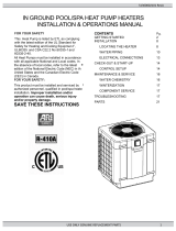
3.4 Display Panel
Display Panel
The following information outlines the operation for a standard installation.
lControl Buttons will operate differently for custom installations; such as a
heat pump connected to an external controller. See "Operating Heat Pump
(With an External Controller)" on page 8.

Page - 3
3.4.a Buttons
Buttons Description
Display Lock Sliding your finger across the buttons from left to right will
temporarily disable the display lock.
Pool / Spa Select either the pool or the spa thermostat.
Up Arrow Used to increase temperature set point and navigate
though menu options.
Down Arrow Used to decrease temperature set point and navigate
though menu options.
Mode Select heat pump's operating mode.
3.4.b Indicator Lights
Indicators Description
Pool The Heat Pump is referencing the pool thermostat.
Spa The Heat Pump is referencing the spa thermostat.
Heating
Indicates the unit is heating the water.
Please note - the compressor must be operating before this
light will illuminate.
Cooling
Indicates the unit is cooling the water.
Please note - the compressor must be operating before this
light will illuminate.
Water Temp Indicates current water temperature.
Desired Temp Indicates temperature set point is displayed. This is
displayed when "UP" or "DOWN" is selected.
3.4.c Display
Display Description
75 The heat pump is on and displaying the current water
temperature. In this example 75° F is displayed.
FLO No water flow is detected. The filter pump is off or heat
pump is not receiving correct water flow.
OFF
The heat pump has been turned off via the mode selector
button or the temperature set point has been lowered
below 45° F.
888
The control program is initializing. This displays only as
power is applied to the heat pump. The program version
number will then be displayed.

Page - 4
Display Description
CF1 Select water temperature format (in either Celsius or
Fahrenheit).
ULC Enable heat pump lockout feature.
ELC Select passcode to lock the keyboard.
LOC
This is a Service Entry Point (not intended for use by the
owner). The LOC code permits service personnel to enter a
factory passcode to access adjustable calibration and site
dependent setup parameters. Service adjustments are
available to authorized installation and service personnel,
only.
3.5 User Level Factory Defaults
Certain programming options have been preset at the factory. These options can be overwritten for site-
specific conditions.
CAUTION - Failure to heed the following may result in equipment damage.
lUnauthorized adjustments in the Installer Menu (beyond the LOC menu) may void heat pump's warranty.
CODE DESCRIPTION DEFAULT
VALUE RANGE
OFF Heat Pump is
deactivated.
HEA
Set to heat water
to point set on
thermostat.
COO
Set to cool water
to point set on
thermostat.
ACH
Set to maintain a
water temperature
set on the
thermostat.
CF1
Celsius /
Fahrenheit
Selection
10 = Celsius
1 = Fahrenheit
ELC Enter Lock Code 0 0 - 99
ULC User Lock Code 0 0 = "User Lock Disabled"
1 = "User Lock Enabled"
Table 1 - Factory Defaults

Page - 5
3.6 Setting Operating Mode
Heat
Mode
Cool
Mode
Automatic
Heat / Cool Mode
Deactivate
Heat Pump
Heating / Cooling modes only available
on select equipment. Confirm heat pump
features before setting a mode.
3.7 Selecting Celsius or Fahrenheit
Hold "UP" and
"DOWN" until
CF1 displays.
Press "UP or
"DOWN" button
to select.
"0" - Celsius
"1" - Fahrenheit
3.8 Setting Thermostats
Select "POOL" or
"SPA"
Press "UP" or
"DOWN" to the
desired
temperature.
lThe heating
indicator will
illuminate when
heating the
water.
lThe cooling
indicator will
illuminate when
cooling the
water.

Page - 6
3.9 User Lock Option (Enable)
The user-lock feature allows the heat pump display panel to be "locked". This can prevent unauthorized
temperature adjustments in commercial applications.
lDo not confuse a user-lock with the display lock. See "Display Lock" on page 2.
lIf LOC is briefly displayed, followed by a "0", the heat pump is already locked.
lIf the user-lock code has been misplaced, please contact AquaCal®Customer Service for
further assistance.
Hold "UP" and
"DOWN" until
CF1 displays.
Press "POOL /
SPA" button until
ELC is displayed.
Press "UP or
"DOWN" button to
change or add a
numerical password
Press "POOL /
SPA" button to
lock in the
password.
Press "POOL /
SPA" button until
ULC is displayed.
Press "Up" button
till "1" is
displayed to
enable.

Page - 7
3.10 User Lock Option (Disable)
Use "UP" button
to enter existing
password.
Press "Pool / Spa"
button to unlock.
Hold "UP" and
"DOWN" buttons
until CF1 is
displayed.
Press "POOL /
SPA" button until
ULC is displayed
Press "DOWN"
button until "0" is
displayed.
3.11 User Lock Option (Entering Pass Code)
If LOC is briefly displayed when attempting to change a heat pump's settings followed by a "0", the heat
pump is in a user-lock mode. A numerical passcode is required to proceed.
Press "UP" or
"DOWN" arrow
to enter user lock
code.
Press "POOL /
SPA" button to
unlock.
NOTE -
lAfter three seconds of inactivity, the heat pump's display lock will activate. See "Display
Lock" on page 2.
lIf the user-lock code has been misplaced, please contact AquaCal®Customer Service for
further assistance.

Page - 8
3.12 Operating Heat Pump (With an External Controller)
Controller with an internal thermostat control
Activating Heat Pump
1. Set the desired temperature at the external controller.
2. Use the external controller to select either the "Pool" or "Spa" to heat.
Deactivating Heat Pump
lSet the external controller to "OFF".
Please note - If equipped, the heat pump's cooling function will be disabled when using
this type of controller.
If the cooling function is needed, the heat pump must be temporarily re-programed for
local control. Check with controller installer if heat pump needs to be re-programmed.
Controller with 2 positions - ("Pool"and "Spa" - no internal thermostat control)
Activating Heat Pump
1. Set the desired temperatures on the heat pump thermostats. See "Setting Thermostats" on page 5.
2. Use the external controller to select either the "Pool"or "Spa" to heat.
lRapid movement between thermostats without a "rest"between each change can cause a missed signal
by the heat pump.
Deactivating Heat Pump
lGo to the heat pump and set the mode to "OFF". See "Setting Operating Mode" on page 5.
Please note - If equipped, the heat pump's cooling function will be disabled when using
this type of controller.
If the cooling function is needed, the heat pump must be temporarily re-programed for
local control. Check with controller installer if heat pump needs to be re-programmed.
Controller with 3 positions - ("High", "Low", and "Off" - no internal thermostat control):
Activating Heat Pump
1. Set the desired temperatures on the heat pump thermostats. See "Setting Thermostats" on page 5.
2. Use the external controller to select either "High"or "Low" to heat.
lWhen changing between thermostats, select "Off" first. Then select desired thermostat.
lRapid movement between thermostats without a "rest"between each change can cause a missed signal
by the heat pump.
Deactivating Heat Pump
lSet the external controller to "OFF".
SECTION 4 - MAINTENANCE
4.1 Monitoring Conditions
4.1.a Water Chemistry
Check water chemistry regularly and maintain within recommended levels. Standards for commercial
applications vary in different areas. Follow all local applicable codes.
CAUTION - Failure to heed the following may result in equipment damage.
lDo not allow water to flow through heat pump when refinishing or acid washing a pool. Either use an installed
bypass to route water away from heat pump or deactivate filter pump.
lTo avoid damage to equipment, monitor and maintain chemistry within recommended levels.

Page - 9
CHEMISTRY LEVEL CHART
(RESIDENTIAL)
CHEMICAL POOLS SPAS
Chlorine 1.0 – 3.0 ppm 3.0 – 5.0 ppm
Bromine 2.0 – 6.0 ppm 2.0 – 6.0 ppm
Cyanuric
Acid 30 - 50 ppm 30 - 50 ppm
pH 7.4 – 7.6 ppm 7.4 – 7.6 ppm
Total
Alkalinity 80 – 120 ppm 80 – 120 ppm
Calcium
Hardness
200 – 400
ppm 150 – 250 ppm
Total
Dissolved
Solids•
0 – 1,500 ppm 1,500 ppm above start-up total dissolved solids in
spas
•Salt from a chlorine generator is not included in Total Dissolved Solids.
4.1.b Water Flow Rates
Maintain water flow rates as indicated. Please note, these specifications relate to the heat pump only. Code-
specified whole system turnover rates must be satisfied.
CAUTION - Failure to heed the following may result in equipment damage.
lWater flow exceeding maximum flow rate may damage heat exchanger; such damage will not be covered under
the equipment warranty
MODEL HEAT EXCHANGER TYPE FLOW RATES
MINIMUM MAXIMUM
SQ120R Titanium ThermoLink®30 GPM 70 GPM
SQ125 Titanium ThermoLink®30 GPM 70 GPM
SQ145 Titanium ThermoLink®30 GPM 70 GPM
SQ166R Titanium ThermoLink®30 GPM 70 GPM
SQ225 Titanium ThermoLink®30 GPM 70 GPM
T035 Titanium Tube-in-Tube 20 GPM 45 GPM
T055 Titanium Tube-in-Tube 20 GPM 45 GPM
T075 Titanium Tube-in-Tube 20 GPM 45 GPM
T090 Titanium ThermoLink®30 GPM 70 GPM
T115 Titanium ThermoLink®30 GPM 70 GPM
T135 Titanium ThermoLink®30 GPM 70 GPM

Page - 10
If water flow through the heat pump is reduced, performance will suffer and internal safety devices may
deactivate the heat pump with error codes HP and HP5, or (if equipped) an LP and LP5.
lOperate water filtration devices per manufacturer's specifications. Dirty filters can cause reduced water flow to the
heat pump. An increase of 7-10 psi higher than the clean filter pressure typically reduces flow rates. This requires
the filter to be cleaned or back-washed
lKeep baskets free of debris. Similar to a dirty filter, large volumes of debris in the pump and skimmer baskets can
reduce water flow.
lCheck for improper valve settings. A partially closed valve after the filter, or a full-open bypass around the heat
pump, will cause insufficient water flow through the heat pump.
lThe maximum static (or operating pressure) is 50 pounds-per-square-inch (PSI). These specifications relate to the
heat pump only. Code-specified whole system turnover rates must be satisfied.
4.1.c Adjusting Water Flow Using ΔT (Delta-T)
The Delta-T is the temperature difference between the water temperatures entering and leaving the heat
pump. The equipment can be fine-tuned for maximum performance by balancing water flow rates to
maintain an ideal ∆T.
lInstalled Temperature / Pressure probes and ports are required to perform the following procedures.
lThis adjustment procedure is to be completed with the unit in HEA mode only;ACH and COO discharge
temperatures are not shown.
PLEASE NOTE -
Temperature / Pressure ports are required for all commercial applications.
They are strongly recommended (but not required) for residential installations.
Temperature / Pressure Port
(Shown with Probe)
1. Adjust heat pump thermostat to its lowest setting while in
HEA mode.
2. Deactivate the water filtration pump.
3. Adjust valves to a halfway open position leading to the
heat pump.
4. Adjust valves to a fully open position leading away from
the heat pump.
5. Activate the pool water filtration pump.
6. Slowly turn the thermostat up until the heat pump
activates.
lAfter a four-minute delay, the heat pump
compressor will start.
7. With the heat pump running, confirm water filtration
pump is operating properly with adequate flow and no
short cycling. If needed, clean filters leading to the heat
pump.
8. Wait for water and refrigerant pressure to stabilize (approximately 5 minutes).
9. Adjust valves in the following order:
A. Adjust valve leading away from the heat pump to correct temperatures measured with a temperature
pressure probe.
B. Allow pressure to stabilize . Then check temperature again. Re-adjust valve leading away from the
heat pump as needed.
10. Mark valves at these positions for future reference.
Temperature differences are based on pool temperatures of 72° (+ or – 3° F). For water
temperatures outside this range, contact AquaCal®Technical Support.

Page - 11
MODEL TEMPERATURE
SQ120R 3° to 7° F
SQ125 3° to 7° F
SQ145 3° to 7° F
SQ166R 3° to 8° F
SQ225 4° to 9° F
T035 1° to 4° F
T055 2° to 5° F
T075 3° to 7° F
T090 3° to 6° F
T115 3° to 7° F
T135 4° to 8° F
Table 2 - Temperature Chart
4.1.d Irrigation and Storm Run-Off
lIrrigation water may damage heat pump components. Have irrigation water directed away from the heat pump.
lThe heat pump will withstand normal rainfall. Do not allow a roof slope to direct rainwater onto the heat pump.
Have a gutter installed on the roof edge to direct this water away from the heat pump. Or install the heat pump in
another location.
4.1.e Clearances
lProper air circulation is required for the heat pump to operate efficiently. Avoid placing objects near or on top of
the heat pump. This includes shrubbery and lawn furniture. These objects will also hinder maintenance access.
lAvoid storing chemical containers near the heat pump. The chemicals can cause equipment damage.
Overhead Clearance

Page - 12
HeatWave SuperQuiet®and TropiCal®(Top View)
4.2 Cleaning Equipment
Cleaning and polishing your heat pump regularly can protect its appearance and longevity. More frequent
servicing may be required for heat pumps located in sandy or coastal areas where sand and salt spray can
become detrimental factors to equipment.
WARNING - Failure to heed the following may result in injury or death.
lPossible electric shock hazard - Deactivate power to all electrical devices on the pad when washing heat pump.
Do not restore electrical power until equipment is completely dry.
CAUTION - Failure to heed the following may result in equipment damage.
lDo not use a pressure cleaner to wash heat pump. Damage to heat pump components may result. If using a hose-
end spray nozzle adjust spray pattern to low strength only.
lDo not spray water directly into the interior of the heat pump; damage to components may result.
lDo not use chemicals on the display panel.

Page - 13
Cleaning
1. Wash outside cabinet using a low-pressure water hose. A high-pressure water stream will cause damage to the
aluminum fins of the heat pump. This damage is not covered under product warranty.
2. While the heat pump is still wet, use an approved cleaning agent to clean the exterior of the heat pump. Do not
use chemicals on the display panel.
3. Use a detergent-dampened cloth to wipe the heat pump's exterior cabinet.
4. Flush all exterior with fresh water using a low-pressure water hose.
5. Dry the exterior cabinet using a soft cloth being careful not to damage evaporator fins.
APPROVED CLEANING AGENTS•
Fantastic®
Formula 409®
Cascade®
All Power Plain Detergent (3% Solution)
Table 3 - Cleaning Agents
Polishing
1. Polish the heat pump’s cabinet panels using an approved polishing agent and following the manufacturer’s
instructions. Do not use chemicals on the display panel.
2. Rinse the heat pump panels with fresh water, wipe, and buff panels using a dry soft cloth.
3. Allow heat pump interior and surrounding equipment to "air-dry" for several hours prior to restoring electrical
power.
APPROVED POLISHING AGENTS•
Simoniz®Wax
Glo-Coat®
Armor All®Protectant
Table 4 - Polishing Agents
•The trademarks used in approved cleaning and polishing agents are property of their owners and are not
related to AquaCal®.
4.3 Planned Maintenance
An annual inspection and maintenance program is strongly recommended starting no longer than one year
after installation of the heat pump. In coastal areas a bi-annual inspection is recommended. See
recommended inspection checklist.
AquaCal®can perform this service in limited areas. Contact Customer Support for more information.
WARNING - Failure to heed the following may result in injury or death.
lAnnual inspection and service must be performed by a qualified heat pump specialist in order to prevent
physical injury or damage to equipment.

Page - 14
RECOMMENDED INSPECTION CHECKLIST:
lCheck Air Temperature Change through Evaporator
lCheck and Clean Condensate Drains
lCheck Capacitor Value
lCheck Compressor Amperage Draw
lCheck Electrical Connections
lCheck Flow / Pressure Switch
lCheck Operating Controls and Temperature Sensors
lCheck Water Chemistry
lCheck Proper Voltage to Unit
lCheck Refrigerant Levels
lCheck Relay Contacts
lCheck Water Flow
lCheck filter pump Amperage Draw
lCheck Water Temperature Change through Heat Exchanger
lClean Evaporator's Coil
lClean Heat Pump's Cabinet
4.4 Winterizing
WARNING - Failure to heed the following may result in injury or death.
lDeactivate all electrical power to heat pump before performing hard freeze procedures.
CAUTION - Failure to heed the following may result in equipment damage.
lFailure to winterize heat pump may result in serious equipment damage. Freeze damage is not covered under the
heat pump warranty.
lWhile the plumbing connections are in the winterized condition (not fully tightened), it is imperative the pool
and spa water not be circulated through the heat pump. Loss of water through loose plumbing connections may
result in damage to circulation pump, pool and spa structures, and other equipment.
Light Freeze Conditions
There are two freeze conditions requiring heat pump attention. A light freeze is when the ambient air
temperature falls below 32 degrees Fahrenheit for less than 8 hours. Typically during light freeze conditions
circulating (moving) water will not freeze. Override time clocks and allow filtration system to run
continuously during light freeze conditions.
Hard Freeze Conditions
A hard freeze is when the ambient air temperature falls below 32 degrees Fahrenheit for more than 8 hours.
In areas where this condition is prevalent and sustained, the heat pump MUST be winterized for hard freeze
conditions. Follow the correct procedure depending on the type of heat exchanger found in the heat pump.
Identify Exchanger:
1. Deactivate all electrical power to heat pump.
2. Deactivate filter pump.
3. Remove front access panel.
4. Identify heat pump exchanger from illustrations in this section. Then follow procedure for that heat pump's
exchanger.

Page - 15
Titanium ThermoLink®Exchanger (with Internal Drain)
Internal
Drain
1. Disconnect the plumbing to the heat pump at connection unions (removal is counter-
clockwise).
2. Remove internal drain plug.
3. Allow water to drain completely from the heat pump. Expect to see a lot of water drain out
at first, and then a small amount to continue to drain out over a long period.
4. After heat pump is fully drained, re-connect internal drain plug and reinstall front access
panel.
5. Partially reconnect plumbing connection unions.
6. Winterizing is complete.
7. When ready to use heat pump again, hand-tighten connection unions. Reconnect electrical
power, and set the operating mode on the heat pump. Activate filter pump.
Titanium ThermoLink®Exchanger (with no Drain)
No Drain
1. Reinstall front access panel.
2. Disconnect the plumbing to the heat pump at connection unions (removal is counter-
clockwise).
3. Allow water to drain completely from the heat pump. Expect to see a lot of water drain out
at first, and then a small amount to continue to drain out over a long period.
4. After heat pump is fully drained, reinstall front access panel.
5. Partially reconnect plumbing connection unions.
6. Winterizing is complete.
7. When ready to use heat pump again, hand-tighten connection unions. Reconnect electrical
power, and set the operating mode on the heat pump. Activate filter pump.
Titanium Tube-in-Tube Exchanger
Titanium
Tube-in-
Tube
1. Disconnect the plumbing to the heat pump at connection unions (removal is counter-
clockwise).
2. Allow water to drain completely from the heat pump. Expect to see a lot of water drain out
at first, and then a small amount to continue to drain out over a long period.
3. Place an air hose into the pool inlet of the heat pump; wrap a clean rag around the hose to
form a temporary seal.
4. Push all water from the water circuit using compressed air no stronger than 50 psig. The
residual water should be forced out of the pool outlet. Allow compressed air to blow into
the heat pump inlet for at least 15-20 seconds after the water stops coming out.
5. Repeat process on the outlet side of the heat pump.
6. Partially reconnect plumbing connection unions.
7. Winterizing is complete.
8. When ready to use heat pump again, hand-tighten connection unions. Reconnect electrical power, and set the
operating mode on the heat pump. Activate filter pump.

Page - 16
SECTION 5 - TROUBLESHOOTING
5.1 Fault Codes
A fault code indicates a specific issue or condition that will require action before the equipment can resume
operating.
Please perform the following troubleshooting.
If the issue reoccurs, please contact the installing dealer. Or contact AquaCal®for a service
partner in your area. See "Contacting AquaCal AutoPilot, Inc." on page 1.
WARNING - Failure to heed the following may result in injury or death.
lRepairs must not be attempted by untrained or unqualified individuals.
lThe heat pump contains refrigerant under high pressure. Repairs to the refrigerant circuit must not be attempted
by untrained or unqualified individuals. Service must be performed only by qualified HVAC technicians.
Recover refrigerant before opening the system.
CAUTION - Failure to heed the following may result in equipment damage.
lService by unauthorized personnel will void the heat pump warranty.
FLO Indicator
ISSUE
Low or no water detected.
RESOLUTION
1. Confirm the filter pump is on.
2. If a multiple-speed filter pump is being used, run at a higher speed to determine if the error persists. Do not
exceed maximum flow rate for your model.
3. Confirm water is not being diverted away from the heat pump.
lSee "Water Flow Rates" on page 9.
lSee "Adjusting Water Flow Using ΔT (Delta-T)" on page 10.
CEr Indicator
ISSUE
This can indicate a loose or damaged communication cable.
RESOLUTION
A qualified technician should check the cable from control board to display assembly for a loose connection
or visible damage.
CSE Indicator
ISSUE
This is a control system error.
RESOLUTION
Deactivate then reactivate power to reset controls.
dpC or dPO Indicator
ISSUE
Shorted or open defrost sensor.
RESOLUTION
A qualified technician should replace the defrost sensor.

Page - 17
pC or pO Indicator
ISSUE
Shorted or open water sensor.
RESOLUTION
A qualified technician should replace the water sensor.
HP Indicator
ISSUE
The refrigerant system’s high-pressure switch is showing as open.
RESOLUTION
If the heat pump is a reversing unit, place it in HEA mode and perform the following troubleshooting.
Determine if an insufficient amount of water is being supplied to the equipment.
1. Confirm the filter pump is on.
2. If a multiple-speed filter pump is being used, run filter pump at a higher speed. Do not exceed maximum flow
rate for the model.
3. Confirm water is not being diverted away from the heat pump.
lSee "Water Flow Rates" on page 9.
lSee "Adjusting Water Flow Using ΔT (Delta-T)" on page 10.
HP5 Indicator
ISSUE
The heat pump has locked due to five HP (high-pressure) faults during one call for heating or cooling.
RESOLUTION
1. Deactivate then reactivate power to the heat pump to clear error.
2. Troubleshoot the high-pressure issue causing the error. See " HP Indicator" on page 17.
LP Indicator
ISSUE
The refrigerant system’s low-pressure switch is showing as open.
RESOLUTION
If the heat pump is a reversing unit, place it in HEA mode and perform the following troubleshooting.
1. Check for proper fan operation. If fan is not operating, contact AquaCal®Technical Support.
2. Check for obstructed air flow around the heat pump. See "Clearances" on page 11.
3. Check for dirty or blocked evaporator coil. See "Cleaning Equipment" on page 12.
4. Check for signs of ice buildup on the coil.
LP5 Indicator
ISSUE
The heat pump has locked due to five LP (low-pressure) faults during one call for heating or cooling.
RESOLUTION
1. Deactivate then reactivate power to the heat pump to clear error.
2. Troubleshoot the low-pressure issue causing the error. See "LP Indicator" on page 17.

Page - 18
OtA Indicator
ISSUE
Incoming water temperature exceeded 110° F and the unit is locked with an OtA over temperature alarm.
The heat pump will not operate until incoming water temperature drops to 100° F or lower.
RESOLUTION
1. Determine if another heat source (gas heater, solar heater, etc.) is heating water being sent directly to the heat
pump with the OtA indicator. This situation will need to be corrected before continuing.
2. Rule out an incorrect reading from the water temperature sensor. Verify existing water temperature with an
accurate thermometer. If heat pump’s sensor is inaccurate, the water temperature sensor may require
replacement.
5.2 Issues and Resolutions
WARNING - Failure to heed the following may result in injury or death.
lRepairs must not be attempted by untrained or unqualified individuals.
lThe heat pump contains refrigerant under pressure. Repairs to the refrigerant circuit must not be attempted by
untrained or unqualified individuals. Service must be performed only by qualified HVAC technicians. Recover
refrigerant before opening the system.
CAUTION - Failure to heed the following may result in equipment damage.
lService by unauthorized personnel will void the factory warranty.
Please perform the following troubleshooting.
For further assistance, please contact the installing dealer. Or contact AquaCal®for a
service partner in your area. See "Contacting AquaCal AutoPilot, Inc." on page 1.
Display Panel Not Responding
1. If the heat pump is controlled be an external controller, confirm the external controller settings. See
"Operating Heat Pump (With an External Controller)" on page 8.
2. If the issue is still occurring, contact the installer or manufacturer of the external control device.
Heat Pumps Not Running
1. Confirm equipment is receiving power. Is the heat pump display illuminated?
lIf not, confirm the main breaker (located at the power supply panel) and the disconnect switch (located
near the heat pump) are both turned on.
lIf the display still does not illuminate, it is recommended that the heat pump installer or electrician
confirms heat pump is receiving power.
2. Confirm correct mode is selected. See "Setting Operating Mode" on page 5.
3. Confirm thermostat is set correctly. See "Setting Thermostats" on page 5.
lIf heating the water, the thermostat should be set above the current water temperature.
lIf cooling the water, the thermostat should be set below the current water temperature.
4. If an error code is displayed, diagnose and correct the cause of the code. See "Fault Codes" on page 16.
5. If the heat pump is using an external controller, the heat pump may not be set correctly to accept the
controller’s signal.
lSee "Operating Heat Pump (With an External Controller)" on page 8.
Heat Pumps Tripping Breaker
1. Have an electrician confirm breakers are in good condition and properly sized for the heat pump.
2. Multiple heat pumps installed at the same site may benefit from special automatic sequencing controllers to
avoid excessive power drops at start-up. See "Automatic Sequencing Controller" on page 22.
3. If a fault occurs immediately when the compressor starts, a qualified technician should evaluate the system.
/