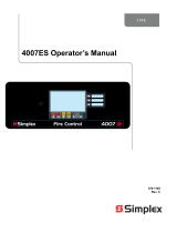
Simplex 4007ES Panels User manual
- Category
- Fire protection
- Type
- User manual

Features
Satisfies a variety of new and retrofit applications
4.3” (109 mm) diagonal color touchscreen display:
Provides detailed system status and point information
Supports dual language selection, including unicode
character languages
A custom background display appears when operation is
normal (see page 6 for details)
Eight Point Zone/Relay Module:
Each point is selectable as an IDC input or Relay output,
Class A IDCs require 2 points (one out and one return);
one module is standard, up to 3 additional modules can
be field installed for a total of 4 eight point zone/relay
modules per system
Each point on the IDC/Relay Module can be configured
as a control relay rated 2 A @ 30 VDC (resistive) as
either normally open or normally closed
Can be powered directly from the power supply or
through the optional 25 VDC Regulator Module
IDC end-of-line resistor value can be selected from a
wide range of resistance values for retrofit convenience
Electrically isolated IDNet+ addressable initiating
device SLC:
Provides built-in short circuit isolation for monitoring
and control of TrueAlarm analog sensors and IDNet
communications monitoring and control devices; for use
with either shielded or unshielded, twisted or untwisted
single pair wiring; outputs are Class A or Class B
Standard panel SLC provides up to 100 addressable
points; optional additional loop expansion modules
provide an additional isolated loop with short circuit
isolation for the IDNet+ channel; each loop expansion
module also provides an additional 75 addressable points
Power Supply Features:
Four Notification Appliance Circuits (NACs) selectable
as Class A or Class B with 6 A total available current
NAC end-of-line resistor value can be selected from a
wide range of resistance values for retrofit convenience
Additional notification power capacity is available using
the 4009 IDNet NAC Extender
Battery backup charging of up to 33 Ah; up to 18 Ah for
cabinet mounted batteries and up to 33 Ah batteries for
mounting in close-nippled remote battery cabinet
General Mechanical:
Red or platinum cabinet; rated NEMA 1 and IP30
4007ES Listings reference:
UL 864 - Control Units, System (UOJZ); Control Unit
Accessories, System, Fire Alarm (UOXX); Control
Units, Releasing Device Service (SYZV)
UL 2017 - Emergency Alarm System Control Units (CO
detection), (FSZI)
ULC-S559 - Central Station Fire Alarm System Units
(DAYRC)
ULC-S527 - Control Units, System, Fire Alarm
(UOJZC); Control Unit Accessories, System, Fire Alarm
(UOXXC); Control Units, Releasing Device Service
(SYZVC)
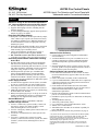
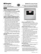
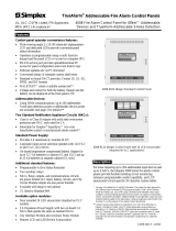
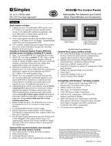
4007ES Hybrid Panel Front View
Software Feature Summary:
Current and previous panel configuration maintained in
on-board memory
An internal Ethernet service port is available for service
computer connections to perform configuration updates,
downloads and uploads; report downloads, and system
software
Internal USB interface allows a memory stick to store job
revisions, update revised jobs and panel software, and save
detailed system reports from the panel
Optional modules and connections include:
Fire Alarm Network Interface for Peer-to-Peer fire alarm
network communications, supports either Class B or Class
X operation
Point or Event DACT assembly for IP Communicators
Up to two additional IDNet+ addressable device output loop
connections with short circuit fault protection and with 75
additional point capacity each
Front mounted 48 LED annunciator with custom label
inserts; LEDs are programmable for up to 24 IDC zones of
alarm and trouble annunciation or other custom
annunciation requirements
Remote LED annunciator support via RUI communications
port for use with UTP wiring
Dual RS-232 ports (for printer, PC annunciator or third party
interface)
TrueInsight Remote Gateway
Alarm relays and auxiliary relays
City connections, with or without disconnect switch
4003EC Voice Control Panels
4009 IDNet NAC Extenders to extend NAC capability for
power and distance
Battery brackets for seismic area protection (see page 2)
* This product has been approved by the California State Fire Marshal (CSFM)
pursuant to Section 13144.1 of the California Health and Safety Code. See
CSFM Listing 7165-0026:0378 for allowable values and/or conditions
concerning material presented in this document. NYC Fire Dept COA #6191A.
Additional listings may be applicable; contact your
local Simplex product supplier for the latest status. Listings and approvals
under Simplex Time Recorder Co. are the property of Tyco Fire Protection
Products.
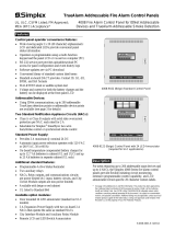
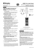
4007ES Fire Control Panels
UL, ULC, CSFM Listed; 4007ES Hybrid, Fire Detection and Control Panel with
FM, NYC Fire Dept Approved* Addressable and/or Conventional Initiation
S4007-0001-10 1/2017

Introduction
4007ES Series Fire Detection and Control Panels
provide extensive installation, operator, and service features
with point and module capacities suitable for a wide range of
system applications. Panels can be configured for stand-alone
or networked fire control operation. The convenient and
intuitive color touchscreen provides easy access for typical
system response actions and for detailed system review or
configuration updates with password control to limit user
access.
Flexible for new and retrofit applications. Standard
conventional IDCs and addressable IDNet+ communications
provide flexibility for both new and retrofit systems. IDC and
NAC end-of-line resistor values are selectable to match a wide
range of existing initiating device circuits and notification
appliance circuits.
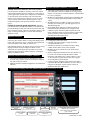
Operator Interface
Convenient Status Information. With the locking door
closed, the glass window allows viewing of the display status
LEDs. The user interface is a 4.3” diagonal color touchscreen
LCD with separate status LEDs as shown below.
LED indicators describe the general category of activity being
displayed with the LCD providing more detail. For the
authorized user, unlocking the door provides access to the
control functions and allows further inquiry by scrolling the
display for additional detail.
Operator Interface and Software Features
Convenient and detailed operator information is easily
accessed using a logical, menu-driven touchscreen display
with password access control
Multiple automatic and manual diagnostics for maintenance
reduction
Operator Interface Features (Continued)
Alarm and Trouble History Logs (up to 1000 entries for
each, 2000 total events) are available for viewing from the
display or for printing to a connected printer, or downloaded
to a service computer
Module level ground fault searching assists installation and
service by locating and isolating modules with grounded
wiring
WALKTEST silent or audible system test performs an
automatic self-resetting test cycle and supports up to 8
WALKTEST groups
Install Mode allows grouping of multiple troubles for
uninstalled modules and devices into a single trouble
condition (typical with future phased expansion); with
future equipment and devices grouped into a single trouble,
operators can more clearly identify events from the
commissioned and occupied areas
Mechanical Description
Locking door with acrylic insert
Latching front panel assembly swings forward for
convenient internal access
Smooth box surfaces are provided for locally cutting
conduit entrance holes exactly where required
Modules are power-limited (except as noted, such as
relay modules)
Battery compartment (bottom) accepts two batteries, up
to 18 Ah, to be mounted within the cabinet without
interfering with module space; charger capacity is up to
33 Ah; for batteries greater than 18 Ah, refer to page 6
for external battery cabinet details
Cabinet assembly design has been seismic tested and is
certified to IBC and CBC standards as well as to ASCE 7
categories A through F, requires battery brackets as
detailed on data sheet S2081-0019
2 S4007-0001-10 1/2017
Touchscreen Display with LED Status Indicators (approximately full size)
AlarmIndicator
RedLED
Priority2Indicator
redLED
SupervisoryIndicator
yellowLED
TroubleIndicator
yellowLED
ACPower
green LED
Color
touchscreenLCD
3programmableLEDswithcustomlabel
insert;toptwoselectableas
redoryellow,bottomselectableas
greenoryellow
AlarmSilencedIndicator
YellowLED

3 S4007-0001-10 1/2017
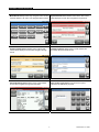
Main Menu Screen provides easy navigation to the function
required. Buttons A, B, and C have programmable functions.
System Alarm Screen identifies active alarms with custom
labels displayed, arrows allow navigation through the list
Main Menu
May 27, 2015
12:24 PM
System Trouble Screen identifies active troubles with
custom labels displayed, arrows allow navigation through
the list
Trouble Log Screen allows review of past troubles with
time stamp and point details shown.
Point Information Screen allows review of point details,
arrows allow navigation through the information.
User Access Login Screen controls access to panel
operations as determined per panel.
Operator Screen Reference

Overview. The 4007ES Hybrid provides an IDNet+
addressable initiating device Signaling Line Circuit (SLC) that
supervises wiring connections and the individual device
communications status on the SLC. With 2-wire IDNet+
SLCs, initiation, monitoring, and control devices such as
manual fire alarm stations, TrueAlarm sensors, control relays,
and sprinkler waterflow switches can communicate their
identity and status and receive fire alarm system control.
Additional addressable interface modules include circuit
isolators, conventional IDC zone adapters, and interface to
other system circuits such as fans, dampers, and elevator
controls.
IDNet+ Addressable Device Operation
Each addressable device on the IDNet+
communication channel is continuously interrogated for
status condition such as: normal, off-normal, alarm,
supervisory, or trouble. Both Class B and Class A operation
is available. Sophisticated poll and response
communication techniques ensure supervision integrity and
allow for "T-tapping" of the circuits for Class B operation.
Devices with LEDs pulse the LED to indicate receipt of a
communications poll and can be turned on steady from the
panel. With addressable devices, the location and status of
the connected device is monitored, logged, and displayed
on the operator interface LCD with each device having its
own 40 character custom label for precise identification.
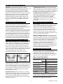
TrueAlarm Addressable Sensor Operation
Addressable initiating device communications
include operation of TrueAlarm smoke and temperature
sensors. Smoke sensors transmit an output value based on
their smoke chamber condition and the CPU maintains a
current value, peak value, and an average value for each
sensor. Status is determined by comparing the current sensor
value to its average value. Tracking this average value as a
continuously shifting reference point filters out
environmental factors that cause shifts in sensitivity.
TrueAlarm Addressable Sensor Reference
TrueAlarm Photo
Sensor with Base
TrueAlarm Photo/Heat
Sensor in CO Base
Programmable sensitivity of each sensor can be selected
at the control panel for different levels of smoke obscuration
(shown directly in percent) or for specific heat detection
levels. To evaluate whether the sensitivity should be revised,
the peak value is stored in memory and can be easily read
(or downloaded as a report) and compared to the alarm
threshold directly in percent.
CO sensor bases combine an electrolytic CO sensing
module with a TrueAlarm analog sensor to provide a single
multiple sensing assembly using one system address. The
CO sensor can be enabled/disabled, and can be used in
LED/Switch modes and custom control. (refer to data sheet
S4098-0052 for details)
TrueAlarm heat sensors can be selected for fixed
temperature detection, with or without rate-of-rise detection.
Utility temperature sensing is also available, typically to
provide freeze warnings or alert to HVAC system problems.
Readings can selected as either Fahrenheit or Celsius.
TrueSense Early Fire Detection. Multi-sensor
4098-9754 provides photoelectric and heat sensor data
using a single 40070ES IDNet+ address. The panel
evaluates smoke activity, heat activity, and their
combination, to provide TrueSense early detection. For
more details on this operation, refer to data sheet
S4098-0024.
Diagnostics and Default Device Type
Sensor Status. TrueAlarm operation allows the control
panel to automatically indicate when a sensor is almost
dirty, dirty, and excessively dirty. The NFPA 72
requirement for a test of the sensitivity range of the
sensors is fulfilled by the ability of TrueAlarm operation
to maintain the sensitivity level of each sensor. CO
Sensors track their 10 year active life status providing
indicators to assist with service planning. Indicators occur
at: 1 year, 6 months, and end of life.
Modular TrueAlarm sensors use the same base and
different sensor types (smoke or heat sensor) and can be
easily interchanged to meet specific location requirements.
This allows intentional sensor substitution during building
construction when conditions are temporarily dusty.
Instead of covering smoke sensors (causing them to be
disabled), heat sensors may be installed without
reprogramming the control panel. The control panel will
indicate an incorrect sensor type, but the heat sensor will
operate at a default sensitivity to provide heat detection
for building protection at that location.
IDNet+ Device Wiring Reference
IDNet+ Addressable Channel Capacity. The
4007ES Hybrid provides an isolated output IDNet+
signaling line circuit (SLC) that supports up to 250
addressable monitor and control points intermixed on the
same pair of wires. (250 total requires two 4007-9803
IDNet+ Loop Expansion Modules.)
IDNet+ SLC Wiring Specifications
Maximum Distance
from Control Panel
per Device Load
0 to 125 4000 ft (1219 m); 50 ohms
126-250 2500 feet (762 m); 35 ohms
Total Wire Length Allowed With
“T” Taps for Class B Wiring
Up to 12,500 ft (3.8 km);
0.60 µF
Maximum Capacitance Between
IDNet+ Channels
1 µF
Loading per device
0.8 mA supv., 1 mA alarm;
2 mA per activated device LED
Wire Type and Connections
Shielded or unshielded,
twisted or untwisted wire*
Connections
Terminal blocks for 18 to
12 AWG
Compatibility includes: IDNet communicating devices and
TrueAlarm sensors including QuickConnect and QuickConnect2
sensors; see data sheet S4090-0011 for additional reference
* Some applications may require shielded wiring. Review your
system with your local Simplex product supplier.
4 S4007-0001-10 1/2017
IDNet+ Addressable Device Control

Power Supply Output Details:
RUI Communications controls up to 10 remote devices
at up to 2500 ft (762 m) for single run, or 10,000 ft
(3048 m) total if wiring is Class B and T-tapped;
selectable as Class B or Class A
Compatible RUI remote equipment includes:
4606-9202 and 4606-9205 Color Touchscreen
Annunciators (up to 6 total), 4100 Series 24 I/O and
LED/Switch modules, 4602 Series LED/Switch and I/O
Annunciator modules, including 4602-9101 Status
Command Units (SCU), and 4602-9102 Remote
Command Units (RCU)
IDNet+ SLC Output provides electrically isolated
Class B or Class A communication; standard capacity is
up to 100 addressable points with expansion for up to
250 points using up to two 4007-9803 IDNet+ Loop
Expansion Modules (as described on page 4)
6 A Output Rating. This includes current for: special
application notification appliances; IDNet devices;
module currents; and auxiliary output current (battery
charging, CPU, and power supply current does not
subtract from the 6 A); when NACs are controlling
Regulated 24 DC Appliances, total NAC current
available is 3 A
Four on-board Class B/Class A NACs, rated 3 A each
for Special Application appliances; selectable for
SmartSync horn and strobe control, or strobe
synchronization; rated 2 A each for Regulated 24 DC
appliances
Power Supply Output Details (Continued):
NAC end-of-line (EOL) resistor values are selectable as:
10 kΩ, 3.9 kΩ, 4.7 kΩ, 5.1 kΩ, 5.6 kΩ, or 15 kΩ
Battery Charger is dual rate, temperature compensated,
and charges up to 18 Ah sealed lead-acid batteries
mounted in the battery compartment, and charges up to
33 Ah batteries mounted in an external cabinet
Battery and Charger Monitoring includes battery
charger status and low or depleted battery conditions;
status information provided to the master controller
includes analog values for: battery voltage, charger
voltage and current, actual system voltage and current,
and NAC current
Low Battery Voltage Cutout is selectable when
required (required for ULC listing applications)
2 A Auxiliary Output (AUX/SNAC) can be selected either
as resettable auxiliary power of 2 A @ 24 VDC, or
selected to be a simple NAC (SNAC) for sounder base
power, 4-wire detector power, or door holder power
Zone/Relay Module Details:
Select as IDC or Relay; configure up to 8, Class B
IDCs, or up to 4, Class A IDCs; or up to 8, Relay outputs
rated 2 A resistive @ 30 VDC (N.O. or N.C.); or
combinations of IDCs and Relays; each zone is
separately configurable as an IDC or Relay output
IDC Support. Each IDC supports up to 30, two-wire
devices
IDC EOL resistor values are selectable as: 3.3 kΩ,
2 kΩ, 2.2 kΩ, 3.4 kΩ, 3.9 kΩ, 4.7 kΩ, 5.1 kΩ, 5.6 kΩ,
6.34/6.8 kΩ, and 3.6 kΩ + 1.1 kΩ; see instructions for
more details
5 S4007-0001-10 1/2017
Factory
Programming
Options
Model Description
4007-8810 Factory Programming (select)
4007-0831 Custom Labels and Programming (requires 4007-8810)
Field Installed Optional Modules (refer to diagram on page 7 for module locations)
Model Description Supv. Alarm
4007-9801
Eight Point Zone/Relay Module, each point is selectable as an IDC input or Relay output, Class A IDCs
require 2 points (one out and one return); one module is included as standard, select up to 3 additional;
current shown is for 8 Class B IDCs with 4 in alarm, detector current is added separately
83 mA
max
351 mA
max
4007-9802
25 VDC Regulator Module; 2 A maximum output; use to power Zone/Relay modules
connected to initiating devices requiring nominal 25 VDC voltage; refer to technical
publication 579-832, 2-Wire Detector Compatibility Chart for application details
with 1 module 190 mA 445 mA
with 2 modules 290 mA 801 mA
with 3 modules 390 mA 1156 mA
4007-9803
IDNet+ Loop Expansion Module; provides an additional isolated loop with short circuit isolation to the
existing IDNet+ channel, also provides an additional 75 addressable points to the IDNet+ channel
capacity, maximum of two
NA NA
4007-9805
Panel Mounted 48 LED Status Annunciator Module; provides 24 Yellow LEDs, 20 Red
LEDs, and 4 Red/Green LEDs that are programmable for up to 24 IDC zones of alarm
and trouble annunciation, or as required for custom annunciation requirements
no LEDs on 10 mA 10 mA
with
LEDs on
1.75 mA per LED,
105 mA max
4007-9806
SDACT Module for Point or Event Reporting; order 2080-9047 connection cables as required (see cable
details under accessories)
30 mA 40 mA
4007-9807 City Circuit Module with Disconnect Switch 20 mA 36 mA
4007-9808 City Circuit Module without Disconnect Switch 20 mA 36 mA
4007-9809 Relay Module; relays for Alarm, Supervisory, and Trouble; rated 2 A resistive @ 32 VDC 15 mA 37 mA
4007-9812
Dual RS-232 Interface Module; Compatible with Simplex remote printer, PC annunciator or third party
interface (two ports/connections maximum)
60 mA 60 mA
Model* Color Description Supv. Alarm
4007-9101(BA) Red
4007ES Hybrid with 4 conventional 3 A NACs and a 6 A output power supply/battery
charger; includes IDNet+ communications for 100 addressable points and 1, 4007-9801
Zone/Relay module; Note: Add optional module and other currents separately for battery
calculations; base panel current does not subtract from the 6 A power available for
optional modules and external loads
145 mA 190 mA
4007-9102(BA) Platinum
* Models with (BA) are available assembled in the USA by adding the suffix “BA”.
Module and Accessories Selection Information
Power Supply Output and Zone/Relay Module Details
Product Selection

6 S4007-0001-10 1/2017
Field Installed Optional Modules
Model Description Supv. Alarm
4190-8001* TrueInsight Remote Service Gateway Module and Programming Selection
Required
Selection
62 mA 73 mA
4190-6106 *
TrueInsight Remote Service Gateway Module Installation Kit; includes
module and harness; configured for dynamic IP address operation unless
ordered with 4190-4016
4190-4016 *
TrueInsight Remote Service Gateway Module for fixed IP Addressing; optional, select if application will use fixed IP
address
4007-9810
Network Interface Card; Modular Network Interface; requires two media modules (below).
30 mA (with no
cards installed)
30 mA
4007-9813
Wired Media Module
Select media cards as required; mounts to
4007-9810 NIC; Class B or Class X operation
55 mA 55 mA
4007-9814
Fiber Optic Media Module 25 mA 25 mA
* Refer to data sheet S4100-0063 for additional TrueInsight Service Gateway details
Batteries
Model Capacity Battery Mounting Details
2081-9272 6.2 Ah
12 V Batteries for cabinet mounting; select one battery model per system standby requirements; order quantity of
two; to be wired in series for 24 VDC
2081-9274 10 Ah
2081-9288 12.7 Ah
2081-9275 18 Ah
2081-9287 25 Ah For remote mount in Battery Box 4009-9801
Batteries for remote mounting; see battery cabinet details
below
2081-9271 33 Ah For remote mount in Battery Box 4009-9802
Battery Accessories
Model Color Capacity Dimensions Description
4009-9801 Beige
For up to 25 Ah
batteries
16 ¼” W x 13 ½” H x 5 ¾” D
(413 mm x 343 mm x 146 mm)
External battery cabinet without charger, with locking solid
door and battery harness; for close-nippled mounting to fire
alarm control panel cabinet
4009-9802 Beige
For up to 33 Ah
batteries
25 ¾” W x 20 ¾” H x 4 ” D
(654 mm x 527 mm x 105 mm)
Accessories
Model Description
2080-9047 DACT cable, 14 ft (4.3 m) long, RJ45 plug one end, spade lugs on the other; order one per phone line connection required
2975-9812 Red semi-flush box trim; 1
7
⁄
16
” (37 mm) wide, four corners and trim pieces for top, bottom, and sides
2975-9813 Platinum semi-flush box trim; 1
7
⁄
16
” (37 mm) wide, four corners and trim pieces for top, bottom, and sides
2081-9031
Series resistor for WSO, IDCs (N.O. water flow and tamper on same circuit, wires after water flow and before tamper) 470 ,
1 W, encapsulated, two 18 AWG leads (0.82 mm
2
), 2 ½” L x 1 ” W x 1” H (64 mm x 35 mm x 25 mm). This is for non-
addressable initiating zones.
4081-9002 3.3 k, 1 W end-of-line resistor for Class B non-addressable initiating zones
4081-9018 10 k, 1 W end-of-line resistor harness for non-addressable NACs
Input Power
120 VAC Input 2 A maximum @ 102 to 132 VAC, 50/60 Hz
240 VAC Input 1 A maximum @ 204 to 264 VAC, 50/60 Hz
4007ES Hybrid Power
Supply Output Ratings
Power Supply
Output Rating
Including module currents and auxiliary power outputs;
6 A total
Output switches to
battery backup
during mains AC
failure or brownout
conditions
NAC Ratings
3 A each for Special Application Appliances
2 A each for Regulated 24 DC Appliances
Auxiliary Power Tap 2 A maximum, 24 VDC nominal (19.5 to 31.1 VDC)
Special Application Non-Addressable
Appliances
Simplex horns, strobes, and combination horn/strobes and speaker/strobes
(contact your Simplex product representative for compatible appliances)
Regulated 24 DC Non-Addressable Appliances
Power for other UL listed appliances; use associated external synchronization
modules where required
Battery Charger
Ratings
(sealed lead-acid
batteries)
Battery capacity range
UL and ULC listed for battery charging of 6.2 Ah up to 33 Ah (batteries larger
than 18 Ah require a remote battery cabinet)
Charger characteristics
and performance
Temperature compensated, dual rate, recharges depleted batteries within 48
hours per UL Standard 864; to 70% capacity in 12 hours per ULC Standard
S527
Module and Accessories Selection Information (Continued)
General Specifications

16" (406 mm)
20-7/8" (530 mm)
20-3/16"
(512 mm)
4-7/16" Deep (112 mm)
Exposed box for semi-flush mounting
1-3/4" (44 mm) minimum
Side View Reference
Finished wall surface (including
semi-flush Trim Kit if used)
A
B
E
F
J K
I
D
H
G
L
C
M
Module Locations:
A. CPU and User Interface assembly.
B. Location for optional 4007-9805 LED Module.
C. Power Supply Assembly.
D. 4007-9806 SDACT location. Note: The SDACT includes a 650-1838 flat mounting bracket (available separately). Some pre-existing
systems with an angled SDACT bracket will need to be replaced with the flat mounting bracket when a Network Interface Card is installed.
E. Location for 4007-9801 Zone/Relay Module, 4007-9812 Dual RS-232 Interface, or (as shown) 4007-9802 25 V Regulator Module
F. Primary location for 4007-9801 Zone/Relay Module, or 4190-6106 TrueInsight Remote Service Gateway.
G. Location for additional 4007-9801 Zone/Relay Module.
H. Identical to Block G above.
I. 4007-9807 or 4007-9808 City Circuit Module, or 4007-9809 Relay Module.
J. 4007-9803 IDNet+ Loop Expansion Modules, maximum of two (two are shown).
K. Identical to block J above.
L. Block L is an additional block that sits on spacers above Block G and H. The 4007-9810 NIC can be mounted in block L with or without
modules mounted below it in blocks G and H. When fiber media cards are used and an SDACT is present, the SDACT requires a 650-
1838 flat mounting bracket (ordered separately).
M. Battery location for up to 18 Ah batteries. Note: No conduit entry or wiring in this area, 14-7/8” (378 mm) wide.
Note: A system ground must be provided for Earth Detection and transient protection devices. This connection shall be made to an
approved, dedicated Earth connection per NFPA 70, Article 250, and NFPA 780.
Custom Background Display Details
Supported file types: JPG, BMP, GIF, and PNG
Recommended image type is JPG, recommended image size is 480 x 240, and
the file size limit is 100 kb
Environmental
Operating Temperature 32° to 120°F (0° to 49° C)
Operating Humidity Up to 93% RH, non-condensing @ 90° F (32° C) maximum
Additional Technical Reference
Description Document Description Document
Installation Manual 579-1102 Single Page Operator Instructions 579-1109
Zone/Relay Module Installation Manual 579-1103 2-Wire Detector Compatibility Chart 579-832
Detailed Operator’s Manual 579-1165
7 S4007-0001-10 1/2017
4007ES Mounting and Module Location Reference
General Specifications (Continued)

4606-9205 (Platinum) Color LCD
Touchscreen Remote Annunciator
4606-9202 (Red) Color LCD
Touchscreen Remote Annunciator
4007ES Hybrid with optional 48 LED
Annunciator Module (4007-9805)
4007ES Hybrid Operator View with door open
Subject Data Sheet Subject Data Sheet
4009 IDNet NAC Extender S4009-0002 Battery and Battery Cabinet Reference S2081-0006
4003EC Voice Control Panel S4003-0002 Seismic Battery Brackets Reference S2081-0019
4606 Series Color LCD Touchscreen Remote
Annunciator
S4606-0003
Addressable Device Compatibility, IDNet
Communication Sensors and Devices
S4090-0011
Graphic I/O Modules S4100-0005 Serial DACT (SDACT) S2080-0009
4602 Series SCU/RCU S4602-0001 TrueInsight Remote Service S4100-0063
Agent Release Accessories S2080-0010 Network Communications S4100-0056 S4100-0056
Fire Alarm Network Overview S4100-0055 Multi-Signal Fiber Optics S4100-0049 S4100-0049
Network Communications S4100-0056 PC Annunciator S4190-0013 S4190-0013
Automatic Extinguishing, Deluge and
Preaction Sprinkler System Releasing Control
for 4007ES
S4007-0003 120 VAC Desktop Remote Printer S4190-0011
Tyco Fire Protection Products • Westminster, MA • 01441-0001 • USA S4007-0001-10 1/2017
www.simplex-fire.com
© 2017 Tyco Fire Protection Products. All rights reserved. All specifications and other information shown were current as of document revision date and are subject to change without notice.
TYCO, SIMPLEX, and the product names listed in this material are marks and/or registered marks. Unauthorized use is strictly prohibited. NFPA 72 and National Fire Alarm Code
are trademarks of the National Fire Protection Association (NFPA).
4007ES Hybrid Additional Reference
Additional Compatible Equipment and Reference
-
 1
1
-
 2
2
-
 3
3
-
 4
4
-
 5
5
-
 6
6
-
 7
7
-
 8
8


Simplex 4007ES Panels User manual
- Category
- Fire protection
- Type
- User manual
Ask a question and I''ll find the answer in the document
Finding information in a document is now easier with AI
Related papers
-
 Simplex 4007ES Panels User manual
-
 Simplex 4007-9202 Installation guide
-
Simplex 4009 IDNet NAC Extender User manual
-
 Simplex 4007ES Panels User & Installation Manual
-
 Simplex TrueAlarm 4008-9102 User manual
-
 Simplex MINIPLEX 4100ES Series Quick start guide
-
 Simplex 4007ES Panels User manual
-
 Simplex 4010-9701 User manual
-
 Simplex TrueAlarm 4008-9102 User manual
-
 Simplex MINIPLEX 4100ES Series User manual


Other documents
-
GE Security FireShield FS302 Installation guide
-
EDWARDS E-IDC1B Analog Single Input Mini Module Installation guide
-
Dell PowerSwitch S4148U-ON Quick start guide
-
-
 Ravel RE-717MM Installation And Maintenance Instructions
-
Panasonic Smoke Alarm 2318 User manual
-
SEFRAM BK 9800_Series User manual
-
Leviton 41OUM-B User guide
-
B&K Precision Model 9801 User manual
-
Barclay 4190-48-CP Dimensions Guide
