Page is loading ...

EVAL-AD7176-2SDZ User Guide
UG-478
One Technology Way • P. O. Box 9106 • Norwood, MA 02062-9106, U.S.A. • Tel: 781.329.4700 • Fax: 781.461.3113 • www.analog.com
Evaluation Board for the AD7176-2—24-Bit, 250 kSPS Sigma-Delta ADC with
20 μs Settling
PLEASE SEE THE LAST PAGE FOR AN IMPORTANT
WARNING AND LEGAL TERMS AND CONDITIONS.
Rev. A | Page 1 of 40
FEATURES
Full featured evaluation board for the AD7176-2
PC control in conjunction with the system demonstration
platform (EVAL-SDP-CB1Z)
PC software for control and data analysis (time domain)
Standalone capability
ONLINE RESOURCES
Evaluation Kit Contents
EVAL-AD7176-2SDZ evaluation board
Evaluation software CD for the AD7176-2
Documents Needed
AD7176-2 data sheet
EVAL-AD7176-2SDZ (UG-478) user guide
Required Software
EVAL-AD7176-2SDZ evaluation software
EQUIPMENT NEEDED
EVAL-AD7176-2SDZ evaluation board
EVAL-SDP-CB1Z system demonstration platform
External 7 V to 9 V power supply
DC signal source
USB cable
PC running Windows with USB 2.0 port
GENERAL DESCRIPTION
The E VA L-AD7176-2SDZ evaluation kit features the AD7176-2
24-bit, 250 kSPS analog-to-digital converter (ADC). A 7 V to
9 V external bench top supply is regulated to 5 V and 3.3 V to
supply the AD7176-2 and support all necessary components.
The E VA L-AD7176-2SDZ board connects to the USB port of
the PC by connection to the E VAL -SDP-CB1Z motherboard.
The E VA L-AD7176-2SDZ software fully configures the
AD7176-2 device register functionality and provides dc time
domain analysis in the form of waveform graphs, histograms,
and associated noise analysis for ADC performance evaluation.
The E VA L-AD7176-2SDZ is an evaluation board that is
designed to allow the user to evaluate the features of the ADC.
The user PC software executable controls the AD7176-2 over
the USB through the system demonstration platform board
(EVA L -SDP-CB1Z).
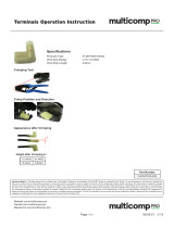
FUNCTIONAL BLOCK DIAGRAM
Figure 1. EVAL-AD7176-2SDZ Block Diagram
11035-001
AVDD1
AVSS GPIO0
GPIO1 XTAL1 CLKIO/XTAL2 DGND
REF–
REF+
REFOUT
AVDD2
REGCAPA
AIN0
AIN1
AIN2
AIN3
AIN4
1.8V
LDO
1.8V
LDO
INT
REF
CROSSPOINT
MULTIPLEXER
IOVDD
REGCAPD
I/O
CONTROL
SERIAL
INTERFACE
AND CONTROL
DIGITAL
FILTER
AD7176-2
PRECISION
REFERENCE
XTAL AND INTERNAL
CLOCK OSCILLATOR
CIRCUITRY
SCLK
DIN
CS
DOUT/RDY
SYNC/ERROR
TO AD7175-2
REFOUT PIN
POWER
LED
STATUS
LED
ADSP-BF527
USB
SDP-B
ADC
ADP1720
5V LDO
ADR445
5V VREF
7V TO 9V
VIN
ADP1720
3.3V LDO
ADP7104
5V LDO
ON-BOARD
NOISE TEST
AD8656
ADA4940-1
AD8656
AD8475

UG-478 EVAL-AD7176-2SDZ User Guide
Rev. A | Page 2 of 40
TABLE OF CONTENTS
Features .............................................................................................. 1
Online Resources .............................................................................. 1
Equipment Needed ........................................................................... 1
General Description ......................................................................... 1
Functional Block Diagram .............................................................. 1
Revision History ............................................................................... 2
EVA L-AD7176-2SDZ Quick Start Guide ...................................... 3
Evaluation Board Hardware ............................................................ 4
Device Description ....................................................................... 4
Hardware Link Options ............................................................... 4
Power Supplies .............................................................................. 6
Serial Interface .............................................................................. 6
Analog Inputs.................................................................................6
Sockets/Connectors ......................................................................7
Reference Options .........................................................................8
Using the On-Board Amplifiers ..................................................8
Evaluation Board Setup Procedures ........................................ 11
Evaluation Board Software ............................................................ 12
Software Installation Procedures.............................................. 12
Setting Up the System for Data Capture ................................. 15
Software Operation .................................................................... 16
Evaluation Board Schematics and Artwork ................................ 21
Bill of Materials ............................................................................... 30
REVISION HISTORY
4/14—Rev. 0 to Rev. A
Changes to the Reference Options Section ................................... 8
11/12—Revision 0: Initial Version

EVAL-AD7176-2SDZ User Guide UG-478
Rev. A | Page 3 of 40
EVAL-AD7176-2SDZ QUICK START GUIDE
To begin using the evaluation board, do the following:
1. With the EVAL -SDP-CB1Z board disconnected from the
USB port of the PC, install the AD7176-2 evaluation board
software from the CD included in the evaluation board kit.
The PC must be restarted after the software installation is
complete. (For complete software installation instructions,
see the Software Installation Procedures section.)
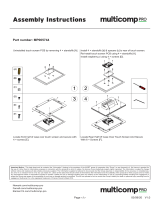
2. Connect the E VAL -SDP-CB1Z board to the E VA L -
AD7176-2SDZ board as shown in Figure 2.
a. Screw the two boards together using the plastic screw-
washer set included in the evaluation board kit to
ensure that the boards are connected firmly together.
3. Apply an external voltage in the range of 7 V to 9 V to the
J4 or J5 connecter of the E VAL -AD7176-2SDZ board, as
shown in Figure 2 (see Table 3 for more information). This
provides the power supply for the board.
4. Connect the E VAL -SDP-CB1Z board to the PC using the
supplied USB cable. If you are using Windows® XP, you may
need to search for the E VA L-SDP-CB1Z drivers. Choose
to automatically search for the drivers for the EVA L-SDP-
CB1Z board if prompted by the operating system.
5. Launch the EVA L -AD7176-2SDZ software from the
Analog Devices subfolder in the Programs menu.
Figure 2. Hardware Configuration—Setting Up the EVAL-AD7176-2SDZ
11035-002

UG-478 EVAL-AD7176-2SDZ User Guide
Rev. A | Page 4 of 40
EVALUATION BOARD HARDWARE
DEVICE DESCRIPTION
The AD7176-2 is a low noise, fast settling, multiplexed, 2-/4-
channel (fully differential/pseudo differential) Σ-Δ ADC. The
AD7176-2 has a maximum channel-to-channel scan rate of
50 kSPS (20 µs) for fully settled data. The output data rates
range from 5 Hz to 250 kHz.
Complete specifications for the AD7176-2 are provided in the
product data sheet and should be consulted in conjunction with
this user guide when using the evaluation board. Full details
about the EVA L-SDP-CB1Z are available on the Analog
Devices, Inc., website.
HARDWARE LINK OPTIONS
The default link options are listed in Table 1. By default, the
board is configured to operate from the external bench top
power supply via Connector J4. The supply required for the
AD7176-2 comes from the on-board ADP1720 LDOs, which
generate their input voltage from J4.
Table 1. Default Link and Solder Link Options
Link No. Default Option Description
LK1 A Connects the AVDD1 voltage to the power supply sequencer, ADM1185.
When AVDD1 equals 5 V, LK1 must be in Position A.
When AVDD1 equals 2.5 V, LK1 must be in Position B.
LK2 A Selects the connector for the external 7 V to 9 V power supply.
In Position A, this link selects the external 7 V to 9 V power supply to come from Connector J4.
In Position B, this link selects the external 7 V to 9 V power supply to come from Connector J5.
LK5 to LK9 Inserted Inserting LK5 to LK9 sets up the on-board noise test. In this mode, all inputs are shorted to the REFOUT pin.
SL1 A Sets the voltage applied to the AVDD2 pin.
In Position A, this link sets the voltage applied to the AVDD2 pin to be the same voltage applied to the
AVDD1 pin.
In Position B, this link sets the voltage applied to the AVDD2 pin to be a 3.3 V supply from the ADP1720-3.3 (U10)
regulator or from an external voltage.
AVDD2 cannot be set to 3.3 V when AVDD1 equals 2.5 V and AVSS equals −2.5 V.
SL2 A Sets the voltage applied to the AVDD1 pin.
In Position A, this link sets the voltage applied to the AVDD1 pin to be a 5 V supply from the ADP1720-5 (U7)
regulator or a 2.5 V supply from the ADP1720 (U4) regulator.
In Position B, this link sets the voltage applied to the AVDD1 pin to be supplied from an external voltage
source via Connector J9.
When AVDD1 equals 2.5 V, AVSS can be set to −2.5 V using an external supply connected to Connector J9. The
AVSS to AGND solder links must be removed when a split power supply is used.
SL3, SL7 A, A With SL3 and SL7 in Position A, AVDD1 is supplied with 5 V from ADP1720-5 (U7) regulator.
With SL3 and SL7 in Position B, AVDD1 is supplied with 2.5 V from the ADP1720 (U4) regulator.
SL4 A With this link in Position A, the AIN4 analog input on the AD7176-2 device is connected to Connector J8.
With this link in Position B, the AIN4 analog input is connected to the REFOUT pin of the AD7176-2.
With this link in Position C, the AIN4 analog input is connected to ground for use with four pseudo
differential inputs, if required.
SL5 B With this link in Position A, the IOVDD supply is provided from an external source via Connector J9.
With this link in Position B, the 3.3 V supply is generated by the ADP1720-3.3 (U10) regulator.
The evaluation system operates with 3.3 V logic.
SL6 Not Inserted Allows an external crystal or clock to be used as the clock source for the AD7176-2.
With SL6 not inserted, a crystal is connected to the AD7176-2.
With SL6 in Position B, an external clock source can be supplied to the ADC.
SL8 B With this link in Position A, the AIN1 analog input on the AD7176-2 device is connected to Connector J8.
With this link in Position B, the analog input applied via Connector J8 is buffered using the AD8656 before
being applied to the AIN1 pin.
With this link in Position C, the analog input path includes the ADA4940-1 differential amplifier; therefore,
in conjunction with AIN0, a single-ended to differential driver is implemented.
With this link in Position D, AIN1 is connected to Header J10.

EVAL-AD7176-2SDZ User Guide UG-478
Rev. A | Page 5 of 40
Link No. Default Option Description
SL9 B With this link in Position A, the AIN2 analog input on the AD7176-2 device is connected to Connector J8.
With this link in Position B, the analog input applied via Connector J8 is buffered using the AD8656 before
being applied to the AIN2 pin.
With this link in Position C, the analog input path includes the AD8475 amplifier; therefore, in conjunction
with AIN3, an attenuating single-ended to differential driver is implemented.
SL10 B With this link in Position A, the AIN3 analog input on the AD7176-2 device is connected to Connector J8.
With this link in Position B, the analog input applied via Connector J8 is buffered using the AD8656 before
being applied to the AIN3 pin.
With this link in Position C, the analog input path includes the AD8475 amplifier; therefore, in conjunction
with AIN2, an attenuating single-ended to differential driver is implemented.
SL11 B With this link in Position A, the AIN0 analog input on the AD7176-2 device is connected to Connector J8.
With this link in Position B, the analog input applied via Connector J8 is buffered using the AD8656 before
being applied to the AIN0 pin.
With this link in Position C, the analog input path includes the ADA4940-1 differential amplifier; therefore,
in conjunction with AIN1, a single-ended to differential driver is implemented.
With this link in Position D, AIN0 is connected to Header J10.
AVSS to
AGND
When these links are inserted, AVSS is tied to AGND. When AVSS is set to −2.5 V, these links must be
removed.
On-Board Connectors
Table 2 provides information about the external connectors on the EVA L-AD7176-2SDZ.
Table 2. On-Board Connectors
Connector
Function
J1 A 120-pin connector that mates with the EVAL-SDP-CB1Z (black colored controller board).
J4
Bench top power supply voltage input. Apply 7 V to 9 V and GND (0 V) to this connector to power the
evaluation board.
J5 Wall wart (dc plug) power supply voltage input. Apply 7 V to 9 V and GND (0 V) to this connector to
power the evaluation board.
J8 Main analog input connector. Connections to AIN0 to AIN4 are available, along with GND connections.
J9 Optional external connector, allowing external bench top or alternative supply for AVDD1, AVDD2, and
VIO supplies. When split supplies are used, AVSS is supplied externally via J9.
J10 A 7-pin connector that can be used to connect an external amplifier to Pin AIN0 and Pin AIN1 of the
AD7176-2.
J13 A 7-pin connector that allows connection to Pin AIN0 and Pin AIN1 of the AD7176-2.

UG-478 EVAL-AD7176-2SDZ User Guide
Rev. A | Page 6 of 40
POWER SUPPLIES
The evaluation board requires that an external power supply—
either a bench top supply or a wall wart (dc plug) supply—be
applied to J4 or J5 (see Table 3 for more information). Linear
regulators generate the required power supply levels from the
applied V
IN
rail. The regulators used are the 5 V ADP1720 (U7)
and the 2.5 V ADP1720 (U4), which supply 5 V and 2.5 V,
respectively, to AVDD1/AVDD2 of the ADC. The 3.3 V
ADP1720 (U10) delivers 3.3 V to the IOVDD pin of the
AD7176-2.
When a split power supply is used, the AVSS voltage must be
applied from an external source via Connector J9. AVDD1/
AVDD2 and IOVDD can also be provided via Connector J9.
However, the 7 V to 9 V supply is still required because the
on-board reference (ADR445) is supplied from this power supply.
Each supply is decoupled at the point where it enters the board
and again at the point where it connects to each device (see
the schematics shown in Figure 25 to Figure 28 to identify
decoupling points).
SERIAL INTERFACE
The AD7176-2 evaluation board connects via the SPI to the
Blackfin® ADSP-BF527 on the E VAL -SDP-CB1Z. There are four
primary signals: CS, SCLK, DIN, and DOUT/
RDY
(all are
inputs, except for DOUT/
RDY
, which is an output.)
If you wish to operate the EVA L-AD7176-2SDZ in standalone
mode, the AD7176-2 serial interface lines can be disconnected
from the 120-pin header by removing the 0 Ω links, R9 through
R13. The test points can then be used to fly-wire the signals to
an alternative digital capture setup.
ANALOG INPUTS
The E VA L-AD7176-2SDZ primary analog inputs can be applied
in two ways:
• Using J8, the green screw in terminal connector on the
right hand side of the board.
• Using the A0 to A4 SMB/SMA footprints on the evaluation
board.
The AIN0 to AIN3 analog inputs are routed via the AD8656
buffers to the associated input pins on the AD7176-2, and the
AIN4 analog input is connected to Connector J8 if LK5 to LK9
are removed, disabling the on-board noise test. The buffers are
configured for a gain of 2.
The E VA L-AD7176-2SDZ software is set up to analyze dc
inputs to the ADC.
Table 3. Required External Power Supply
1
Power Supply
(V
IN
) Applied To
Voltage Range Function
J4 7 V to 9 V Bench top supply to the evaluation board. Supplies LDOs that create 5 V, 2.5 V, and 3.3 V rails. It also
supplies the ADR445 external reference. Ensure that LK2 is set to Position A when the external power
supply is applied to this connector.
J5 7 V to 9 V Wall wart (dc plug) supply to the evaluation board. Supplies LDOs that create 5 V, 2.5 V, and 3.3 V rails.
It also supplies the ADR445 external reference. Ensure that LK2 is set to Position B when the external
power supply is applied to this connector.
1
Only a single supply is required, either J4 or J5. This can be selected using LK2.

EVAL-AD7176-2SDZ User Guide UG-478
Rev. A | Page 7 of 40
SOCKETS/CONNECTORS
Table 4. Connector Details
Connector Function Connector Type Manufacturer/Part No. Order No.
J1
Connector to
EVAL-SDP-CB1Z
120-way connector, 0.6 mm pitch Hirose FX8-120S-SV(21) Farnell 1324660
J2 External MCLK (SMA/SMB) Straight PCB mount SMB/SMA jack Tyco 1-1337482-0 Not inserted
A0 to A4 Analog inputs to ADC Straight PCB mount SMB/SMA jack Tyco 1-1337482-0 Not inserted
J4 External bench top voltage
supply for
EVAL-AD7176-2SDZ
3-pin socket terminal block,
3.81 mm pitch
Phoenix Contact MC 1,5/ 3-G-3,81 Farnell 3704737
J5
External wall wart voltage supply
(7 V to 9 V) for EVAL-AD7176-
2SDZ
DC power connectors, 2 mm SMT
power Jack
Kycon KLDX-SMT2-0202-A
Mouser 806-KLDX-
SMT20202A
J8
Analog input screw terminal
block; wired connection to
external source or sensor
8-pin terminal header, 3.81 mm pitch,
vertical
Phoenix Contact MC 1.5/ 8-G-3.81
Farnell 3704774
J9 External bench top voltage supply
option for AVDD1/AVDD2 and
IOVDD inputs on
AD7176-2 device
Screw terminal block, 3.81 mm pitch Phoenix Contact 1727036 Farnell 370-4592
J10 External amplifier connector 7-pin, SSW, 2.54 mm vertical socket Samtec SSW-107-01-T-S Farnell 1803478
J13 Connects to AIN0/AIN1 analog
inputs of ADC
7-pin, SIP, 2.54 mm through hole
header
Samtec TLW-107-05-G-S Farnell 1668499

UG-478 EVAL-AD7176-2SDZ User Guide
Rev. A | Page 8 of 40
REFERENCE OPTIONS
The EVA L -AD7176-2SDZ includes an external 5 V reference (the
ADR445) and an internal 2.5 V reference. The default operation
on the AD7176-2 is to use the internal 2.5 V reference.
The reference used for a conversion is selected by choosing the
reference in the SETUPCONx registers associated with Setup 1,
Setup 2, Setup 3, and Setup 4.
Switch between using the internal reference and external reference
by accessing the AD7176-2 register map via the evaluation soft-
ware. Figure 3 shows how to select the reference source for
Setup 1, Setup 2, Setup 3, and Setup 4. Figure 4 shows the
ADCMODE register setting that enables the internal reference.
Figure 3. Selecting the Reference Source for
Setup 1, Setup 2, Setup 3, and Setup 4
Figure 4. Turning On the Internal 2.5 V Reference
USING THE ON-BOARD AMPLIFIERS
The AD7176-2 evaluation board contains three front-end configu-
rations. The AD8656 is provided for buffering the analog inputs
of the AD7176-2. By default, it is configured for a gain of 2, and
the front-end is selected on the evaluation board. The ADA4940-1
amplifier provides a single-ended to differential driver, whereas
the AD8475 is configured to operate as an attenuating single-ended
to differential driver. Figure 5 shows the location of the R and C
components on the AD7176-2 evaluation board. Figure 6 and
Figure 7 highlight the R and C components that are populated
on the board for each amplifier, and Table 5 to Table 7 list the
component values.
Figure 5. Identification of R/C Components for the Amplifiers
11035-034

EVAL-AD7176-2SDZ User Guide UG-478
Rev. A | Page 9 of 40
Figure 6. Setup for the AD8656 Amplifiers
Table 5. R/C Values Used with AD8656 Amplifiers (Gain = 2)
U8 U12
Component Status Component Status
R65 0 Ω R107 0 Ω
R68 1 kΩ, 0.1% R109 1 kΩ, 0.1%
R72
1
0 Ω R110
2
0 Ω
R91 10 Ω R115 10 Ω
R92 1 kΩ, 0.1% R116 1 kΩ, 0.1%
R93 0 Ω R117 0 Ω
R99 1 kΩ, 0.1% R119 1 kΩ, 0.1%
R100
1
0 Ω R120
2
0 Ω
R105 10 Ω R125 10 Ω
R106 1 kΩ, 0.1% R126 1 kΩ, 0.1%
R34 0 Ω R46 0 Ω
R39 0 Ω R47 0 Ω
C19 270 pF C27 270 pF
C59 270 pF C28 270 pF
C23
680 pF
C26
680 pF
1
Remove R72 and R100 when connecting the ADA4940-1 to the AD7176-2.
2
Remove R110 and R120 when connecting the AD8475 to the AD7176-2.
0.1µF
+5V
R91
R92
R105
R72
R100
R34
R39
R65
R93
AD8656
R68
R106
R99
IN0
IN1
C19
C59
C23
0.1µF
R119
+5V
R126
R115
R110 R47
R125
R120 R46
R107
R117
AD8656
R116
R109
IN2
IN3
C28
C27
C26
3
REF+
2
REF–
21
AIN0
22
AIN1
23
AIN2
4
REFOUT
24
AIN3
6
AVSS
7
AVDD1
8
AVDD2
0.1µF
+5V
0.1µF 0.1µF
AD7176-2
+5V
0.1µF
4.7µF0.1µF
ADR445
*
5V VREF
0.1µF
*USING ADR444 (4.096V REFERENCE) IN PLACE OF
THE ADR445 ALLOWS THE ENTIRE CCT TO BE
OPERATED FROM A SINGLE +5V SUPPLY RAIL.
13
12
11
14
SCLK
DIN
CS
DOUT/RDY
11035-035

UG-478 EVAL-AD7176-2SDZ User Guide
Rev. A | Page 10 of 40
Figure 7. Setup for the ADA4940-1 and AD8475 Amplifiers
Table 6. R/C Components for ADA4940-1 (Single-Ended to Differential Driver)
Component Status
R66 0 Ω
R75 0 Ω
R76 0 Ω
R77 0 Ω
R96
1
Not inserted
R97
1
Not inserted
R98 0 Ω
R34
0 Ω
R39
0 Ω
C19
270 pF
C59 270 pF
C23 680 pF
1
Insert 0 Ω resistors in R96 and R97 to connect the ADA4940-1 to the AD7176-2, and place the SL8 and SL11 solder links in Position C. Ensure that the R72 and R100
resistors are removed.
Table 7. R/C Components for AD8475 (Attenuating Single-Ended to Differential Driver)
Component Status
R63 0 Ω
R64
1
Not inserted
R74
1
Not inserted
R78 0 Ω
R46 0 Ω
R47 0 Ω
C27 270 pF
C28 270 pF
C26 680 pF
1
Populate R64 and R74 with 10 Ω resistors to connect the AD8475 to the AD7176-2, and place the SL9 and SL10 solder links in Position C. Ensure that the R110 and R120
resistors are removed.
11035-036
R96
R97
R34
R39
C19
C59
C23
R64
R47
R74
R46
C28
C27
C26
3
REF+
2
REF–
21
AIN0
22
AIN1
23
AIN2
4
REFOUT
24
AIN3
6
AVSS
7
AVDD1
8
AVDD2
0.1µF
+5V
0.1µF 0.1µF
AD7176-2
+5V
0.1µF
4.7µF
0.1µF
ADR445
5V VREF
0.1µF
13
12
11
14
SCLK
DIN
CS
DOUT/RDY
0.1µF
+5V
IN0
IN1
R96R66
R75
R77
0.1µF
+5V
IN2
IN3
AD8475
ADA4940-1
R98
R63
VOCM
VOCM
2.5V
R78
+IN 0.4×
–IN 0.4×

EVAL-AD7176-2SDZ User Guide UG-478
Rev. A | Page 11 of 40
EVALUATION BOARD SETUP PROCEDURES
After following the instructions in the Software Installation
Procedures section, set up the evaluation and SDP boards as
detailed in this section.
Warning
The evaluation software and drivers must be installed before con-
necting the evaluation board and EVA L -SDP-CB1Z board to
the USB port of the PC to ensure that the evaluation system is
correctly recognized when it is connected to the PC.
Configuring the Evaluation and SDP Boards
1. Connect the E VAL -SDP-CB1Z board to Connector A or
Connector B on the EVA L-AD7176-2SDZ board. Screw
the two boards together using the plastic screw-washer set
included in the evaluation board kit to ensure that the
boards are connected firmly together.
2. Connect the power supplies to the EVA L-AD7176-2SDZ
board. The EVA L-AD7176-2SDZ board requires an
external bench top power supply in the range of 7 V to 9 V.
Connect this supply to J4 on the E VA L -AD7176-2SDZ
board. (For more information about the required
connections and available options, refer to the Power
Supplies section.)
3. Connect the E VAL -SDP-CB1Z board to the PC using the
supplied USB cable.

UG-478 EVAL-AD7176-2SDZ User Guide
Rev. A | Page 12 of 40
EVALUATION BOARD SOFTWARE
SOFTWARE INSTALLATION PROCEDURES
The EVA L-AD7176-2SDZ evaluation kit includes a CD
containing software to be installed on your PC before you begin
using the evaluation board.
There are two parts to the installation:
• AD7176-2 evaluation board software installation
• EVA L-SDP-CB1Z system demonstration platform board
drivers installation
Warning
The evaluation software and drivers must be installed before
connecting the evaluation board and EVA L -SDP-CB1Z board to
the USB port of the PC to ensure that the evaluation system is
correctly recognized when it is connected to the PC.
Installing the AD7176-2 Evaluation Board Software
To install the AD7176-2 evaluation board software,
1. With the EVAL -SDP-CB1Z board disconnected from the
USB port of the PC, insert the installation CD into the CD-
ROM drive.
2. Double-click the setup.exe file to begin the evaluation board
software installation. The software is installed to the
following default location: C:\Program Files\Analog
Devices\AD7176-2.
3. A dialog box appears asking for permission to allow the
program to make changes to your computer. Click Ye s.
Figure 8. AD7176-2 Evaluation Software Installation:
Granting Permission for the Program to Make Changes to Your Computer
4. Select the location to install the software, and then click Next.
(Figure 9 shows the default locations, which are displayed
when the window opens, but you can select another location
by clicking Browse.)
Figure 9. AD7176-2 Evaluation Software Installation:
Selecting the Location for Software Installation
5. A license agreement appears. Read the agreement, and then
select I accept the License Agreement and click Next.
Figure 10. AD7176-2 Evaluation Software Installation:
Accepting the License Agreement
11035-005
11035-006
11035-007

EVAL-AD7176-2SDZ User Guide UG-478
Rev. A | Page 13 of 40
6. A summary of the installation is displayed. Click Next to
continue.
Figure 11. AD7176-2 Evaluation Software Installation:
Reviewing a Summary of the Installation
7. A dialog box informs you when the installation is
complete. Click Next.
Figure 12. AD7176-2 Evaluation Software Installation:
Indicating When the Installation Is Complete
11035-008
11035-009

UG-478 EVAL-AD7176-2SDZ User Guide
Rev. A | Page 14 of 40
Installing the EVAL-SDP-CB1Z System Demonstration
Platform Board Drivers
After the installation of the evaluation software is complete, a
welcome window is displayed for the installation of the EVA L-
SDP-CB1Z system demonstration platform board drivers.
1. With the EVAL -SDP-CB1Z board still disconnected from
the USB port of the PC, make sure that all other applications
are closed, and then click Next.
Figure 13. EVAL-SDP-CB1Z Drivers Setup:
Beginning the Drivers Installation
2. Select the location to install the drivers, and then click Next.
Figure 14. EVAL-SDP-CB1Z Drivers Setup:
Selecting the Location for Drivers Installation
3. Click Install to confirm that you would like to install the
drivers.
Figure 15. EVAL-SDP-CB1Z Drivers Setup:
Granting Permission to Install Drivers
4. To complete the drivers installation, click Finish, which
closes the installation wizard.
Figure 16. EVAL-SDP-CB1Z Drivers Setup:
Completing the Drivers Setup Wizard
5. Before using the evaluation board, you must restart the
computer.
Figure 17. EVAL-SDP-CB1Z Drivers Setup:
Restarting the Computer
11035-010
11035-011
11035-012
11035-013
11035-014

EVAL-AD7176-2SDZ User Guide UG-478
Rev. A | Page 15 of 40
SETTING UP THE SYSTEM FOR DATA CAPTURE
After completing the steps in the Software Installation
Procedures and Evaluation Board Hardware sections, set up the
system for data capture as follows:
1. Allow the Found New Hardware Wizard to run after the
EVA L-SDP-CB1Z board is plugged into your PC. (If you
are using Windows XP, you may need to search for the
EVA L-SDP-CB1Z drivers. Choose to automatically search
for the drivers for the EVA L-SDP-CB1Z board if prompted
by the operating system.)
2. Check that the board is connecting to the PC correctly
using the Device Manager of the PC.
a. Access the Device Manager as follows:
i. Right-click My Computer and then click Manage.
ii. A dialog box appears asking for permission to
allow the program to make changes to your
computer. Click Ye s .
iii. The Computer Management box appears. Click
Device Manager from the list of System To ols
(see Figure 18).
b. The E VA L-SDP-CB1Z board should appear under
ADI Development Tools. This indicates that the
driver software is installed and that the board is
connecting to the PC correctly.
Figure 18. Device Manager:
Checking That the Board Is Connected to the PC Correctly
Launching the Software
After completing the steps in the Setting Up the System for Data
Capture section, launch the AD7176-2 software as follows:
1. From the Start menu, select Programs > Analog Devices
> AD7176-2 > AD7176-2 Evaluation Board Software. The
main window of the software then displays.
2. If the AD7176-2 evaluation system is not connected to the
USB port via the EVA L-SDP-CB1Z when the software is
launched, a connectivity error displays (see Figure 19).
Connect the evaluation board to the USB port of the PC,
wait a few seconds, click Rescan, and then follow the on-
screen instructions.
Figure 19. Connectivity Error Alert
When the software starts running, it searches for hardware
connected to the PC. A dialog box indicates when the generic
SDP attached to the PC is detected, and then the main window
appears (see Figure 20).
11035-015
11035-016

UG-478 EVAL-AD7176-2SDZ User Guide
Rev. A | Page 16 of 40
SOFTWARE OPERATION
Overview of the Main Window
The main window of the software (see Figure 20) contains the
significant control buttons and analysis indicators of the
AD7176-2 software.
ADC Setup Button
Clicking ADC Setup, located near the top left of the main
window (see Figure 20), opens the AD7176-2 Register Interface
window.
Start Sampling Button
Clicking Start Sampling, located near the top right hand corner
of the main window (see Figure 20), starts ADC sampling; results
are reported in the graphs of the DATA and ANALYSIS sections
of the main window.
Data Graph
The graph in the upper half, or DATA section, of the main window,
shows each successive sample of the ADC output (input referred).
The indicators beside this graph show the latest data value, the
channel being converted, and the flag for the error diagnostics
of the AD7176-2. Navigation tools are provided to allow you to
control the cursor, zooming, and panning (see Figure 20).
Analysis Graph
The graph in the bottom half, or ANALYSIS section, of the
main window, shows the histogram analysis; to the right of the
graph, the respective noise analysis on the indicator is shown.
Navigation tools are provided to allow you to control the cursor,
zooming, and panning (see Figure 20).
CRC Error Indicator
This LED icon illuminates when there has been a CRC error
detected in the communications between the software and the
AD7176-2. The CRC functionality on the AD7176-2 is disabled
by default.
Exiting the Software
To exit the software, click the red X at the top right hand corner
of the main window.
Figure 20. Main Window
11035-017
NOTES
1. FOR DETAILS ABOUT THE AREAS HIGHLIGHTED IN RED, SEE THE OVERVIEW
OF THE MAIN WINDOW SECTION.
CONTROL
CURSOR
CONTROL
ZOOMING
CONTROL
PANNING

EVAL-AD7176-2SDZ User Guide UG-478
Rev. A | Page 17 of 40
Noise Test—Quick Start Demonstration
To perform a noise test using the AD7176-2 evaluation board,
LK5 to LK9 should be inserted so that the analog inputs are
connected together. The internal reference should be enabled
and made available at the REFOUT pin. The internal reference
biases the analog inputs to an appropriate voltage.
1. Click ADC Setup to open the AD7176-2 Register Interface
window. The AD7176-2 should be configured as follows:
a. In the ADCMODE register, the internal refer-
ence is enabled and outputs a buffered 2.5 V to
the REFOUT pin.
b. In the CHMAP1 register, AIN2 is connected to the
positive input, AIN3 is connected to the negative
input of the ADC for this channel, and Setup 1 is
selected. Therefore, the AIN2 to AIN3 conversion is
mapped using the Setup 1 configuration.
c. Setup 1 is configured with the following register settings:
i. In the SETUPCON1 register, the external reference
is selected as the reference source for the ADC
conversion.
ii. In the FILTCON1 register, the output data rate is
set to 1 kHz, and the fast settling filter (Sinc5 +
Sinc1) is enabled.
iii. In the OFFSET1 register, the default offset
register value is selected.
iv. In the GAIN1 register, the factory trimmed gain
error value is selected.
2. Figure 21 shows the contents of this window and the state
of the AD7176-2 registers. Click OK to return to the main
window. Figure 22 shows an example of the main window
after running a noise test.
3. Set the number of samples to be collected in each batch in
the Samples box, which is located just to the left of Start
Sampling, near the top right hand corner of the main
window.
4. Click Start Sampling to acquire samples from the ADC.
Figure 21. Configuration for Noise Test
11035-018

UG-478 EVAL-AD7176-2SDZ User Guide
Rev. A | Page 18 of 40
Figure 22. Example of the Main Window After Running a Noise Test
Reading Samples from the ADC
The evaluation board is set up to use the external 5 V on-board
reference (ADR445). To read samples from the ADC,
1. The value in the Vref box is set to 5.0000 V by default to
use the external 5 V on-board reference (ADR445). If a
different reference is used, such as the 2.5 V internal
reference, set the value in the Vref box accordingly. (The
analysis results are based on the value set in this box.)
2. Select the number of samples to analyze in the Samples
box. (Note that when performing a continuous capture,
this number is limited to 65,536 samples.)
3. When Sampling is set to Capture, a batch of samples is
read when Start Sampling is clicked, with the batch size
being set by the value in the Samples box. When Sampling
is set to Continuous, the software performs a continuous
capture from the ADC when Start Sampling is clicked.
4. Click Stop to stop streaming data.
5. Use the navigation tools within each graph to control the
cursor, zooming, and panning (see Figure 20).
6. If desired, save the current captured data for later analysis
(see Figure 24 and the Save File section).
11035-021

EVAL-AD7176-2SDZ User Guide UG-478
Rev. A | Page 19 of 40
DC Waveform Capture
The waveforms resulting from the gathered samples are shown
in the top graph of the window. The right hand side of the window
indicates which channel is selected and the value of the last sample
of the batch. The conversions can be displayed as codes or as volts.
DC Testing—Histogram
The histogram resulting from the gathered samples is shown in
the bottom graph. Parameters such as peak-to-peak noise and
rms noise are displayed to the right of the graph in the Analysis
Results section for the current batch of samples.
Figure 23. Waveform and Histogram Analysis
11035-020

UG-478 EVAL-AD7176-2SDZ User Guide
Rev. A | Page 20 of 40
Save File
The software can save the current captured data for later
analysis (see Figure 24).
1. Right-click on the waveform or histogram graph.
2. Select Export Data from the drop-down menu that
appears.
A Save dialog box is displayed, prompting you to save the data
to an appropriate folder location.
Figure 24. Exporting Data to Save Results
11035-019
/