Page is loading ...

USER MANUAL
DMC-13X8
Manual Rev. 1.0e
By Galil Motion Control, Inc.
Galil Motion Control, Inc.
3750 Atherton Road
Rocklin, California 95765
Phone: (916) 626-0101
Fax: (916) 626-0102
Internet Address: [email protected]
URL: www.galilmc.com
Rev Date: 5-06

Using This Manual
This user manual provides information for proper operation of the DMC-13X8 controller. The
appendix to this manual contains information regarding the accessories to these controllers. A separate
supplemental manual, the Command Reference, contains a description of the commands available for
use with the controller.
Your motion controller has been designed to work with both servo and stepper type motors.
Installation and system setup will vary depending upon whether the controller will be used with
stepper motors or servo motors. To make finding the appropriate instructions faster and easier, icons
will be next to any information that applies exclusively to one type of system. Otherwise, assume that
the instructions apply to all types of systems. The icon legend is shown below.
Attention: Pertains to servo motor use.
Attention: Pertains to stepper motor use.
Please note that many examples are written for the DMC-1348 four-axes controller. Users of the
DMC-1338 3-axis controller, DMC-1328 2-axes controller, or DMC-1318 1-axis controller should
note that the DMC-1338 uses the axes denoted as XYZ, the DMC-1328 uses the axes denoted as XY,
and the DMC-1318 uses the X-axis only. The axes A,B,C,D may be used interchangeably with
X,Y,Z,W for any of the DMC-13X8 regardless of the number of axes.
This manual was written for the DMC-13X8 firmware revision 1.1 and later. For a DMC-13X8
controller with firmware previous to revision 1.1, please consult the original manual for your
hardware.
WARNING: Machinery in motion can be dangerous! It is the responsibility of the user to design
effective error handling and safety protection as part of the machine. Galil shall not
be liable or
responsible for any incidental or consequential damages.

USER MANUAL Contents • 3
Contents
Using This Manual ....................................................................................................................2
Chapter 1 Overview 9
Introduction ...............................................................................................................................9
Overview of Motor Types..........................................................................................................9
Standard Servo Motor with +/- 10 Volt Command Signal........................................10
Brushless Servo Motor with Sinusoidal Commutation..............................................10
Stepper Motor with Step and Direction Signals........................................................10
DMC-13X8 Functional Elements............................................................................................10
Microcomputer Section.............................................................................................11
Motor Interface..........................................................................................................11
Communication.........................................................................................................11
General I/O................................................................................................................11
System Elements .......................................................................................................12
Motor.........................................................................................................................12
Amplifier (Driver).....................................................................................................12
Encoder......................................................................................................................13
Watch Dog Timer......................................................................................................13
Chapter 2 Getting Started 15
The DMC-13X8 Motion Controller.........................................................................................15
Elements You Need.................................................................................................................16
Installing the DMC-13X8........................................................................................................17
Step 1. Determine Overall Motor Configuration.......................................................17
Step 2. Install Jumpers on the DMC-13X8................................................................18
Step 3. Install the DMC-13X8 in the VME Host.......................................................19
Step 4. Establish Communication with the Galil controller ......................................19
Step 5. Determine the Axes to be Used for Sinusoidal Commutation.......................19
Step 6. Make Connections to Amplifier and Encoder...............................................20
Step 7a. Connect Standard Servo Motors..................................................................22
Step 7b. Connect Sinusoidal Commutation Motors...................................................26
Step 7C. Connect Step Motors ..................................................................................29
Step 8. Tune the Servo System..................................................................................29
Design Examples.....................................................................................................................30
Example 1 - System Set-up .......................................................................................30
Example 2 - Profiled Move .......................................................................................31
Example 3 - Multiple Axes........................................................................................31
Example 4 - Independent Moves...............................................................................31
Example 5 - Position Interrogation............................................................................31
Example 6 - Absolute Position..................................................................................32
Example 7 - Velocity Control....................................................................................32
Example 8 - Operation Under Torque Limit .............................................................33
Example 9 - Interrogation..........................................................................................33
Example 10 - Operation in the Buffer Mode.............................................................33
Example 11 - Using the On-Board Editor .................................................................33

4 • Contents USER MANUAL
Example 12 - Motion Programs with Loops..............................................................34
Example 13 - Motion Programs with Trippoints.......................................................34
Example 14 - Control Variables................................................................................35
Example 15 - Linear Interpolation.............................................................................35
Example 16 - Circular Interpolation..........................................................................35
Chapter 3 Connecting Hardware 37
Overview .................................................................................................................................37
Using Optoisolated Inputs .......................................................................................................37
Limit Switch Input.....................................................................................................37
Home Switch Input....................................................................................................38
Abort Input................................................................................................................38
Uncommitted Digital Inputs......................................................................................39
Wiring the Optoisolated Inputs................................................................................................39
Using an Isolated Power Supply................................................................................40
Bypassing the Opto-Isolation:...................................................................................41
Analog Inputs ..........................................................................................................................41
Amplifier Interface ..................................................................................................................41
TTL Inputs...............................................................................................................................42
TTL Outputs............................................................................................................................43
Chapter 4 Communication 45
Introduction .............................................................................................................................45
Communication with Controller..............................................................................................45
Communication Registers .........................................................................................45
Simplified Communication Procedure ......................................................................46
Advanced Communication Techniques.....................................................................46
Communication with Controller - Secondary FIFO channel...................................................47
Polling FIFO..............................................................................................................47
DMA / Secondary FIFO Memory Map.....................................................................48
Explanation of Status Information and Axis Switch Information..............................50
Notes Regarding Velocity and Torque Information ..................................................51
Interrupts..................................................................................................................................51
Setting up Interrupts..................................................................................................51
Configuring Interrupts...............................................................................................51
Servicing Interrupts...................................................................................................53
Example - Interrupts..................................................................................................53
Controller Response to DATA ................................................................................................54
Chapter 5 Command Basics 55
Introduction .............................................................................................................................55
Command Syntax - ASCII.......................................................................................................55
Coordinated Motion with more than 1 axis...............................................................56
Command Syntax – Binary......................................................................................................57
Binary Command Format..........................................................................................57
Binary command table...............................................................................................58
Controller Response to DATA ................................................................................................59
Interrogating the Controller.....................................................................................................59
Interrogation Commands...........................................................................................59
Summary of Interrogation Commands ......................................................................60
Interrogating Current Commanded Values................................................................60
Operands....................................................................................................................60
Command Summary..................................................................................................61

USER MANUAL Contents • 5
Chapter 6 Programming Motion 63
Overview .................................................................................................................................63
Independent Axis Positioning..................................................................................................64
Command Summary - Independent Axis ..................................................................65
Operand Summary - Independent Axis.....................................................................65
Independent Jogging................................................................................................................67
Command Summary - Jogging..................................................................................67
Operand Summary - Independent Axis.....................................................................67
Linear Interpolation Mode.......................................................................................................68
Specifying Linear Segments......................................................................................68
Command Summary - Linear Interpolation...............................................................70
Operand Summary - Linear Interpolation..................................................................71
Example - Linear Move.............................................................................................71
Example - Multiple Moves........................................................................................72
Vector Mode: Linear and Circular Interpolation Motion.........................................................73
Specifying the Coordinate Plane ...............................................................................73
Specifying Vector Segments .....................................................................................73
Additional commands................................................................................................74
Command Summary - Coordinated Motion Sequence..............................................76
Operand Summary - Coordinated Motion Sequence.................................................76
Electronic Gearing...................................................................................................................77
Command Summary - Electronic Gearing ................................................................78
Electronic Cam........................................................................................................................79
Command Summary - Electronic CAM....................................................................83
Operand Summary - Electronic CAM.......................................................................84
Example - Electronic CAM.......................................................................................84
Contour Mode..........................................................................................................................85
Specifying Contour Segments...................................................................................85
Additional Commands...............................................................................................87
Command Summary - Contour Mode .......................................................................87
Operand Summary - Contour Mode..........................................................................87
Stepper Motor Operation.........................................................................................................91
Specifying Stepper Motor Operation.........................................................................91
Using an Encoder with Stepper Motors.....................................................................92
Command Summary - Stepper Motor Operation.......................................................93
Operand Summary - Stepper Motor Operation..........................................................93
Stepper Position Maintenance Mode (SPM)............................................................................93
Error Limit.................................................................................................................94
Correction..................................................................................................................94
Dual Loop (Auxiliary Encoder)...............................................................................................98
Backlash Compensation ............................................................................................99
Motion Smoothing.................................................................................................................100
Using the IT and VT Commands:............................................................................100
Using the KS Command (Step Motor Smoothing):.................................................101
Homing..................................................................................................................................102
Command Summary - Homing Operation...............................................................104
Operand Summary - Homing Operation..................................................................104
High Speed Position Capture (The Latch Function)..............................................................104
Fast Update Rate Mode .........................................................................................................105
Chapter 7 Application Programming 107
Overview ...............................................................................................................................107
Using the DMC-13X8 Editor to Enter Programs...................................................................107
Edit Mode Commands.............................................................................................108

6 • Contents USER MANUAL
Program Format.....................................................................................................................108
Using Labels in Programs .......................................................................................109
Special Labels..........................................................................................................109
Commenting Programs............................................................................................110
Executing Programs - Multitasking.......................................................................................110
Debugging Programs .............................................................................................................111
Program Flow Commands.....................................................................................................113
Event Triggers & Trippoints....................................................................................113
Event Trigger Examples:.........................................................................................115
Conditional Jumps...................................................................................................117
Using If, Else, and Endif Commands ......................................................................119
Subroutines..............................................................................................................121
Stack Manipulation..................................................................................................121
Auto-Start Routine ..................................................................................................121
Automatic Subroutines for Monitoring Conditions.................................................122
Mathematical and Functional Expressions ............................................................................125
Mathematical Operators ..........................................................................................125
Bit-Wise Operators..................................................................................................125
Functions.................................................................................................................126
Variables................................................................................................................................127
Programmable Variables.........................................................................................127
Operands................................................................................................................................129
Special Operands (Keywords).................................................................................129
Arrays ....................................................................................................................................130
Defining Arrays.......................................................................................................130
Assignment of Array Entries...................................................................................130
Automatic Data Capture into Arrays.......................................................................131
Deallocating Array Space........................................................................................133
Input of Data (Numeric and String).......................................................................................133
Input of Data............................................................................................................133
Output of Data (Numeric and String) ....................................................................................134
Sending Messages ...................................................................................................134
Displaying Variables and Arrays.............................................................................135
Interrogation Commands.........................................................................................136
Formatting Variables and Array Elements..............................................................137
Converting to User Units.........................................................................................138
Hardware I/O.........................................................................................................................138
Digital Outputs........................................................................................................138
Digital Inputs...........................................................................................................139
Input Interrupt Function ..........................................................................................140
Analog Inputs..........................................................................................................141
Example Applications............................................................................................................142
Wire Cutter..............................................................................................................142
X-Y Table Controller ..............................................................................................143
Speed Control by Joystick.......................................................................................145
Position Control by Joystick....................................................................................146
Backlash Compensation by Sampled Dual-Loop....................................................146
Chapter 8 Hardware & Software Protection
149
Introduction ...........................................................................................................................149
Hardware Protection..............................................................................................................149
Output Protection Lines...........................................................................................149
Input Protection Lines .............................................................................................150
Software Protection ...............................................................................................................150
Programmable Position Limits................................................................................150

USER MANUAL Contents • 7
Off-On-Error ...........................................................................................................151
Automatic Error Routine.........................................................................................151
Limit Switch Routine ..............................................................................................151
Chapter 9 Troubleshooting 153
Overview ...............................................................................................................................153
Installation.............................................................................................................................153
Communication......................................................................................................................154
Stability..................................................................................................................................155
Operation...............................................................................................................................155
Chapter 10 Theory of Operation 157
Overview ...............................................................................................................................157
Operation of Closed-Loop Systems.......................................................................................159
System Modeling...................................................................................................................160
Motor-Amplifier......................................................................................................161
Encoder....................................................................................................................163
DAC ........................................................................................................................164
Digital Filter............................................................................................................164
ZOH.........................................................................................................................165
System Analysis.....................................................................................................................165
System Design and Compensation.........................................................................................167
The Analytical Method............................................................................................167
Appendices 171
Electrical Specifications ........................................................................................................171
Servo Control ..........................................................................................................171
Stepper Control........................................................................................................171
Input/Output............................................................................................................171
Power.......................................................................................................................172
Performance Specifications ...................................................................................................172
Connectors for DMC-13X8 Main Board...............................................................................173
Pin-Out Description for DMC-13X8.....................................................................................174
Accessories and Options........................................................................................................175
ICM-1900 Interconnect Module............................................................................................176
ICM-1900 Drawing ...............................................................................................................180
AMP-19X0 Mating Power Amplifiers...................................................................................180
ICM-2900 Interconnect Module............................................................................................181
Opto-Isolated Outputs ICM-1900 / ICM-2900 (-Opto option)..............................................184
Standard Opto-isolation and High Current Opto-isolation:.....................................184
64 Extended I/O of the DMC-13X8 Controller .....................................................................184
Configuring the I/O of the DMC-13X8...................................................................185
Connector Description:............................................................................................186
IOM-1964 Opto-Isolation Module for Extended I/O Controllers..........................................189
Description:.............................................................................................................189
Overview.................................................................................................................190
Configuring Hardware Banks..................................................................................190
Digital Inputs...........................................................................................................191
High Power Digital Outputs....................................................................................193
Standard Digital Outputs.........................................................................................194
Electrical Specifications..........................................................................................195
Relevant DMC Commands......................................................................................196
Screw Terminal Listing...........................................................................................196
Coordinated Motion - Mathematical Analysis.......................................................................198

8 • Contents USER MANUAL
DMC-13X8/DMC-1300 Comparison....................................................................................202
List of Other Publications......................................................................................................202
Training Seminars..................................................................................................................203
Contacting Us ........................................................................................................................204
WARRANTY........................................................................................................................205
Index 207

USER MANUAL Chapter 1 Overview • 9
Chapter 1 Overview
Introduction
The DMC-13X8 series motion control cards install directly into the VME bus. This controller series
offers many enhanced features including high-speed communications, non-volatile program memory,
faster encoder speeds, and improved cabling for EMI reduction.
The DMC-13X8 provides two channels for high speed communication. Both controllers use a high
speed main FIFO for sending and receiving commands. Additionally, the DMC-13X8 provides a
secondary polling FIFO for instant access to controller status and parameters. The controller allows
for high-speed servo control up to 12 million encoder counts/sec and step motor control up to 3 million
steps per second. Sample rates as low as 62.5μsec per axis are available.
A 2 meg Flash EEPROM provides non-volatile memory for storing application programs, parameters,
arrays, and firmware. New firmware revisions are easily upgraded in the field without removing the
controller from the VME backplane.
The DMC-13X8 is available with up to four axes on a single VME card. The DMC-1318, 1328, 1338
and 1348 controllers fit on a single 6U format VME card.
Designed to solve complex motion problems, the DMC-13X8 can be used for applications involving
jogging, point-to-point positioning, vector positioning, electronic gearing, multiple move sequences
and contouring. The controller eliminates jerk by programmable acceleration and deceleration with
profile smoothing. For smooth following of complex contours, the DMC-13X8 provides continuous
vector feed of an infinite number of linear and arc segments. The controller also features electronic
gearing with multiple master axes as well as gantry mode operation.
For synchronization with outside events, the DMC-13X8 provides uncommitted I/O, including 8 opto-
isolated digital inputs, 8 digital outputs and 8 analog inputs for interface to joysticks, sensors, and
pressure transducers. The DMC-13X8 controller also comes standard with an additional 64
configurable I/O. Dedicated optoisolated inputs are provided on all DMC-13X8 controllers for
forward and reverse limits, abort, home, and definable input interrupts. The DMC-13X8 is addressed
through the 16 bit short I/O space of your VME system. Vectored hardware interrupts are available to
coordinate events on the controller with the rest of the VME system. Commands can be sent in either
Binary or ASCII.
Overview of Motor Types
The DMC-13X8 can provide the following types of motor control:
1. Standard servo motors with +/- 10 volt command signals
2. Brushless servo motors with sinusoidal commutation
3. Step motors with step and direction signals

Chapter 1 Overview • 10 USER MANUAL
4. Other actuators such as hydraulics - For more information, contact Galil.
The user can configure each axis for any combination of motor types, providing maximum flexibility.
Standard Servo Motor with +/- 10 Volt Command Signal
The DMC-13X8 achieves superior precision through use of a 16-bit motor command output DAC and
a sophisticated PID filter that features velocity and acceleration feedforward, an extra pole and notch
filter, and integration limits.
The controller is configured by the factory for standard servo motor operation. In this configuration,
the controller provides an analog signal (+/- 10Volt) to connect to a servo amplifier. This connection
is described in Chapter 2.
Brushless Servo Motor with Sinusoidal Commutation
The DMC-13X8 can provide sinusoidal commutation for brushless motors (BLM). In this
configuration, the controller generates two sinusoidal signals for connection with amplifiers
specifically designed for this purpose.
Note: The task of generating sinusoidal commutation may also be accomplished in the brushless motor
amplifier. If the amplifier generates the sinusoidal commutation signals, only a single command signal
is required and the controller should be configured for a standard servo motor (described above).
Sinusoidal commutation in the controller can be used with linear and rotary BLMs. However, the
motor velocity should be limited such that a magnetic cycle lasts at least 6 milliseconds*. For faster
motors, please contact the factory.
To simplify the wiring, the controller provides a one-time, automatic set-up procedure. The
parameters determined by this procedure can then be saved in non-volatile memory to be used
whenever the system is powered on.
The DMC-13X8 can control BLMs equipped with or without Hall sensors. If hall sensors are
available, once the controller has been setup, the controller will automatically estimate the
commutation phase upon reset. This allows the motor to function immediately upon power up. The
hall effect sensors also provides a method for setting the precise commutation phase. Chapter 2
describes the proper connection and procedure for using sinusoidal commutation of brushless motors.
* 6 Milliseconds per magnetic cycle assumes a servo update of 1 msec (default rate).
Stepper Motor with Step and Direction Signals
The DMC-13X8 can control stepper motors. In this mode, the controller provides two signals to
connect to the stepper motor: Step and Direction. For stepper motor operation, the controller does not
require an encoder and operates the stepper motor in an open loop fashion. Chapter 2 describes the
proper connection and procedure for using stepper motors.
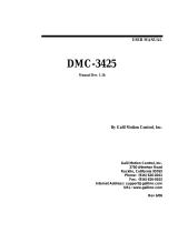
DMC-13X8 Functional Elements
The DMC-13X8 circuitry can be divided into the following functional groups as shown in Figure 1.1
and discussed below.

USER MANUAL Chapter 1 Overview • 11
WATCHDOG TIMER
68331
MICROCOMPUTER
WITH
2 Meg RAM
2 Meg FLASH EEPROM
HIGH-SPEED
MOTOR/ENCODER
INTERFACE
FOR
X,Y,Z,W
I/O INTERFACE
2ND FIFO
Primary
FIFO
INTERRUPTS
USER INTERFACE
8 UNCOMMITTED
ANALOG INPUTS
HIGH-SPEED LATCH FOR EACH AXIS
8 PROGRAMMABLE,
OPTOISOLATED
INPUTS
8 PROGRAMMABLE
OUTPUTS
ISOLATED LIMITS AND
HOME INPUTS
MAIN ENCODERS
AUXILIARY ENCODERS
+/- 10 VOLT OUTPUT FOR
SERVO MOTORS
PULSE/DIRECTION OUTPUT
FOR STEP MOTORS
HIGH SPEED ENCODER
COMPARE OUTPUT
VME HOST
Figure 1.1 - DMC-13X8 Functional Elements
Microcomputer Section
The main processing unit of the controller is a specialized 32-bit Motorola 68331 Series
Microcomputer with 2M RAM and 2M Flash EEPROM. The RAM provides memory for variables,
array elements, and application programs. The flash EEPROM provides non-volatile storage of
variables, programs, and arrays. It also contains the firmware of the controller.
Motor Interface
Galil’s GL-1800 custom, sub-micron gate array performs quadrature decoding of each encoder at up to
12 MHz. For standard servo operation, the controller generates a +/-10 Volt analog signal (16 Bit
DAC). For sinusoidal commutation operation, the controller uses 2 DACs to generate 2 +/-10Volt
analog signals. For stepper motor operation the controller generates a step and direction signal.
Communication
The DMC-13X8 is an A16D08(O) 6U VME card. The communication interface with the VME host
contains a primary and secondary communication channel. The primary channel uses a bi-directional
FIFO (AM4701). The secondary channel is a 512 byte Polling FIFO (IDT7201) where data is placed
into the controller’s FIFO buffer. The DMC-13X8 uses vectored hardware interrupts through the
VME host.
General I/O
The controller provides interface circuitry for 8 bi-directional, optoisolated inputs, 8 TTL outputs, and
8 analog inputs with 12-Bit ADC (16-bit optional). The general inputs can also be used for triggering a
high-speed positional latch for each axis.

Chapter 1 Overview • 12 USER MANUAL
The DMC-13X8 also provides standard 64 extended I/O points. These TTL I/O points are software
configurable in banks of 8 points, and can be brought out directly on the IOM-1964 I/O module.
Each axis on the controller has 2 encoders, the main encoder and an auxiliary encoder. Each unused
auxiliary encoder provides 2 additional inputs available for general use (except when configured for
stepper motor operation).
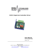
System Elements
As shown in Fig. 1.2, the DMC-13X8 is part of a motion control system which includes amplifiers,
motors, and encoders. These elements are described below.
Computer
DMC-1700/1800
Controller
Driver
Power Supply
Encoder Motor
Figure 1.2 - Elements of Servo systems
Motor
A motor converts current into torque which produces motion. Each axis of motion requires a motor
sized properly to move the load at the required speed and acceleration. (Galil's "Motion Component
Selector" software can help you with motor sizing). Contact Galil at 800-377-6329 if you would like
this product.
The motor may be a step or servo motor and can be brush-type or brushless, rotary or linear. For step
motors, the controller can operate full-step, half-step, or microstep drives. An encoder is not required
when step motors are used.
Amplifier (Driver)
For each axis, the power amplifier converts a +/-10 Volt signal from the controller into current to
drive the motor. For stepper motors, the amplifier converts step and direction signals into current.
The amplifier should be sized properly to meet the power requirements of the motor. For brushless
motors, an amplifier that provides electronic commutation is required or the controller must be
configured to provide sinusoidal commutation. The amplifiers may be either pulse-width-modulated
(PWM) or linear. They may also be configured for operation with or without a tachometer. For
current amplifiers, the amplifier gain should be set such that a 10 Volt command generates the
maximum required current. For example, if the motor peak current is 10A, the amplifier gain should
be 1 A/V. For velocity mode amplifiers, 10 Volts should run the motor at the maximum speed.

USER MANUAL Chapter 1 Overview • 13
Encoder
An encoder translates motion into electrical pulses which are fed back into the controller. The DMC-
13X8 accepts feedback from either a rotary or linear encoder. Typical encoders provide two channels in
quadrature, known as CHA and CHB. This type of encoder is known as a quadrature encoder.
Quadrature encoders may be either single-ended (CHA and CHB) or differential (CHA, CHA-, CHB,
CHB-). The controller decodes either type into quadrature states or four times the number of cycles.
Encoders may also have a third channel (or index) for synchronization.
The DMC-13X8 can also interface to encoders with pulse and direction signals.
There is no limit on encoder line density; however, the input frequency to the controller must not
exceed 3,000,000 full encoder cycles/second (12,000,000 quadrature counts/sec). For example, if the
encoder line density is 10,000 cycles per inch, the maximum speed is 300 inches/second. If higher
encoder frequency is required, please consult the factory.
The standard voltage level is TTL (zero to five volts), however, voltage levels up to 12 Volts are
acceptable. (If using differential signals, 12 Volts can be input directly to the DMC-13X8. Single-
ended 12 Volt signals require a bias voltage input to the complementary inputs).
The DMC-13X8 can accept analog feedback instead of an encoder for any axis. For more information
see the command AF in the command reference.
To interface with other types of position sensors such as resolvers or absolute encoders, Galil can
customize the controller and command set. Please contact Galil to talk to one of our applications
engineers about your particular system requirements.
Watch Dog Timer
The DMC-13X8 provides an internal watchdog timer which checks for proper microprocessor
operation. The timer toggles the Amplifier Enable Output (AEN), which can be used to switch the
amplifiers off in the event of a serious controller failure. The AEN output is normally high. During
power-up and if the microprocessor ceases to function properly, the AEN output will go low. The
error light for each axis will also turn on at this stage. A reset is required to restore the controller to
normal operation. Consult the factory for a Return Materials Authorization (RMA) Number if your
DMC-13X8 is damaged.

Chapter 1 Overview • 14 USER MANUAL
THIS PAGE LEFT BLANK INTENTIONALLY

USER MANUAL Chapter 2 Getting Started • 15
Chapter 2 Getting Started
The DMC-13X8 Motion Controller
Figure 2-1 - Outline of the DMC-13X8

Chapter 2 Getting Started • 16 USER MANUAL
1 Flash EEPROM J6 VME Connector
2 RAM JP1 Master Reset & UPGRD jumpers
3 Motorola 68331 microprocessor JP3 INCOM & LSCOM jumpers. Used for
bypassing opto-isolation for the limit, home, and
abort switches and the digital inputs IN1 - IN8.
See section “Bypassing Opto-Isolation”, Chap3.
4 GL-1800 custom gate array JP5 Jumpers used for configuring stepper motor
operation on axes 1-4.
5 Error LED JP9 IRQ jumper. Interrupts may be set on IRQ 1–7.
J1 100-pin high density connector for axes 1-4.
(Part number Amp #2-178238-9)
JP10 Address jumpers. The base address of the
controller is FFF0. Address jumpers A4-A15
may be set as offsets to that address
J3 80 Pin high-density connector for 64
extended I/O points.
JP11 IAD1-IAD4 allows transfer of the IRQ between
the controller and host. This three bit binary
combination must be set equal to the IRQ line
chosen.
J5 26-pin header connector for the auxiliary
encoder cable. (Axes 1-4)
Note: Above schematics are for most current controller revision. For older revision boards, please refer to Appendix.
Elements You Need
Before you start, you must get all the necessary system elements. These include:
1. DMC-13X8, (1) 100-pin cable and (1) ICM-1900. Connection to the extended I/O can be
made through the IOM-1964 opto-isolation module. Using the IOM-1964 requires (1)
IOM-1964, (1) CB-50-100 and (1) 100 pin cable.
2. Servo motors with Optical Encoder (one per axis) or step motors.
3. Power Amplifiers.
4. Power Supply for Amplifiers.
5. VME host and user interface.
The motors may be servo (brush type or brushless) or steppers. The amplifiers should be suitable for
the motor and may be linear or pulse-width-modulated. An amplifier may have current feedback,
voltage feedback or velocity feedback.
For servo motors in current mode, the amplifiers should accept an analog signal in the +/-10 Volt range
as a command. The amplifier gain should be set such that a +10V command will generate the
maximum required current. For example, if the motor peak current is 10A, the amplifier gain should
be 1 A/V. For velocity mode amplifiers, a command signal of 10 Volts should run the motor at the
maximum required speed. Set the velocity gain so that an input signal of 10V, runs the motor at the
maximum required speed.
For step motors, the amplifiers should accept step and direction signals. For start-up of a step motor
system refer to Step 7c “Connecting Step Motors”.

USER MANUAL Chapter 2 Getting Started • 17
Installing the DMC-13X8
Installation of a complete, operational DMC-13X8 system consists of 8 steps.
Step 1. Determine overall motor configuration.
Step 2. Install Jumpers on the DMC-13X8.
Step 3. Install the DMC-13X8 in the PC.
Step 4. Establish communications with the Galil controller.
Step 5. Determine the Axes to be used for sinusoidal commutation.
Step 6. Make connections to amplifier and encoder.
Step 7a. Connect standard servo motors.
Step 7b. Connect sinusoidal commutation motors.
Step 7c. Connect step motors.
Step 8. Tune the servo system.
Step 1. Determine Overall Motor Configuration
Before setting up the motion control system, the user must determine the desired motor configuration.
The DMC-13X8 can control any combination of standard servo motors, sinusoidally commutated
brushless motors, and stepper motors. Other types of actuators, such as hydraulics can also be
controlled. Please consult Galil for more information.
The following configuration information is necessary to determine the proper motor configuration:
Standard Servo Motor Operation:
The DMC-13X8 has been setup by the factory for standard servo motor operation providing an analog
command signal of +/- 10V. No hardware or software configuration is required for standard servo
motor operation.
Sinusoidal Commutation:
Sinusoidal commutation is configured through a single software command, BA. This configuration
causes the controller to reconfigure the number of available control axes.
Each sinusoidally commutated motor requires two DAC's. In standard servo operation, the DMC-
13X8 has one DAC per axis. In order to have the additional DAC for sinusoidal commutation, the
controller must be designated as having one additional axis for each sinusoidal commutation axis. For
example, to control two standard servo axes and one axis of sinusoidal commutation, the controller
will require a total of four DAC's and the controller must be a DMC-1348.
Sinusoidal commutation is configured with the command, BA. For example, BAX sets the X axis to
be sinusoidally commutated. The second DAC for the sinusoidal signal will be the highest available
DAC on the controller. For example: Using a DMC-1348, the command BAX will configure the X
axis to be the main sinusoidal signal and the 'W' axis to be the second sinusoidal signal.
The BA command also reconfigures the controller to indicate that the controller has one less axis of
'standard' control for each axis of sinusoidal commutation. For example, if the command BAX is
given to a DMC-1348 controller, the controller will be re-configured to a DMC-1338 controller. By
definition, a DMC-1338 controls 3 axes: X,Y and Z. The 'W' axis is no longer available since the
output DAC is being used for sinusoidal commutation.
Further instruction for sinusoidal commutation connections are discussed in Step 5.

Chapter 2 Getting Started • 18 USER MANUAL
Stepper Motor Operation:
To configure the DMC-13X8 for stepper motor operation, the controller requires a jumper for each
stepper motor and the command, MT, must be given. The installation of the stepper motor jumper is
discussed in the following section entitled "Installing Jumpers on the DMC-13X8". Further
instruction for stepper motor connections are discussed in Step 7c.
Step 2. Install Jumpers on the DMC-13X8
Address Jumpers
The DMC-13X8 resides in the 16-bit short I/O space of the VME system. The base address of the
DMC-13X8 is set at FFF0. The address jumpers at JP10 are used to select the specific address for the
DMC-13X8 in the VME system. Placing a jumper on an address A4 through A15 makes that location
a 0.
For example, to set the controller address to FFE0, a jumper is placed on location A4.
Master Reset and Upgrade Jumpers
JP1 contains two jumpers, MRST and UPGRD. The MRST jumper is the Master Reset jumper. With
MRST connected, the controller will perform a master reset upon PC power up or upon the reset input
going low. Whenever the controller has a master reset, all programs, arrays, variables, and motion
control parameters stored in EEPROM will be ERASED.
The UPGRD jumper enables the user to unconditionally update the controller’s firmware. This jumper
is not necessary for firmware updates when the controller is operating normally, but may be necessary
in cases of corrupted EEPROM. EEPROM corruption should never occur, however, it is possible if
there is a power fault during a firmware update. If EEPROM corruption occurs, your controller may
not operate properly. In this case, install the UPGRD Jumper and use the update firmware function on
the Galil Terminal to re-load the system firmware.
Opto Isolation Jumpers
The inputs and limit switches are optoisolated. If you are not using an isolated supply, the internal
+5V supply from the PC may be used to power the optoisolators. This is done by installing jumpers on
JP3.
Stepper Motor Jumpers
For each axis that will be used for stepper motor operation, the corresponding stepper mode (SM)
jumper must be connected. The stepper motor jumpers, labeled JP5, are located directly beside the
GL-1800 IC on the main board (see the diagram for the DMC-13X8). The individual jumpers are
labeled SMX, SMY, SMZ and SMW.
Hardware IRQ (Interrupt) Jumpers
The DMC-13X8 controller supports vectored hardware interrupts. The jumper locations JP9 and JP11
are used to select the IRQ line which will interrupt the bus. IRQ1 through IRQ7 are available to the
user as hardware interrupts, and are set at location JP9. The second set of jumpers located at JP11 are
labeled IAD4, IAD2 and IAD1. The summation of these jumpers should be set equal to the IRQ
selected on JP9.
For example, suppose the VME host for a certain system requires a hardware interrupt on IRQ 5. A
jumper would therefore be placed at location JP9 on the pins labeled IRQ5. In addition, IAD4 and
IAD1, which add up to 5, will be jumpered at location JP11.
The vector and the conditions triggering the hardware interrupt on the DMC-13X8 are set through
software using the EI or the UI command. The DMC-13X8 will provide the hardware interrupt to the

USER MANUAL Chapter 2 Getting Started • 19
system upon the specified conditions. It is up to the user to supply an appropriate interrupt handling
routine for the VME host.
(Optional) Motor Off Jumpers
The state of the motor upon power up may be selected with the placement of a hardware jumper on the
controller. With a jumper installed at the OPT location, the controller will be powered up in the ‘motor
off’ state. The SH command will need to be issued in order for the motor to be enabled. With no
jumper installed, the controller will immediately enable the motor upon power up. The MO command
will need to be issued to turn the motor off.
The OPT jumper is always located on the same block of jumpers as the stepper motor jumpers (SM).
This feature is only available to newer revision controllers. Please consult Galil for adding this
functionality to older revision controllers.
Step 3. Install the DMC-13X8 in the VME Host
The DMC-13X8 is installed directly into the VME bus. The procedure is outlined below.
Step A. Make sure the VME host is in the power-off condition.
Step B. Insert DMC-13X8 card into a slot in the VME bus.
Step E. Attach 100-pin cable to your controller card. If you are using a Galil ICM-1900 or
AMP-19X0, this cable connects into the J2 connection on the interconnect module. If
you are not using a Galil interconnect module, you will need to appropriately terminate
the cable to your system components, see the appendix for cable pin outs. The auxiliary
encoder connections are accessed through the 36-pin high-density connector, which will
mate via the CB-36-25 to the ICM-1900.
Step 4. Establish Communication with the Galil controller
The customer will be required to provide a communication interface for the DMC-13X8 and their
specified host VME system. For development of the software interface, refer to Chapter 4 to find
information on the communication registers of the controller.
NOTE: It is highly recommended that communication be established with the controller prior to
applying any power to the amplifiers or other components.
Step 5. Determine the Axes to be Used for Sinusoidal Commutation
* This step is only required when the controller will be used to control a brushless motor(s) with
sinusoidal commutation.
The command, BA is used to select the axes of sinusoidal commutation. For example, BAXZ sets X
and Z as axes with sinusoidal commutation.
Notes on Configuring Sinusoidal Commutation:
The command, BA, reconfigures the controller such that it has one less axis of 'standard' control for
each axis of sinusoidal commutation. For example, if the command BAX is given to a DMC-1338
controller, the controller will be re-configured to be a DMC-1328 controller. In this case the highest
axis is no longer available except to be used for the 2
nd
phase of the sinusoidal commutation. Note that
the highest axis on a controller can never be configured for sinusoidal commutation.
The first phase signal is the motor command signal. The second phase is derived from the highest
DAC on the controller. When more than one axis is configured for sinusoidal commutation, the
highest sinusoidal commutation axis will be assigned to the highest DAC and the lowest sinusoidal
commutation axis will be assigned to the lowest available DAC. Note the lowest axis is the X axis.

Chapter 2 Getting Started • 20 USER MANUAL
Example: Sinusoidal Commutation Configuration using a DMC-1348
BAXZ
This command causes the controller to be reconfigured as a DMC-1328 controller. The X and Z axes
are configured for sinusoidal commutation. The first phase of the X axis will be the motor command
X signal. The second phase of the X axis will be Y signal. The first phase of the Z axis will be the
motor command Z signal. The second phase of the Z axis will be the motor command W signal.
Step 6. Make Connections to Amplifier and Encoder.
Once you have established communications between the software and the DMC-13X8, you are ready
to connect the rest of the motion control system. The motion control system typically consists of an
ICM-1900 Interface Module, an amplifier for each axis of motion, and a motor to transform the current
from the amplifier into torque for motion. Galil also offers the AMP-19X0 series Interface Modules
which are ICM-1900’s equipped with servo amplifiers for brush type DC motors.
If you are using an ICM-1900, connect the 100-pin high-density cable to the DMC-13X8 and to the
connector located on the AMP-19x0 or ICM-1900 board. The ICM-1900 provides screw terminals for
access to the connections described in the following discussion.
System connection procedures will depend on system components and motor types. Any combination
of motor types can be used with the DMC-13X8. If sinusoidal commutation is to be used, special
attention must be paid to the reconfiguration of axes.
Here are the first steps for connecting a motion control system:
Step A. Connect the motor to the amplifier with no connection to the controller. Consult the
amplifier documentation for instructions regarding proper connections. Connect and
turn-on the amplifier power supply. If the amplifiers are operating properly, the motor
should stand still even when the amplifiers are powered up.
Step B. Connect the amplifier enable signal.
Before making any connections from the amplifier to the controller, you need to verify
that the ground level of the amplifier is either floating or at the same potential as earth.
WARNING: When the amplifier ground is not isolated from the power line or when it has a different potential
than that of the computer ground, serious damage may result to the computer controller and amplifier.
If you are not sure about the potential of the ground levels, connect the two ground
signals (amplifier ground and earth) by a 10 KΩ resistor and measure the voltage across
the resistor. Only if the voltage is zero, connect the two ground signals directly.
The amplifier enable signal is used by the controller to disable the motor. This signal is
labeled AMPENX for the X axis on the ICM-1900 and should be connected to the enable
signal on the amplifier. Note that many amplifiers designate this signal as the INHIBIT
signal. Use the command, MO, to disable the motor amplifiers - check to insure that the
motor amplifiers have been disabled (often this is indicated by an LED on the amplifier).
This signal changes under the following conditions: the watchdog timer activates, the
motor-off command, MO, is given, or the OE1 command (Enable Off-On-Error) is given
and the position error exceeds the error limit. As shown in Figure 3-3, AEN can be used
to disable the amplifier for these conditions.
The standard configuration of the AEN signal is TTL active high. In other words, the
AEN signal will be high when the controller expects the amplifier to be enabled. The
polarity and the amplitude can be changed if you are using the ICM-1900 interface board.
To change the polarity from active high (5 volts = enable, zero volts = disable) to active
low (zero volts = enable, 5 volts = disable), replace the 7407 IC with a 7406. Note that
many amplifiers designate the enable input as ‘inhibit’.
/