
USER MANUAL
DMC-3425
Manual Rev. 1.1b
By Galil Motion Control, Inc.
Galil Motion Control, Inc.
3750 Atherton Road
Rocklin, California 95765
Phone: (916) 626-0101
Fax: (916) 626-0102
Internet Address: [email protected]
URL: www.galilmc.com
Rev 6/06


DMC-3425 Contents • i
Contents
Contents i
Chapter 1 Overview 1
Introduction ...............................................................................................................................1
Overview of Motor Types..........................................................................................................2
Standard Servo Motors with +/- 10 Volt Command Signal.........................................2
Stepper Motor with Step and Direction Signals ..........................................................2
Brushless Servo Motor with Sinusoidal Commutation................................................ 2
DMC-3425 Functional Elements ............................................................................................... 4
Microcomputer Section ...............................................................................................4
Motor Interface............................................................................................................4
Communication ...........................................................................................................4
General I/O..................................................................................................................5
System Elements .........................................................................................................5
Motor...........................................................................................................................5
Amplifier (Driver) ....................................................................................................... 5
Encoder........................................................................................................................6
Watch Dog Timer........................................................................................................6
Chapter 2 Getting Started 7
The DMC-3425 Motion Controller............................................................................................ 7
Elements You Need ................................................................................................................... 8
Installing the DMC-3425 Controller..........................................................................................8
Step 1. Determine Overall Motor Configuration........................................................ 9
Step 2. Configuring Jumpers on the DMC-3425 .........................................................9
Step 3. Connecting AC or DC power and the Serial Cable to the DMC-3425.......... 11
Step 4. Installing the Communications Software.......................................................12
Step 5. Establishing Communication between the DMC-3425 and the host PC .......12
Step 6. Set-up axis for sinusoidal commutation (optional)....................................... 17
Step 7. Make connections to amplifier and encoder..................................................17
Step 8a. Connect Standard Servo Motor...................................................................19
Step 8b. Connect brushless motor for sinusoidal commutation................................23
Step 8c. Connect Step Motors ...................................................................................26
Step 9. Tune the Servo System.................................................................................. 27
Step 10. Configure the Distributed Control System ..................................................28
Design Examples ..................................................................................................................... 32
Example 1 - System Set-up ....................................................................................... 32
Example 2 - Profiled Move .......................................................................................32
Example 3 - Position Interrogation............................................................................32
Example 4 - Absolute Position .................................................................................. 32

ii • Contents DMC-3425
Example 5 - Velocity Control (Jogging) ...................................................................33
Example 6 - Operation Under Torque Limit .............................................................33
Example 7 - Interrogation..........................................................................................33
Example 8 - Operation in the Buffer Mode ...............................................................33
Example 9 - Motion Programs...................................................................................34
Example 10 - Motion Programs with Loops..............................................................34
Example 11- Motion Programs with Trippoints........................................................ 34
Example 12 - Control Variables ................................................................................35
Example 13 - Control Variables and Offset .............................................................. 35
Chapter 3 Connecting Hardware 37
Overview .................................................................................................................................37
Using Inputs.............................................................................................................................37
Limit Switch Input.....................................................................................................37
Home Switch Input....................................................................................................38
Abort Input ................................................................................................................38
Uncommitted Digital Inputs ...................................................................................... 39
Amplifier Interface ..................................................................................................................39
TTL Inputs...............................................................................................................................40
Analog Inputs ..........................................................................................................................40
TTL Outputs ............................................................................................................................41
Chapter 4 Communication 43
Introduction .............................................................................................................................43
RS232 Port...............................................................................................................................43
RS232 - Port 1 DATATERM ................................................................................43
RS-232 Configuration ............................................................................................... 43
Ethernet Configuration ............................................................................................................ 44
Communication Protocols .........................................................................................44
Addressing.................................................................................................................44
Ethernet Handles .......................................................................................................45
Global vs. Local Operation........................................................................................45
Operation of Distributed Control...............................................................................47
Accessing the I/O of the Slaves.................................................................................47
Handling Communication Errors...............................................................................48
Multicasting............................................................................................................... 48
Unsolicited Message Handling..................................................................................49
IOC-7007 Support .....................................................................................................49
Modbus Support ........................................................................................................50
Other Communication Options.................................................................................. 51
Data Record .............................................................................................................................52
Data Record Map....................................................................................................... 52
Explanation of Status Information and Axis Switch Information..............................55
Notes Regarding Velocity and Torque Information ..................................................56
QZ Command ............................................................................................................56
Using Third Party Software....................................................................................... 57
Chapter 5 Command Basics 59
Introduction .............................................................................................................................59
Command Syntax - ASCII.......................................................................................................59
Coordinated Motion with more than 1 axis ............................................................... 60
Command Syntax - Binary ......................................................................................................60
Binary Command Format .......................................................................................... 61
Binary command table...............................................................................................62

DMC-3425 Contents• iii
Controller Response to DATA ................................................................................................63
Interrogating the Controller .....................................................................................................64
Interrogation Commands...........................................................................................64
Summary of Interrogation Commands ...................................................................... 64
Interrogating Current Commanded Values................................................................ 64
Operands....................................................................................................................64
Command Summary.................................................................................................. 65
Chapter 6 Programming Motion 67
Overview .................................................................................................................................67
Global vs. Local Operation........................................................................................67
Independent Axis Positioning..................................................................................................69
Command Summary - Independent Axis ..................................................................70
Operand Summary - Independent Axis .....................................................................70
Examples ................................................................................................................... 70
Independent Jogging................................................................................................................ 72
Command Summary - Jogging.................................................................................. 72
Operand Summary - Independent Axis .....................................................................72
Examples ................................................................................................................... 72
Linear Interpolation Mode (Local Mode) ................................................................................73
Specifying Linear Segments......................................................................................73
Additional Commands...............................................................................................74
Command Summary - Linear Interpolation...............................................................75
Operand Summary - Linear Interpolation..................................................................75
Example.....................................................................................................................76
Example - Linear Move.............................................................................................76
Example - Multiple Moves........................................................................................ 77
Vector Mode: Linear and Circular Interpolation (Local Mode) ..............................................78
Specifying Vector Segments ..................................................................................... 78
Additional commands................................................................................................ 79
Command Summary - Coordinated Motion Sequence .............................................. 80
Operand Summary - Coordinated Motion Sequence.................................................80
Electronic Gearing (Local Mode) ............................................................................................ 82
Command Summary - Electronic Gearing ................................................................82
Electronic Cam (Local Mode) ................................................................................................. 83
Contour Mode (Local Mode)...................................................................................................89
Specifying Contour Segments ................................................................................... 89
Additional Commands...............................................................................................91
Command Summary - Contour Mode .......................................................................91
Operand Summary - Contour Mode .......................................................................... 91
Virtual Axis (Local Mode) ...................................................................................................... 94
Ecam Master Example............................................................................................... 95
Sinusoidal Motion Example ......................................................................................95
Stepper Motor Operation ......................................................................................................... 95
Specifying Stepper Motor Operation.........................................................................95
Stepper Motor Smoothing ......................................................................................... 96
Monitoring Generated Pulses vs. Commanded Pulses ..............................................96
Motion Complete Trippoint.......................................................................................97
Using an Encoder with Stepper Motors.....................................................................97
Command Summary - Stepper Motor Operation....................................................... 97
Operand Summary - Stepper Motor Operation..........................................................97
Dual Loop (Auxiliary Encoder)...............................................................................................98
Using the CE Command............................................................................................98
Additional Commands for the Auxiliary Encoder.....................................................98
Backlash Compensation ............................................................................................ 98

iv • Contents DMC-3425
Example.....................................................................................................................99
Motion Smoothing................................................................................................................. 100
Using the IT and VT Commands:............................................................................100
Example...................................................................................................................100
Homing .................................................................................................................................. 101
Example...................................................................................................................102
Command Summary - Homing Operation............................................................... 104
Operand Summary - Homing Operation..................................................................104
High Speed Position Capture (Latch) ....................................................................................104
Example...................................................................................................................105
Chapter 7 Application Programming 107
Overview ...............................................................................................................................107
Global vs. Local Programming................................................................................ 107
Entering Programs ................................................................................................................. 108
Edit Mode Commands............................................................................................. 108
Example:.................................................................................................................. 109
Program Format..................................................................................................................... 109
Using Labels in Programs .......................................................................................109
Special Labels..........................................................................................................110
Commenting Programs............................................................................................110
Executing Programs - Multitasking ....................................................................................... 111
Debugging Programs .............................................................................................................112
Trace Command ...................................................................................................... 113
Error Code Command..............................................................................................113
Stop Code Command...............................................................................................113
RAM Memory Interrogation Commands ................................................................ 113
Operands..................................................................................................................114
Breakpoints and single stepping..............................................................................114
EEPROM Memory Interrogation Operands ............................................................ 114
Program Flow Commands ..................................................................................................... 115
Event Triggers & Trippoints....................................................................................115
Conditional Jumps...................................................................................................119
If, Else, and Endif.................................................................................................... 121
Subroutines.............................................................................................................. 123
Stack Manipulation..................................................................................................123
Auto-Start and Auto Error Routine .........................................................................123
Automatic Subroutines for Monitoring Conditions................................................. 124
Mathematical and Functional Expressions ............................................................................127
Mathematical Operators .......................................................................................... 127
Bit-Wise Operators.................................................................................................. 128
Functions ................................................................................................................. 129
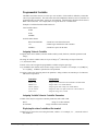
Variables................................................................................................................................129
Programmable Variables ......................................................................................... 130
Operands................................................................................................................................ 131
Special Operands.....................................................................................................131
Examples ................................................................................................................. 132
Arrays .................................................................................................................................... 132
Defining Arrays.......................................................................................................132
Assignment of Array Entries ................................................................................... 132
Uploading and Downloading Arrays to On Board Memory....................................133
Automatic Data Capture into Arrays.......................................................................133
Deallocating Array Space........................................................................................ 135
Outputting Numbers and Strings ........................................................................................... 135
Sending Messages ................................................................................................... 135

DMC-3425 Contents• v
Displaying Variables and Arrays............................................................................. 137
Interrogation Commands.........................................................................................137
Formatting Variables and Array Elements .............................................................. 139
Converting to User Units......................................................................................... 140
Hardware I/O .........................................................................................................................140
Digital Outputs ........................................................................................................140
Digital Inputs...........................................................................................................141
Input Interrupt Function ..........................................................................................142
Analog Inputs .......................................................................................................... 142
Extended I/O of the DMC-3425 Controller ........................................................................... 143
Configuring the I/O of the DMC-3425.................................................................... 143
Saving the State of the Outputs in Non-Volatile Memory....................................... 144
Accessing Extended I/O .......................................................................................... 144
Interfacing to Grayhill or OPTO-22 G4PB24 .........................................................145
Example Applications............................................................................................................145
Wire Cutter.............................................................................................................. 145
A-B (X-Y) Table Controller....................................................................................146
Speed Control by Joystick....................................................................................... 148
Position Control by Joystick....................................................................................149
Chapter 8 Hardware & Software Protection 151
Introduction ...........................................................................................................................151
Hardware Protection .............................................................................................................. 151
Output Protection Lines........................................................................................... 151
Input Protection Lines .............................................................................................152
Software Protection ...............................................................................................................152
Example:.................................................................................................................. 152
Programmable Position Limits ................................................................................ 152
Example:.................................................................................................................. 153
Off-On-Error ........................................................................................................... 153
Examples: ................................................................................................................ 153
Automatic Error Routine ......................................................................................... 153
Example:.................................................................................................................. 153
Limit Switch Routine .............................................................................................. 154
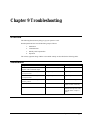
Chapter 9 Troubleshooting 155
Overview ...............................................................................................................................155
Installation .............................................................................................................................155
Communication......................................................................................................................156
Stability..................................................................................................................................156
Operation ...............................................................................................................................156
Chapter 10 Theory of Operation 157
Overview ...............................................................................................................................157
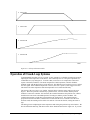
Operation of Closed-Loop Systems....................................................................................... 159
System Modeling................................................................................................................... 160
Motor-Amplifier......................................................................................................161
Encoder....................................................................................................................163
DAC ........................................................................................................................ 164
Digital Filter ............................................................................................................164
ZOH.........................................................................................................................165
System Analysis.....................................................................................................................165
System Design and Compensation.........................................................................................167
The Analytical Method............................................................................................ 167

vi • Contents DMC-3425
Appendices 171
Electrical Specifications ........................................................................................................171
Servo Control .......................................................................................................... 171
Input/Output ............................................................................................................171
Power Requirements................................................................................................ 171
Performance Specifications ................................................................................................... 171
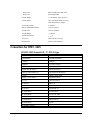
Connectors for DMC-3425 .................................................................................................... 172
J3 DMC-3425 General I/O; 37- PIN D-type ........................................................... 172
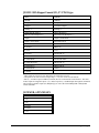
J3 DMC-3425-Stepper General I/O; 37- PIN D-type.............................................. 173
J5 POWER; 6 PIN MOLEX.................................................................................... 173
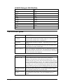
J1 RS232 Main port: DB-9 Pin Male: ..................................................................... 174
Pin-Out Description............................................................................................................... 174
ICM-1460 Interconnect Module ............................................................................................ 175
Opto-Isolation Option for ICM-1460.....................................................................................177
Opto-isolated inputs: ............................................................................................... 177
Opto-isolated outputs: ............................................................................................. 178
64 Extended I/O of the DMC-3425 Controller ...................................................................... 179
Configuring the I/O of the DMC-3425 with DB-14064 .......................................... 179
Connector Description:............................................................................................ 181
IOM-1964 Opto-Isolation Module for Extended I/O Controllers.......................................... 183
Description: .............................................................................................................183
Overview .................................................................................................................184
Configuring Hardware Banks.................................................................................. 185
Digital Inputs...........................................................................................................185
High Power Digital Outputs .................................................................................... 187
Standard Digital Outputs ......................................................................................... 188
Electrical Specifications .......................................................................................... 189
Relevant DMC Commands...................................................................................... 190
Screw Terminal Listing ........................................................................................... 190
Coordinated Motion - Mathematical Analysis....................................................................... 193
List of Other Publications...................................................................................................... 196
Training Seminars.................................................................................................................. 196
Contacting Us ........................................................................................................................197
WARRANTY ........................................................................................................................ 198
Index 199

DMC-3425 Chapter 1 Overview• 1
Chapter 1 Overview
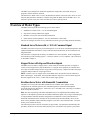
Introduction
The DMC-3425 provides a highly versatile, powerful form of distributed control where multiple DMC-
3425 controllers can be linked together on the Ethernet. One DMC-3425 is designated as a “master”
that receives all commands from the host computer and passes them to the other “slave” DMC-3425
controllers. Efficient, quick communications are realized as this approach eliminates the usual,
multiple communication links between the host computer and each controller.
Each DMC-3425 precisely controls two servo motors, providing ECAM, gearing and both linear and
circular interpolation for coordinated motion along the two local axis. A single axis DMC-3415 is also
available. When acting as the “master,” a DMC-3425 can receive PR, PA and JG commands for up to
eight axes and distribute them to the appropriate controller. Coordinated motion is commanded locally
by each DMC-3425 “slave” controller. Performance capability of these controllers includes: 12 MHz
encoder input frequency, 16-bit motor command output DAC, +/-2 billion counts total travel per move,
250 μsec minimum sample rate and non-volatile memory for program and parameter storage.
Designed for maximum flexibility, the DMC-3425 can be interfaced to a variety of motors and drives
including step motors, brush and brushless servo motors and hydraulics. The DMC-3425 can also be
configured to provide sinusoidal commutation for brushless motors.
The controller accepts feedback from a quadrature linear or rotary encoder with input frequencies up to
12 million quadrature counts per second. Modes of motion include jogging, point-to-point positioning,
electronic cam, electronic gearing and contouring. Several motion parameters can be specified
including acceleration and deceleration rates and slew speed. The DMC-3425 also provides motion
smoothing to eliminate jerk.
For synchronization with outside events, the DMC-3425 provides uncommitted I/O. The DMC-3425
provides up to 3 digital inputs, 3 digital outputs and 2 analog inputs. The DMC-3415 provides 7
digital inputs, 3 digital outputs and 2 analog inputs. Committed digital inputs are provided for forward
and reverse limits, abort, home, and definable input interrupts. An additional 64 configurable I/O
points may be added with the optional DB-14064 daughter card. The DMC-3425 distributed system
may also be linked with multiple IOC-7007 Ethernet I/O modules for complete machine I/O control.
Event triggers can automatically check for elapsed time, distance and motion complete.
The DMC-3425 is easy to program. Instructions are represented by two letter commands such as BG
for Begin and SP for Speed. Conditional instructions, Jump statements and arithmetic functions are
included for writing self-contained applications programs. An internal editor allows programs to be
quickly entered and edited, and support software such as the WSDK allows quick system set-up and
tuning. Commands may also be sent in Binary to decrease processing time.
To prevent system damage during machine operation, the DMC-3425 provides many error-handling
features. These include software and hardware limits, automatic shut-off on excessive error, abort
input and user-definable error and limit routines.

2 • Chapter 1 Overview DMC-3425
The DMC-3425 is designed for stand-alone applications and provides non-volatile storage for
programs, variables and array elements.
This manual uses ‘DMC-3425’ to refer to the distributed control E-series from Galil. However, most
functions described in this manual are available using either the DMC-3425 or the DMC-3415. If a
function is specific to only one of the controllers, this will be explicitly stated.
Overview of Motor Types
The DMC-3425 can provide the following types of motor control:
1. Standard servo motors with +/- 10 volt command signals
2. Step motors with step and direction signals
3. Brushless servo motors with sinusoidal commutation
4. Other actuators such as hydraulics - For more information, contact Galil.
The user can configure each axis for any combination of motor types, providing maximum flexibility.
Standard Servo Motors with +/- 10 Volt Command Signal
The DMC-3425 achieves superior precision through use of a 16-bit motor command output DAC and a
sophisticated PID filter that features velocity and acceleration feedforward, an extra notch filter and
integration limits.
The controller is configured by the factory for standard servo motor operation. In this configuration,
the controller provides an analog signal (+/- 10Volt) to connect to a servo amplifier. This connection
is described in Chapter 2.
Stepper Motor with Step and Direction Signals
The DMC-3425 can control 2 stepper motors. In this mode, the controller provides two signals to
connect to each stepper motor: Step and Direction. For stepper motor operation, the controller does
not require an encoder and operates the stepper motor in an open loop. Chapter 2 describes the proper
connection and procedure for using stepper motors.
NOTE: In order to use two stepper motors on the DMC-3425, the controller must be ordered as a
DMC-3425-Stepper. In this mode, the Amp Enable and Error outputs are converted to the Step and
Direction signals for the Y-axis. Contact Galil for other stepper options.
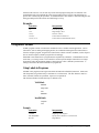
Brushless Servo Motor with Sinusoidal Commutation
The DMC-3415 can provide sinusoidal commutation for brushless motors (BLM). In this
configuration, the controller generates two sinusoidal signals for connection with amplifiers
specifically designed for this purpose. Please note, for a 2 axis DMC-3425, converting to a brushless
motor uses up the second axis.
Note: The task of generating sinusoidal commutation may be accomplished in the brushless motor
amplifier. If the amplifier generates the sinusoidal commutation signals, only a single command signal
is required and the controller should be configured for a standard servo motor (described above).
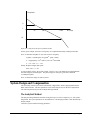
Sinusoidal commutation in the controller can be used with linear and rotary BLMs. However, the
motor velocity should be limited such that a magnetic cycle lasts at least 6 milliseconds*. For faster
motors, please contact the factory.
The controller provides a one-time, automatic set-up procedure. The parameters determined by this
procedure can then be saved in non-volatile memory to be used whenever the system is powered on.

DMC-3425 Chapter 1 Overview• 3
The DMC-3415 can control BLMs equipped with Hall sensors as well as without Hall sensors. If hall
sensors are available, once the controller has been setup, the controller will estimate the commutation
phase upon reset. This allows the motor to function immediately upon power up. The Hall effect
sensors also provide a method for setting the precise commutation phase. Chapter 2 describes the
proper connection and procedure for using sinusoidal commutation of brushless motors.
* 6 Milliseconds per magnetic cycle assumes a servo update of 1 msec (default rate).

4 • Chapter 1 Overview DMC-3425
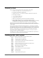
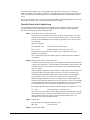
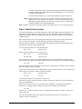
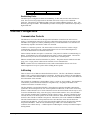
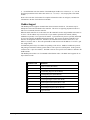
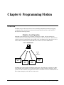
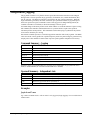
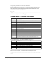
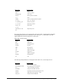
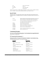
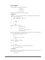
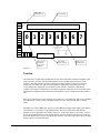
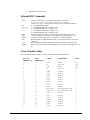
DMC-3425 Functional Elements
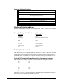
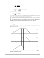
The DMC-3425 circuitry can be divided into the following functional groups as shown in Figure 1.1
and discussed below.
WATCHDOG TIMER
68331
MICROCOMPUTER
WITH
1 Meg RAM
4 Meg FLASH EEPROM
HIGH-SPEED
MOTOR/ENCODER
INTERFACE
I/O INTERFACE
ETHERNET
RS-232
2 UNCOMMITTED
ANALOG INPUTS
HIGH-SPEED LATCH FOR EACH AXIS
3 PROGRAMMABLE,
INPUTS
3 PROGRAMMABLE
OUTPUTS
ISOLATED LIMITS AND
HOME INPUTS
MAIN ENCODERS
AUXILIARY ENCODERS
+/- 10 VOLT OUTPUT FOR
SERVO MOTORS
PULSE/DIRECTION OUTPUT
FOR STEP MOTORS
HIGH SPEED ENCODER
COMPARE OUTPUT
Figure 1.1 - DMC-3425 Functional Elements
Microcomputer Section
The main processing unit of the DMC-3425 is a specialized 32-bit Motorola 68331 Series
Microcomputer with 1 Meg RAM and 4 Meg Flash EEPROM. The RAM provides memory for
variables, array elements and application programs. The flash EEPROM provides non-volatile storage
of variables, programs, and arrays. It also contains the DMC-3425 firmware.
Motor Interface
Galil’s GL-1800 custom, sub-micron gate array performs quadrature decoding of each encoder at up to
12 MHz. For standard servo operation, the controller generates a +/-10 Volt analog signal (16 Bit
DAC). For sinusoidal commutation operation, the controller uses two DACs to generate two +/-10Volt
analog signals. For stepper motor operation, the controller generates a step and direction signal.
Communication
The communication interface with the DMC-3425 consists of one RS-232 port (19.2 kbaud) and one
10base-T Ethernet port.

DMC-3425 Chapter 1 Overview• 5
General I/O
The DMC-3415 provides interface circuitry for 7 TTL inputs and 3 TTL outputs. In addition, the
controller provides two 12-bit analog inputs. The general inputs can also be used for triggering a high-
speed positional latch for each axis.
NOTE: In order to accommodate 2 axes on the DMC-3425, many of the general I/O features become
dedicated I/O for the second axis. The standard DMC-3425 will have 3 TTL inputs, 3 TTL outputs and
2 analog inputs. If extra I/O is needed, the DB-14064 I/O daughter card increases general purpose I/O
by 64 points.
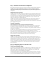
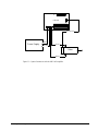
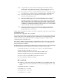
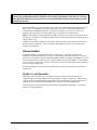
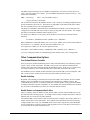
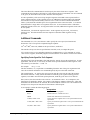
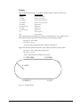
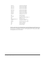
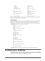
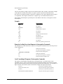
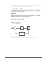
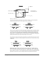
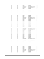
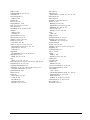
System Elements
As shown in Fig. 1.2, the DMC-3425 is part of a motion control system, which includes amplifiers,
motors and encoders. These elements are described below.
Computer DMC-3425 Controller
A
mplifier (Driver)
Power Supply
Encoder Motor
Figure 1.2 - Elements of Servo systems
Motor
A motor converts current into torque, which produces motion. Each axis of motion requires a motor
sized properly to move the load at the required speed and acceleration. (Galil's "Motion Component
Selector" software can help you with motor sizing). Contact Galil for more information.
The motor may be a step or servo motor and can be brush-type or brushless, rotary or linear. For step
motors, the controller is capable of controlling full-step, half-step, or microstep drives. An encoder is
not required when step motors are used.
Amplifier (Driver)
For each axis, the power amplifier converts a +/-10 Volt signal from the controller into current to drive
the motor. For stepper motors, the amplifier converts step and direction signals into current. The
amplifier should be sized properly to meet the power requirements of the motor. For brushless motors,
an amplifier that provides electronic commutation is required or the controller must be configured to
provide sinusoidal commutation. The amplifiers may be either pulse-width-modulated (PWM) or
linear. They may also be configured for operation with or without a tachometer. For current
amplifiers, the amplifier gain should be set such that a 10 Volt command generates the maximum
required current. For example, if the peak motor current is 10A, the amplifier gain should be 1 A/V.
For velocity mode amplifiers, 10 Volts should run the motor at the maximum speed.

6 • Chapter 1 Overview DMC-3425
For step motors, the amplifiers should accept step and direction signals.
Encoder
An encoder translates motion into electrical pulses that are fed back into the controller. The DMC-3425
accepts feedback from either a rotary or linear encoder. Typical encoders provide two channels in
quadrature, known as CHA and CHB. This type of encoder is known as a quadrature encoder.
Quadrature encoders may be either single-ended (CHA and CHB) or differential (CHA,CHA-,
CHB,CHB-). The DMC-3425 decodes either type into quadrature states or four times the number of
cycles. Encoders may also have a third channel (or index) for synchronization. The DMC-3425 can
also interface to encoders with pulse and direction signals.
There is no limit on encoder line density; however, the input frequency to the controller must not
exceed 3,000,000 full encoder cycles/second (12,000,000 quadrature counts/sec). For example, if the
encoder line density is 10000 cycles per inch, the maximum speed is 300 inches/second. If higher
encoder frequency is required, please consult the factory.
The standard voltage level is TTL (zero to five volts), however, voltage levels up to 12 Volts are
acceptable. (If using differential signals, 12 Volts can be input directly to the DMC-3425. Single-
ended 12 Volt signals require a bias voltage input to the complementary inputs.)
The DMC-3425 can accept analog feedback instead of an encoder for any axis. For more information
see description of analog feedback in the Command Reference under the AF command.
To interface with other types of position sensors such as resolvers or absolute encoders, Galil can
customize the controller and command set. Please contact Galil to talk to one of our applications
engineers about your particular system requirements.
Watch Dog Timer
The DMC-3425 provides an internal watch dog timer which checks for proper microprocessor
operation. The timer toggles the Amplifier Enable Output (AEN), which can be used to switch the
amplifiers off in the event of a serious DMC-3425 failure. The AEN output is normally high. During
power-up and if the microprocessor ceases to function properly, the AEN output will go low. The
error light for each axis will also turn on at this stage. A reset is required to restore the DMC-3425 to
normal operation. Consult the factory for a Return Materials Authorization (RMA) number if your
DMC-3425 is damaged.

DMC-3425 Chapter 2 Getting Started• 7
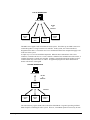
Chapter 2 Getting Started
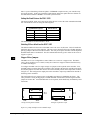
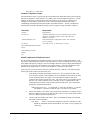
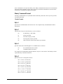
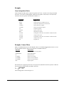
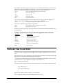
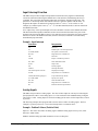
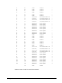
The DMC-3425 Motion Controller
DMC-1415
REV D
GALIL MOTION CONTROL
MADE IN USA
MO
SMX
SMY
*
MRST
UPGD
1200
9600
SD MC
A1
A2
A8
A4
J5
J6
J1
U2
SW1
J2
JP1
U10
U1
J3
D4
D2
JP3
J4
JP2
U4
Stepper motor/Motor off
configuration jumpers
Daughter card connector for
DB-14064 Extended I/O card
+12 +5 +5 G G -12
6 Pin Molex
Power Connector
Distributed Control Axis
configuration jumpers
Step/Direction or
Motor Command
configuration jumpers
GL-1800
Motorola
68331
Main 37-pin DSub
connector
Status/Communications
LED's
RJ-45 10BaseT
Ethernet connector
Reset switch
Master reset/baud
rate jumpers
9-Pin DSub
RS232 serial port
Ethernet
network IC
RAM
+12-12
+12V/-12V Test
Points
+5 G
+5V/Gnd Test
Points
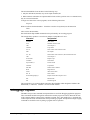
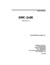
Figure 2.1 – Outline of the DMC-3425

8 • Chapter 2 Getting Started DMC-3425
Elements You Need
Before you start, you must get all the necessary system elements. These include:
1. (1) DMC-3425 or DMC-3415, (1) 37-pin cable (order Cable -37).
2. Servo motor(s) with encoders or stepper motors.
3. Appropriate motor drive - servo amp (Power Amplifier or AMP-1460) or stepper drive.
4. Power Supply for Amplifier
5. +5V, ±12V supply for DMC-3425
6. Communication CD from Galil
7. WSDK Servo Design Software (not necessary, but strongly recommended)
8. Interface Module ICM-1460 with screw-type terminals or integrated Interface
Module/Amplifier, AMP-1460. (Note: An interconnect module is not necessary, but strongly
recommended.) Also, the AMP-1460 only provides for 1 axis power amplification.
The motors may be servo (brush or brushless type) or steppers. The driver (amplifier) should be
suitable for the motor and may be linear or pulse-width-modulated and it may have current feedback or
voltage feedback.
For servo motors, the drivers should accept an analog signal in the +/-10 Volt range as a command.
The amplifier gain should be set so that a +10V command will generate the maximum required current.
For example, if the motor peak current is 10A, the amplifier gain should be 1 A/V. For velocity mode
amplifiers, a command signal of 10 Volts should run the motor at the maximum required speed.
For step motors, the driver should accept step and direction signals. For start-up of a step motor
system refer to Step 8c “Connecting Step Motors”.
The WSDK software is highly recommended for first time users of the DMC-3425. It provides step-
by-step instructions for system connection, tuning and analysis.
Installing the DMC-3425 Controller
Installation of a complete, operational DMC-3425 system consists of 9 steps.
Step 1. Determine overall motor configuration.
Step 2. Configuring jumpers on the DMC-3425.
Step 3. Connect the DC power supply and serial cable to the DMC-3425.
Step 4. Install the communications software.
Step 5. Establish communications between the DMC-3425 and the host PC.
Step 6. Set-up axis for sinusoidal commutation.
Step 7. Make connections to amplifier and encoder.
Step 8a. Connect standard servo motor.
Step 8b. Connect brushless motor for sinusoidal commutation.
Step 8c. Connect step motor.
Step 9. Tune servo system.
Step 10. Configure distributed control system.

DMC-3425 Chapter 2 Getting Started• 9
Step 1. Determine Overall Motor Configuration
Before setting up the motion control system, the user must determine the desired motor configuration.
The DMC-3425 can control standard brush or brushless servo motors, sinusoidally commutated
brushless motors or stepper motors. For control of other types of actuators, such as hydraulics, please
contact Galil. The following configuration information is necessary to determine the proper motor
configuration:
Standard Servo Motor Operation:
The DMC-3425 has been setup by the factory for standard servo motor operation providing an analog
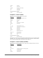
command signal of +/- 10 volt. The position of the jumpers at JP2/JP3 determines the type of output
the controllers will provide, analog motor command or PWM output. The installation of these jumpers
is discussed in the section “Configuring Jumpers on the DMC-3425”. Figure 2.2 shows how the
jumpers are configured for the standard output mode.
The DMC-3425 controller will output the analog command signal to either brush or brushless servo
amplifiers. Please note that if the brushless amplifier provides the sinusoidal commutation, the
standard servo motor operation from the controller will be used. If the commutation is to be performed
by the controller, please see below.
Sinusoidal Commutation:
Please consult the factory before operating with sinusoidal commutation.
Sinusoidal commutation is configured through a single software command, BA. This setting causes
the controller to reconfigure the control axis to output two commutated phases. The DMC-3425
requires two DAC outputs for a single axis of commutation. Issuing the BA command will enable the
second DAC for commutation.
If a DMC-3425 is used for sinusoidal commutation, the second axis will be used for the second DAC
phase. Please note that if the DMC-3425 is used for sinusoidal commutation, it will still be
represented by two axes within the distributed system, even though only one axis is truly active. The
DMC-3415 in brushless mode will take only a single axis within the distributed system.
Further instruction for sinusoidal commutation connections are discussed in Step 6.
Stepper Motor Operation:
The DMC-3415 can be configured to operate in stepper mode by installing a hardware jumper and
issuing a software command. The DMC-3425 can be configured to operate with two stepper motors by
ordering the DMC-3425-Stepper option from the factory. To configure the DMC-3425 for stepper
motor operation, the controller requires a jumper for the stepper motors and the command, MT, must
be given. The installation of the stepper motor jumper is discussed in the following section entitled
"Configuring Jumpers on the DMC-3425". Further instructions for stepper motor connections are
discussed in Step 8b.
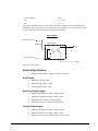
Step 2. Configuring Jumpers on the DMC-3425
Master Reset and Upgrade Jumper
JP1 contains two jumpers, MRST and UPGD. The MRST jumper is the Master Reset jumper. When
MRST is connected, the controller will perform a master reset upon PC power up or upon the reset
input going low. Whenever the controller has a master reset, all programs, arrays, variables, and
motion control parameters stored in EEPROM will be ERASED.
The UPGD jumper enables the user to unconditionally update the controller’s firmware. This jumper
is not necessary for firmware updates when the controller is operating normally, but may be necessary
in cases of corrupted EEPROM. EEPROM corruption should never occur, however, it is possible if

10 • Chapter 2 Getting Started DMC-3425
there is a power fault during a firmware update. If EEPROM corruption occurs, your controller may
not operate properly. In this case, install the UPGD Jumper and use the update firmware function on
the Galil Smart Terminal or WSDK to re-load the system firmware.
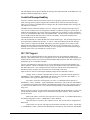
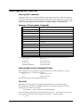
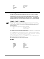
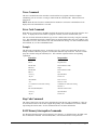
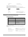
Setting the Baud Rate on the DMC-3425
The jumpers labeled “9600” and “1200” at JP1 allow the user to select the serial communication baud
rate. The baud rate can be set using the following table:
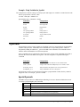
JUMPER SETTINGS BAUD RATE
9600 1200 --
OFF OFF 19200
ON OFF 9600
OFF ON 1200
The default baud rate for the controller is 19.2k.
Selecting MO as default on the DMC-3425
The default condition for the motor on the DMC-3425 is the servo on (SH) state. This will enable the
amplifiers upon power up of the controller. This state can be changed to the motor off (MO) default by
placing a jumper at JP2 across the MO terminals. This will power up the controller with the amplifiers
disabled and the motor command off. The SH command must then be given in order for the servos or
steppers to operate.
Stepper Motor Jumpers
The DMC-3415 is user configurable to control either a servo motor or a stepper motor. The DMC-
3425 is factory default to servo control, but may also control two steppers if ordered from the factory
as a DMC-3425-Stepper.
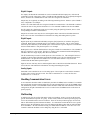
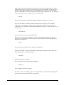
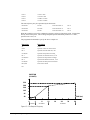
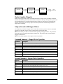
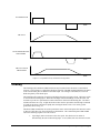
To configure the DMC-3415 for stepper output, two jumpers must be placed on the controller. First,
the SMX jumper at location JP2 must be installed. This configures the board for step/direction output.
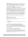
Second, the jumpers at location JP3 must be moved from the MC position to the SD position as shown
in Figure 2.2. This configures the output pins on the controller to output step and direction instead of
the analog motor command.
The configuration for two stepper motors on the DMC-3425-Stepper is handled at the factory. The
same procedure is used, placing jumpers on SMX and SMY at location JP2, and moving the SD/MC
jumpers at location JP3. A board modification is also required, which should only be handled by Galil
technicians.
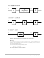
MCSD
JP3
MC SD
JP3
Setting for analog motor command Setting for step/direction output
Figure 2.2 - Jumper settings for motor command output

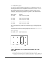
DMC-3425 Chapter 2 Getting Started• 11
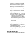
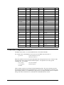
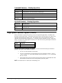
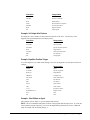
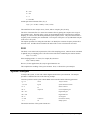
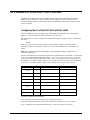
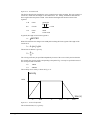
Axis Configuration Jumpers
When using the HC automatic configuration, jumpers must be set to indicate which controller is the
master and which controllers are slaves. Depending on the configuration of the jumpers, a controller
will be set up as either the A (B) master or any of the axes slaves.
The 8-pin jumper, found at location J4 next to the Molex power connector, is used to select axes
configurations. Jumpers at this location are labeled A1, A2, A4 and A8, which represent the binary
value for each of the 8 axes within a system. The following chart shows proper jumper selection for
each of the DMC-3415 or DMC-3425’s in a system.
Master A (B) axis No Jumpers
Slave Axis B A1 On A2 Off A4 Off A8 Off
Slave Axes C A1 Off A2 On A4 Off A8 Off
Slave Axis D A1 On A2 On A4 Off A8 Off
Slave Axes E A1 Off A2 Off A4 On A8 Off
Slave Axis F A1 On A2 Off A4 On A8 Off
Slave Axes G A1 Off A2 On A4 On A8 Off
Slave Axis H A1 On A2 On A4 On A8 Off
Jumpers on a card are used to denote the first axis it represents in a system. Therefore, a DMC-3415
takes up a single jumper setting. A DMC-3425 is selected with a single jumper setting but represents
two axes.
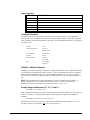
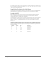
For example, the jumper settings for a system with a DMC-3415 master A axis, a DMC-3425 slave BC
axis and a DMC-3415 slave D axis, the following jumper settings would be used.
Master A – No Jumpers
Slave Axis BC – A1 On A2 Off A4 Off A8 Off
Slave Axis D – A1 On A2 On A4 Off A8 Off
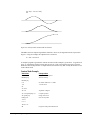
A8
A1 A2 A4
Fig. 2.3 – Example jumper settings for DMC-3425 E, F axis configuration.
Step 3. Connecting AC or DC power and the Serial Cable to the
DMC-3425
1. Insert 37-pin cable to J3. Connect the other end of the cable to the ICM-1460.
2. If using serial communications, use the 9-pin RS232 ribbon cable to connect the SERIAL port
of the DMC-3425 to your computer or terminal communications port. The DMC-3425 serial

12 • Chapter 2 Getting Started DMC-3425
port is configured as DATASET. Your computer or terminal must be configured as a
DATATERM for full duplex, no parity, 8 bits data, one start bit and one stop bit.
Your computer needs to be configured as a "dumb" terminal that sends ASCII characters as
they are typed to the DMC-3425.
Connections to the controller for Ethernet communication are covered in Step 5.
3. If using the card level version, apply ±12V and +5V power to the J5 connector. If using the
box level version, connect the AC cord to a power outlet. AC power requirements for the
controller are single phase, 50 or 60 Hz at 90 to 260 VAC.
4. Applying power will turn on the green LED power indicator.
Step 4. Installing the Communications Software
After applying power to the computer, you should install the Galil software that enables
communication between the controller and PC.
Using DOS:
Using the Galil Software CD-ROM, go to the directory, DMCDOS. Type "INSTALL" at the DOS
prompt and follow the directions.
Using Windows 3.x (16 bit versions):
Using the Galil Software CD ROM, go to the directory, DMCWIN16. Run DMCWIN16.exe at the
Command prompt and follow the directions.
Using Windows 95, NT or 98 (32 bit versions):
The Galil Software CD-ROM will automatically begin the installation procedure when the CD-ROM is
installed. After installing the Galil CD-ROM software on your computer, you can easily install other
software components as desired. To install the basic communications software, run the Galil Software
CD-ROM and choose “DMC Smart Terminal”. This will install the Galil Terminal that can be used
for communication.
Step 5. Establishing Communication between the DMC-3425 and the
host PC
Note: This section will show how to communicate with a single DMC-3425 or DMC-3415 controller.
If the controllers will be configured in a multi-axis, distributed control system, only the master axis
needs an IP address actively configured.
Communicating through the RS-232 Serial Communications Port
Connect the DMC-3425 serial port to your computer via the Galil CABLE-9PIN-D (RS-232 Cable).
Using Galil Software for DOS
To communicate with the DMC-3425, type TALK2DMC at the prompt. Once you have established
communication, the terminal display should show a colon, :. If you do not receive a colon, press the
carriage return. If a colon prompt is not returned, there is most likely an incorrect setting of the serial
communications port. The user must ensure that the correct communication port and baud rate are
specified when attempting to communicate with the controller. Please note that the serial port on the
controller must be set for handshake mode for proper communication with Galil software. The user
must also insure that the proper serial cable is being used. See appendix for pin-out of serial port.
Page is loading ...
Page is loading ...
Page is loading ...
Page is loading ...
Page is loading ...
Page is loading ...
Page is loading ...
Page is loading ...
Page is loading ...
Page is loading ...
Page is loading ...
Page is loading ...
Page is loading ...
Page is loading ...
Page is loading ...
Page is loading ...
Page is loading ...
Page is loading ...
Page is loading ...
Page is loading ...
Page is loading ...
Page is loading ...
Page is loading ...
Page is loading ...
Page is loading ...
Page is loading ...
Page is loading ...
Page is loading ...
Page is loading ...
Page is loading ...
Page is loading ...
Page is loading ...
Page is loading ...
Page is loading ...
Page is loading ...
Page is loading ...
Page is loading ...
Page is loading ...
Page is loading ...
Page is loading ...
Page is loading ...
Page is loading ...
Page is loading ...
Page is loading ...
Page is loading ...
Page is loading ...
Page is loading ...
Page is loading ...
Page is loading ...
Page is loading ...
Page is loading ...
Page is loading ...
Page is loading ...
Page is loading ...
Page is loading ...
Page is loading ...
Page is loading ...
Page is loading ...
Page is loading ...
Page is loading ...
Page is loading ...
Page is loading ...
Page is loading ...
Page is loading ...
Page is loading ...
Page is loading ...
Page is loading ...
Page is loading ...
Page is loading ...
Page is loading ...
Page is loading ...
Page is loading ...
Page is loading ...
Page is loading ...
Page is loading ...
Page is loading ...
Page is loading ...
Page is loading ...
Page is loading ...
Page is loading ...
Page is loading ...
Page is loading ...
Page is loading ...
Page is loading ...
Page is loading ...
Page is loading ...
Page is loading ...
Page is loading ...
Page is loading ...
Page is loading ...
Page is loading ...
Page is loading ...
Page is loading ...
Page is loading ...
Page is loading ...
Page is loading ...
Page is loading ...
Page is loading ...
Page is loading ...
Page is loading ...
Page is loading ...
Page is loading ...
Page is loading ...
Page is loading ...
Page is loading ...
Page is loading ...
Page is loading ...
Page is loading ...
Page is loading ...
Page is loading ...
Page is loading ...
Page is loading ...
Page is loading ...
Page is loading ...
Page is loading ...
Page is loading ...
Page is loading ...
Page is loading ...
Page is loading ...
Page is loading ...
Page is loading ...
Page is loading ...
Page is loading ...
Page is loading ...
Page is loading ...
Page is loading ...
Page is loading ...
Page is loading ...
Page is loading ...
Page is loading ...
Page is loading ...
Page is loading ...
Page is loading ...
Page is loading ...
Page is loading ...
Page is loading ...
Page is loading ...
Page is loading ...
Page is loading ...
Page is loading ...
Page is loading ...
Page is loading ...
Page is loading ...
Page is loading ...
Page is loading ...
Page is loading ...
Page is loading ...
Page is loading ...
Page is loading ...
Page is loading ...
Page is loading ...
Page is loading ...
Page is loading ...
Page is loading ...
Page is loading ...
Page is loading ...
Page is loading ...
Page is loading ...
Page is loading ...
Page is loading ...
Page is loading ...
Page is loading ...
Page is loading ...
Page is loading ...
Page is loading ...
Page is loading ...
Page is loading ...
Page is loading ...
Page is loading ...
Page is loading ...
Page is loading ...
Page is loading ...
Page is loading ...
Page is loading ...
Page is loading ...
Page is loading ...
Page is loading ...
Page is loading ...
Page is loading ...
Page is loading ...
Page is loading ...
Page is loading ...
Page is loading ...
Page is loading ...
Page is loading ...
Page is loading ...
Page is loading ...
Page is loading ...
Page is loading ...
Page is loading ...
-
 1
1
-
 2
2
-
 3
3
-
 4
4
-
 5
5
-
 6
6
-
 7
7
-
 8
8
-
 9
9
-
 10
10
-
 11
11
-
 12
12
-
 13
13
-
 14
14
-
 15
15
-
 16
16
-
 17
17
-
 18
18
-
 19
19
-
 20
20
-
 21
21
-
 22
22
-
 23
23
-
 24
24
-
 25
25
-
 26
26
-
 27
27
-
 28
28
-
 29
29
-
 30
30
-
 31
31
-
 32
32
-
 33
33
-
 34
34
-
 35
35
-
 36
36
-
 37
37
-
 38
38
-
 39
39
-
 40
40
-
 41
41
-
 42
42
-
 43
43
-
 44
44
-
 45
45
-
 46
46
-
 47
47
-
 48
48
-
 49
49
-
 50
50
-
 51
51
-
 52
52
-
 53
53
-
 54
54
-
 55
55
-
 56
56
-
 57
57
-
 58
58
-
 59
59
-
 60
60
-
 61
61
-
 62
62
-
 63
63
-
 64
64
-
 65
65
-
 66
66
-
 67
67
-
 68
68
-
 69
69
-
 70
70
-
 71
71
-
 72
72
-
 73
73
-
 74
74
-
 75
75
-
 76
76
-
 77
77
-
 78
78
-
 79
79
-
 80
80
-
 81
81
-
 82
82
-
 83
83
-
 84
84
-
 85
85
-
 86
86
-
 87
87
-
 88
88
-
 89
89
-
 90
90
-
 91
91
-
 92
92
-
 93
93
-
 94
94
-
 95
95
-
 96
96
-
 97
97
-
 98
98
-
 99
99
-
 100
100
-
 101
101
-
 102
102
-
 103
103
-
 104
104
-
 105
105
-
 106
106
-
 107
107
-
 108
108
-
 109
109
-
 110
110
-
 111
111
-
 112
112
-
 113
113
-
 114
114
-
 115
115
-
 116
116
-
 117
117
-
 118
118
-
 119
119
-
 120
120
-
 121
121
-
 122
122
-
 123
123
-
 124
124
-
 125
125
-
 126
126
-
 127
127
-
 128
128
-
 129
129
-
 130
130
-
 131
131
-
 132
132
-
 133
133
-
 134
134
-
 135
135
-
 136
136
-
 137
137
-
 138
138
-
 139
139
-
 140
140
-
 141
141
-
 142
142
-
 143
143
-
 144
144
-
 145
145
-
 146
146
-
 147
147
-
 148
148
-
 149
149
-
 150
150
-
 151
151
-
 152
152
-
 153
153
-
 154
154
-
 155
155
-
 156
156
-
 157
157
-
 158
158
-
 159
159
-
 160
160
-
 161
161
-
 162
162
-
 163
163
-
 164
164
-
 165
165
-
 166
166
-
 167
167
-
 168
168
-
 169
169
-
 170
170
-
 171
171
-
 172
172
-
 173
173
-
 174
174
-
 175
175
-
 176
176
-
 177
177
-
 178
178
-
 179
179
-
 180
180
-
 181
181
-
 182
182
-
 183
183
-
 184
184
-
 185
185
-
 186
186
-
 187
187
-
 188
188
-
 189
189
-
 190
190
-
 191
191
-
 192
192
-
 193
193
-
 194
194
-
 195
195
-
 196
196
-
 197
197
-
 198
198
-
 199
199
-
 200
200
-
 201
201
-
 202
202
-
 203
203
-
 204
204
-
 205
205
-
 206
206
-
 207
207
-
 208
208
-
 209
209
-
 210
210


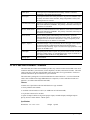
Galil Home Security System DMC-3425 User manual
- Type
- User manual
- This manual is also suitable for
Ask a question and I''ll find the answer in the document
Finding information in a document is now easier with AI
Related papers


Other documents
-
Mitsubishi Electric Simple Motion Board User manual
-
Altinex CP7317RS User manual
-
National Instruments MCA-7724 User manual
-
 Varedan Technologies VSA-1530-2 Product User Manual
-
 Beckhoff AX2000 Setup Manual
-
 Newport CONEX-PP User manual
-
Omega STM, ST, Stac6, 1240i, 3540i, si3540 Series Owner's manual
-
 RMS R325I User manual
-
SMC Networks 4000 User manual
-
Linear 45 VDC User manual


