Page is loading ...

FPC 5000
Matrix 12800 Switcher Front Panel Controller
68-556-05 Rev. A
Printed in the USA
05 03

This symbol is intended to alert the user of important operating and maintenance
(servicing) instructions in the literature provided with the equipment.
This symbol is intended to alert the user of the presence of uninsulated dangerous
voltage within the product's enclosure that may present a risk of electric shock.
Caution
Read Instructions • Read and understand all safety and operating instructions before using the
equipment.
Retain Instructions • The safety instructions should be kept for future reference.
Follow Warnings • Follow all warnings and instructions marked on the equipment or in the user
information.
Avoid Attachments • Do not use tools or attachments that are not recommended by the equipment
manufacturer because they may be hazardous.
Warning
Power sources • This equipment should be operated only from the power source indicated on the
product. This equipment is intended to be used with a main power system with a grounded
(neutral) conductor. The third (grounding) pin is a safety feature, do not attempt to bypass or
disable it.
Power disconnection • To remove power from the equipment safely, remove all power cords from
the rear of the equipment, or the desktop power module (if detachable), or from the power
source receptacle (wall plug).
Power cord protection • Power cords should be routed so that they are not likely to be stepped on or
pinched by items placed upon or against them.
Servicing • Refer all servicing to qualified service personnel. There are no user-serviceable parts
inside. To prevent the risk of shock, do not attempt to service this equipment yourself because
opening or removing covers may expose you to dangerous voltage or other hazards.
Slots and openings • If the equipment has slots or holes in the enclosure, these are provided to
prevent overheating of sensitive components inside. These openings must never be blocked by
other objects.
Lithium battery • There is a danger of explosion if battery is incorrectly replaced. Replace it only
with the same or equivalent type recommended by the manufacturer. Dispose of used batteries
according to the manufacturer's instructions.
Ce symbole sert à avertir l’utilisateur que la documentation fournie avec le matériel
contient des instructions importantes concernant l’exploitation et la maintenance
(réparation).
Ce symbole sert à avertir l’utilisateur de la présence dans le boîtier de l’appareil de
tensions dangereuses non isolées posant des risques d’électrocution.
Attention
Lire les instructions• Prendre connaissance de toutes les consignes de sécurité et d’exploitation avant
d’utiliser le matériel.
Conserver les instructions• Ranger les consignes de sécurité afin de pouvoir les consulter à l’avenir.
Respecter les avertissements • Observer tous les avertissements et consignes marqués sur le matériel ou
présentés dans la documentation utilisateur.
Eviter les pièces de fixation • Ne pas utiliser de pièces de fixation ni d’outils non recommandés par le
fabricant du matériel car cela risquerait de poser certains dangers.
Avertissement
Alimentations• Ne faire fonctionner ce matériel qu’avec la source d’alimentation indiquée sur
l’appareil. Ce matériel doit être utilisé avec une alimentation principale comportant un fil de
terre (neutre). Le troisième contact (de mise à la terre) constitue un dispositif de sécurité :
n’essayez pas de la contourner ni de la désactiver.
Déconnexion de l’alimentation• Pour mettre le matériel hors tension sans danger, déconnectez tous
les cordons d’alimentation de l’arrière de l’appareil ou du module d’alimentation de bureau (s’il
est amovible) ou encore de la prise secteur.
Protection du cordon d’alimentation • Acheminer les cordons d’alimentation de manière à ce que
personne ne risque de marcher dessus et à ce qu’ils ne soient pas écrasés ou pincés par des
objets.
Réparation-maintenance • Faire exécuter toutes les interventions de réparation-maintenance par un
technicien qualifié. Aucun des éléments internes ne peut être réparé par l’utilisateur. Afin
d’éviter tout danger d’électrocution, l’utilisateur ne doit pas essayer de procéder lui-même à ces
opérations car l’ouverture ou le retrait des couvercles risquent de l’exposer à de hautes tensions
et autres dangers.
Fentes et orifices • Si le boîtier de l’appareil comporte des fentes ou des orifices, ceux-ci servent à
empêcher les composants internes sensibles de surchauffer. Ces ouvertures ne doivent jamais
être bloquées par des objets.
Lithium Batterie • Il a danger d'explosion s'll y a remplacment incorrect de la batterie. Remplacer
uniquement avec une batterie du meme type ou d'un ype equivalent recommande par le
constructeur. Mettre au reut les batteries usagees conformement aux instructions du fabricant.
Safety Instructions • English
Consignes de Sécurité • Français
Sicherheitsanleitungen • Deutsch
Dieses Symbol soll dem Benutzer in der im Lieferumfang enthaltenen
Dokumentation besonders wichtige Hinweise zur Bedienung und Wartung
(Instandhaltung) geben.
Dieses Symbol soll den Benutzer darauf aufmerksam machen, daß im Inneren des
Gehäuses dieses Produktes gefährliche Spannungen, die nicht isoliert sind und
die einen elektrischen Schock verursachen können, herrschen.
Achtung
Lesen der Anleitungen • Bevor Sie das Gerät zum ersten Mal verwenden, sollten Sie alle Sicherheits-und
Bedienungsanleitungen genau durchlesen und verstehen.
Aufbewahren der Anleitungen • Die Hinweise zur elektrischen Sicherheit des Produktes sollten Sie
aufbewahren, damit Sie im Bedarfsfall darauf zurückgreifen können.
Befolgen der Warnhinweise • Befolgen Sie alle Warnhinweise und Anleitungen auf dem Gerät oder in
der Benutzerdokumentation.
Keine Zusatzgeräte • Verwenden Sie keine Werkzeuge oder Zusatzgeräte, die nicht ausdrücklich vom
Hersteller empfohlen wurden, da diese eine Gefahrenquelle darstellen können.
Vorsicht
Stromquellen • Dieses Gerät sollte nur über die auf dem Produkt angegebene Stromquelle betrieben
werden. Dieses Gerät wurde für eine Verwendung mit einer Hauptstromleitung mit einem
geerdeten (neutralen) Leiter konzipiert. Der dritte Kontakt ist für einen Erdanschluß, und stellt
eine Sicherheitsfunktion dar. Diese sollte nicht umgangen oder außer Betrieb gesetzt werden.
Stromunterbrechung • Um das Gerät auf sichere Weise vom Netz zu trennen, sollten Sie alle
Netzkabel aus der Rückseite des Gerätes, aus der externen Stomversorgung (falls dies möglich
ist) oder aus der Wandsteckdose ziehen.
Schutz des Netzkabels • Netzkabel sollten stets so verlegt werden, daß sie nicht im Weg liegen und
niemand darauf treten kann oder Objekte darauf- oder unmittelbar dagegengestellt werden
können.
Wartung • Alle Wartungsmaßnahmen sollten nur von qualifiziertem Servicepersonal durchgeführt
werden. Die internen Komponenten des Gerätes sind wartungsfrei. Zur Vermeidung eines
elektrischen Schocks versuchen Sie in keinem Fall, dieses Gerät selbst öffnen, da beim Entfernen
der Abdeckungen die Gefahr eines elektrischen Schlags und/oder andere Gefahren bestehen.
Schlitze und Öffnungen • Wenn das Gerät Schlitze oder Löcher im Gehäuse aufweist, dienen diese
zur Vermeidung einer Überhitzung der empfindlichen Teile im Inneren. Diese Öffnungen dürfen
niemals von anderen Objekten blockiert werden.
Litium-Batterie • Explosionsgefahr, falls die Batterie nicht richtig ersetzt wird. Ersetzen Sie
verbrauchte Batterien nur durch den gleichen oder einen vergleichbaren Batterietyp, der auch
vom Hersteller empfohlen wird. Entsorgen Sie verbrauchte Batterien bitte gemäß den
Herstelleranweisungen.
Este símbolo se utiliza para advertir al usuario sobre instrucciones importantes de
operación y mantenimiento (o cambio de partes) que se desean destacar en el
contenido de la documentación suministrada con los equipos.
Este símbolo se utiliza para advertir al usuario sobre la presencia de elementos con
voltaje peligroso sin protección aislante, que puedan encontrarse dentro de la caja
o alojamiento del producto, y que puedan representar riesgo de electrocución.
Precaucion
Leer las instrucciones • Leer y analizar todas las instrucciones de operación y seguridad, antes de usar
el equipo.
Conservar las instrucciones • Conservar las instrucciones de seguridad para futura consulta.
Obedecer las advertencias • Todas las advertencias e instrucciones marcadas en el equipo o en la
documentación del usuario, deben ser obedecidas.
Evitar el uso de accesorios • No usar herramientas o accesorios que no sean especificamente
recomendados por el fabricante, ya que podrian implicar riesgos.
Advertencia
Alimentación eléctrica • Este equipo debe conectarse únicamente a la fuente/tipo de alimentación
eléctrica indicada en el mismo. La alimentación eléctrica de este equipo debe provenir de un
sistema de distribución general con conductor neutro a tierra. La tercera pata (puesta a tierra) es
una medida de seguridad, no puentearia ni eliminaria.
Desconexión de alimentación eléctrica • Para desconectar con seguridad la acometida de
alimentación eléctrica al equipo, desenchufar todos los cables de alimentación en el panel trasero
del equipo, o desenchufar el módulo de alimentación (si fuera independiente), o desenchufar el
cable del receptáculo de la pared.
Protección del cables de alimentación • Los cables de alimentación eléctrica se deben instalar en
lugares donde no sean pisados ni apretados por objetos que se puedan apoyar sobre ellos.
Reparaciones/mantenimiento • Solicitar siempre los servicios técnicos de personal calificado. En el
interior no hay partes a las que el usuario deba acceder. Para evitar riesgo de electrocución, no
intentar personalmente la reparación/mantenimiento de este equipo, ya que al abrir o extraer las
tapas puede quedar expuesto a voltajes peligrosos u otros riesgos.
Ranuras y aberturas • Si el equipo posee ranuras o orificios en su caja/alojamiento, es para evitar el
sobrecalientamiento de componentes internos sensibles. Estas aberturas nunca se deben obstruir
con otros objetos.
Batería de litio • Existe riesgo de explosión si esta batería se coloca en la posición incorrecta. Cambiar
esta batería únicamente con el mismo tipo (o su equivalente) recomendado por el fabricante.
Desachar las baterías usadas siguiendo las instrucciones del fabricante.
Instrucciones de seguridad • Español
Precautions

i
FPC 5000 Front Panel Controller • Table of Contents
Table of Contents
Chapter 1 • Introduction ....................................................................................................... 1-1
About the Front Panel Controller ............................................................................... 1-2
About the Matrix 12800 System ................................................................................. 1-3
Definitions of Matrix Switcher Terms ...................................................................... 1-4
Chapter 2 • FPC Installation and Operation ............................................................. 2-1
Installation Overview ....................................................................................................... 2-2
Unpacking and Assembling the Front Panel Controller .................................. 2-2
Rack Mounting the FPC Assembly .............................................................................. 2-5
Rear Panel Connections ................................................................................................... 2-5
Cabling and RJ-45 connector wiring ................................................................................. 2-8
Front Panel Features and Operation ......................................................................... 2-9
Upgrading the Software ............................................................................................... 2-10
Chapter 3 • Matrix 12800 Operation ............................................................................. 3-1
Introduction........................................................................................................................... 3-2
Operating the Touch Panel ............................................................................................. 3-2
Using the keyboards .......................................................................................................... 3-2
Using the keypads .............................................................................................................. 3-3
Using the on-screen scroll boxes ....................................................................................... 3-3
Starting Up the Controller and Logging In and Out ......................................... 3-4
Demo Mode ........................................................................................................................... 3-7
Navigating the Screens .................................................................................................... 3-7
User Screens......................................................................................................................... 3-10
I/O screens ........................................................................................................................ 3-10
Viewing ties ................................................................................................................ 3-10
Viewing inputs tied to a specified output ........................................................... 3-12
Viewing outputs tied to a specific input .................................................................. 3-13
Viewing all ties ........................................................................................................... 3-13
Creating ties ............................................................................................................... 3-14
Creating ties using the Make Ties: dual keypad screen ........................................ 3-15
Creating ties using the Make Ties: alternate view screen ....................................... 3-16
Preset screens ................................................................................................................... 3-17
Save, recall, or delete a global preset ......................................................................... 3-17
Save, recall, or delete a room preset .......................................................................... 3-19
Name a global or room preset .................................................................................... 3-19
Mute screen ...................................................................................................................... 3-20
DSVP screen ...................................................................................................................... 3-21

ii FPC 5000 Front Panel Controller • Table of Contents
Table of Contents, cont’d
Admin Screens.................................................................................................................... 3-22
Status screens ................................................................................................................... 3-22
Status screen, System area .......................................................................................... 3-22
Status screen, BME area .............................................................................................. 3-23
Remotes screen ................................................................................................................ 3-23
TCP/IP screen .................................................................................................................... 3-24
Password fields ........................................................................................................... 3-25
Date field .................................................................................................................... 3-25
Time (GMT) field ......................................................................................................... 3-25
Matrix Name field....................................................................................................... 3-25
Hardware Address field .............................................................................................. 3-25
Matrix IP Address field ................................................................................................ 3-25
Gateway IP Address field ............................................................................................ 3-25
Subnet mask field ....................................................................................................... 3-26
FPC IP Address field .................................................................................................... 3-26
E-Mail screen .................................................................................................................... 3-26
Mail Server IP Address field ........................................................................................ 3-27
Mail Server E-Mail User Name field ............................................................................ 3-27
Mail Server Password field .......................................................................................... 3-27
E-mail Addressee fields ............................................................................................... 3-27
Miscellaneous screen ....................................................................................................... 3-28
File Manager screen ................................................................................................... 3-29
Function Keys screen .................................................................................................. 3-30
I/O Physical Connectors screen .................................................................................... 3-32
Naming inputs and outputs ................................................................................. 3-33
Calibrate TouchScreen button .................................................................................... 3-33
Re-Install FPC Software button ................................................................................... 3-33
Setup Screens...................................................................................................................... 3-33
Delay screen ..................................................................................................................... 3-34
Audio screen .................................................................................................................... 3-35
Reset screen ...................................................................................................................... 3-36
Blank button .................................................................................................................... 3-36
Subnetting — A Primer .................................................................................................. 3-37
68-556-05 Rev. A
Printed in the USA
05 03
All trademarks mentioned in this manual are the properties of their respective owners.

FPC 5000 Front Panel Controller
1
Chapter One
Introduction
About the Front Panel Controller
About the Matrix 12800 System
Definitions of Matrix Switcher Terms

Introduction, cont’d
FPC 5000 Front Panel Controller • Introduction1-2
Introduction
About the Front Panel Controller
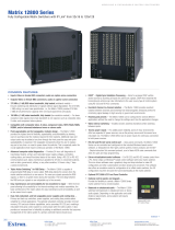
The Extron FPC 5000 Front Panel Controller (figure 1-1) is an optional element of
the Matrix 12800 family of matrix switchers. The FPC 5000 is a rack-mountable
device that provides front panel control of the matrix, including configuration of
the inputs and outputs and control of additional system features.
MATRIX SWICHER CONTROLLER
RESET
PWR
HDD
T/R
FPC 5000
Figure 1-1 — Front panel controller
The FPC 5000 has a large LCD touch-panel display that allows direct access and
total control over all presets and switching functions. FPC 5000 screens provide an
intuitive interface for quick and easy setup and programming.
The FPC 5000 assembly consists of the FPC computer and a rack-mountable, 7U
high, 19” wide metal panel.

1-3FPC 5000 Front Panel Controller • Introduction
About the Matrix 12800 System
The Matrix 12800 system (figure 1-2) is made up of a series of matrix switcher basic
module enclosures (BMEs). The family of BMEs allows you to create a video and/
or audio matrix system with up to 128 inputs and 128 outputs specifically tailored
to meet your requirements.
EXT. FDD
MOUSEK/B
NET
PRN
AC 100V-230V
INPUT
DIO
COM4
COM3
VGA
COM2
COM1
I
o
DISCONNECT BOTH POWER CORDS BEFORE SERVICING.
100-240V 5.0A MAX 50/60Hz FUSE 250V 5.0A T
100-240V 5.0A MAX 50/60Hz FUSE 250V 5.0A T
PRIMARY AC
POWER INPUT
POWER SUPPLIES
CPU STATUS
LISTED
1T23
I.T.E.
BME
PRIMARY
REDUNDANT
CAUTION
For protection against risk of
fire, replace only with same
type and rating of fuse.
PRIMARY
REDUNDANT
REDUNDANT AC
POWER INPUT
ANAHEIM, CA
SYNC
MADE IN USA
+V -V
ADDRESS
4
-
+
INPUTS
OUTPUTS
SECONDARY
MCP/MKP COMM ETHERNET BME COMM
IN OUT
A B C D E
PRIMARY FPC COMM
Tx
Rx
Tx
Rx
Tx
Rx
Tx
Rx
Tx
Rx
Tx
Rx
RS 232/422 RS 232/422
1
2
3
4
5
6
7
8
9
10
11
12
13
14
15
16
1
2
3
4
5
6
7
8
9
10
11
12
13
14
15
16
17
18
19
20
21
22
23
24
25
26
27
28
29
30
31
32
33
34
35
36
37
38
39
40
41
42
43
44
45
46
47
48
17
18
19
20
21
22
23
24
25
26
27
28
29
30
31
32
33
34
35
36
37
38
39
40
41
42
43
44
45
46
47
48
49
50
51
52
53
54
55
56
57
58
59
60
61
62
63
64
IN
OUT
49
50
51
52
53
54
55
56
57
58
59
60
61
62
63
64
OUTPUTS
65
66
67
68
69
70
71
72
73
74
75
76
77
78
79
80
65
66
67
68
69
70
71
72
73
74
75
76
77
78
79
80
81
82
83
84
85
86
87
88
89
90
91
92
93
94
95
96
97
98
99
100
101
102
103
104
105
106
107
108
109
110
111
112
81
82
83
84
85
86
87
88
89
90
91
92
93
94
95
96
97
98
99
100
101
102
103
104
105
106
107
108
109
110
111
112
113
114
115
116
117
118
119
120
121
122
123
124
125
126
127
128
113
114
115
116
117
118
119
120
121
122
123
124
125
126
127
128
DISCONNECT BOTH POWER CORDS BEFORE SERVICING.
100-240V 5.0A MAX 50/60Hz FUSE 250V 5.0A T
100-240V 5.0A MAX 50/60Hz FUSE 250V 5.0A T
PRIMARY AC
POWER INPUT
POWER SUPPLIES
CPU STATUS
LISTED
1T23
I.T.E.
BME
PRIMARY
REDUNDANT
CAUTION
For protection against risk of
fire, replace only with same
type and rating of fuse.
PRIMARY
REDUNDANT
REDUNDANT AC
POWER INPUT
ANAHEIM, CA
MADE IN USA
+V -V
ADDRESS
4
-
+
SECONDARY
MCP/MKP COMM ETHERNET BME COMM
IN OUT
A B C D E
PRIMARY FPC COMM
Tx
Rx
Tx
Rx
Tx
Rx
Tx
Rx
Tx
Rx
Tx
Rx
RS 232/422 RS 232/422
INPUTS
OUTPUTS
1-8 9-16 17-24
25-32 33-40 41-48 49-56
57-64
65-72 73-80
81-88 89-96 97-104 105-112
113-120
121-128
Matrix 12800 Wideband Video
Computer
Projector
Matrix 12800 Sync
Matrix 12800 Audio
R
G
B
H
V
R
G
B
BME COMM
Interconnecting
Cable
H
V
Audio
Audio
FPC 5000
Figure 1-2 — Typical Matrix 12800 system application

Introduction, cont’d
FPC 5000 Front Panel Controller • Introduction1-4
The Matrix 12800 Series includes:
• Wideband video switcher BME — A rack-mountable 10U switcher that
routes video (red (R), green (G), and blue (B) video planes, component video,
S-video, and composite video) from any input to any one or more outputs.
• Sync switcher BME — A rack-mountable 10U switcher that routes horizontal
(H) and vertical (V) or composite sync from any input to any one or more
outputs.
• Audio switcher BME — A rack-mountable 10U switcher that routes balanced
or unbalanced stereo or mono audio from any input to any one or more
outputs.
• FPC 5000 Front Panel Controller — A rack-mountable 7U device that permits
front panel configuration of the inputs and outputs and control of additional
system features.
The front panel controller interfaces with the master BME (BME 0) of a Matrix
12800 system via the BME’s Ethernet port, either directly or as part of an Ethernet
local area network (LAN).
Definitions of Matrix Switcher Terms
The following terms apply to Extron matrix switchers, and are used throughout
this manual:
Tie — An input-to-output connection.
Set of ties — An input tied to two or more outputs. (An output can never be
tied to more than one input.)
Configuration — One tie or one or more sets of ties.
Current configuration — The configuration that is currently being used (also
called configuration 0).
Global memory preset — A configuration that has been stored. The
Matrix 12800 can support up to 64 global presets. When a global preset is
retrieved from memory, it becomes the current configuration.
Room — A room consists of a smaller subset of virtual outputs that are
logically related to each other, as determined by the operator. The
Matrix 12800 supports up to 32 rooms, each of which consists of from 1 to 16
virtual outputs. Each room can have up to 10 presets.
Room memory preset — A configuration consisting of virtual outputs in a
single room that has been stored. When a room preset is retrieved from
memory, it becomes the current configuration.
BME 0 — The BME that has been configured as master in a multiple-BME
Matrix 12800 system.

FPC 5000 Front Panel Controller
2
Chapter Two
FPC Installation and Operation
Installation Overview
Unpacking and Assembling the Front Panel Controller
Rack Mounting the FPC Assembly
Rear Panel Connections
Front Panel Features and Operation
Upgrading the Software

FPC Installation and Operation, cont’d
FPC 5000 Front Panel Controller • FPC Installation and Operation2-2
FPC Installation and Operation
Installation Overview
The FPC 5000 assembly consists of the FPC computer and a rack-mountable, 7U
high, 19” wide metal panel.
As part of a complete Matrix 12800 system, the FPC 5000 can be installed in a rack
or a cabinet with the rest of the system BMEs. The controller is connected to the
Ethernet port of a switching BME. In a system with more than one switching BME,
the FPC must be connected to the BME that is designated as BME 0 in the system
(refer to the Matrix 12800 Wideband, Sync, or Audio Switchers User’s Manual, part
#68-556-01). If the BMEs are rack- or cabinet-mounted, they can be mounted in any
order.
Plan carefully before installing the equipment in a room. Poor planning can cause
problems. The number of cables involved can result in a cluttered appearance.
Power and ventilation requirements must be adequate. Although not noisy, the
background noise generated by a rack of Matrix 12800 switcher BMEs could be
distracting.
To install and set up the FPC 5000 for operation with a Matrix 12800 system,
perform the following steps:
1
Disconnect power from all of the BMEs.
2
Secure the FPC computer to the FPC mounting panel. See Unpacking and
Assembling the Front Panel Controller in this chapter.
3
Rack mount the front panel controller. See Rack Mounting the FPC Assembly in
this chapter.
4
Connect an Ethernet cable from the FPC to BME 0 of the Matrix 12800 system
or to the Ethernet LAN on which the Matrix 12800 system resides.
5
Connect the AC power cable to the FPC.
6
If not already accomplished, complete the installation and virtualization of
the rest of the Matrix 12800 system (refer to the Matrix 12800 Wideband, Sync,
or Audio Switchers User’s Manual, part #68-556-01).
7
Turn on the FPC 5000 and observe the FPC computer’s startup display.
Unpacking and Assembling the Front Panel Controller
The FPC 5000 is shipped unassembled to prevent damage to the mounting
hardware in shipment. Before the FPC assembly can be rack mounted, the FPC
computer must be mounted to the panel. The mounting hardware is included with
the controller. Assemble the controller as follows:
1. Open the FPC 5000 shipping carton and remove all of the protective foam
from the top and sides of the computer and rack-mountable panel.
CAUTION
Hold the computer and the panel together at the top and bottom when
removing the computer and panel from the shipping carton (figure 2-1).
The computer is loosely nested in the panel and could drop if it is not
properly supported.

2-3FPC 5000 Front Panel Controller • FPC Installation and Operation
2. Remove the computer and the panel from the shipping carton. Support the
FPC computer as shown in figure 2-1.
Figure 2-1 — A properly supported FPC computer and panel
3. Place the computer and panel on the tabletop with a book or other 1”-high
object under the computer to support it as it nests in the panel.
4. With the tabs up, angle one of the included mounting blocks and insert the
block’s two tabs into the slots on one corner of the FPC computer
(figure 2-2). Slide the mounting block up and then lower the
block so that the tabs in the block engage the sides of the
computer and the block’s side is flush against the computer’s
case.
Figure 2-2 — Computer and panel mounting block installation
Tabs
Mounting
Block

FPC Installation and Operation, cont’d
FPC 5000 Front Panel Controller • FPC Installation and Operation2-4
5. Repeat step 4 for each of the remaining three mounting blocks.
6. Thread one of the included 60 mm panhead machine screws into the top of
each mounting block. Repeat for the other screws.
7. Tighten the screws until they just contact the rack-mounting panel. Move the
panel as necessary to ensure that the four screws contact the panel in the inset
holes (figure 2-3).
CAUTION
Do not overtighten the screws. The screws may bend if overtightened. If
you are using a torque screwdriver, set the screwdriver to release at a
minimal amount of torque.
Figure 2-3 — Inserting the machine screws
8. Lift the FPC computer and tighten each screw until the panel is firmly flush
against the back side of the FPC computer’s LCD panel (figure 2-4).
Figure 2-4 — Fully assembled Front Panel Controller

2-5FPC 5000 Front Panel Controller • FPC Installation and Operation
Rack Mounting the FPC Assembly
The appropriate rack mounting hardware is included with the controller. Rack
mount the controller as follows:
1. Insert the controller assembly into the rack, align the holes in the mounting
panel with those of the rack.
2. Secure the controller assembly to the rack using the supplied machine screws.
Rear Panel Connections
All connectors are on the rear of the FPC 5000 (figure 2-5).
EXT. FDD
MOUSEK/B
NET
PRN
AC 100V-230V
INPUT
DIO
COM4
COM3
VGA
COM2
COM1
I
o
1
2 3
Figure 2-5 — FPC 5000 Front Panel Controller rear panel features
1
Net port — Connect one end of a Category (CAT) 5e or higher cable,
terminated with RJ-45 connectors, to the FPC 5000 via this RJ-45 connector.
The FPC 5000 ships with a 10-foot crossover CAT 5e cable.

FPC Installation and Operation, cont’d
FPC 5000 Front Panel Controller • FPC Installation and Operation2-6
For direct connection to BME 0 — Plug the RJ-45 connector on the opposite
end of the CAT 5e or higher cable directly into the BME 0 Ethernet port
(figure 2-6). Wire the CAT 5e or higher cable as a
crossover cable (See Cabling
and RJ-45 connector wiring in this chapter). For a multi-BME system, ensure
that you connect the FPC to BME 0.
MATRIX SWICHER CONTROLLER
PWR
HDD
T/R
RESET
FPC 5000
FPC 5000
Matrix 12800
Crossover Cable
MATRIX 12800
WIDEBAND VIDEO
Figure 2-6 — Connecting the FPC directly to a switcher BME
For Ethernet connection to the Matrix 12800 system — Plug the RJ-45
connector on the opposite end of the CAT 5e or higher cable into the Ethernet
LAN on which BME 0 of the Matrix 12800 system resides (figure 2-7). Wire
the CAT 5e or higher cable as a
patch (straight) cable (See Cabling and RJ-45
connector wiring in this chapter).
MATRIX SWICHER CONTROLLER
PWR
HDD
T/R
RESET
FPC 5000
Ethernet
FPC 5000
Matrix 12800
Laptop
Patch Cable
Patch Cable
MATRIX 12800
WIDEBAND VIDEO
Figure 2-7 — Connecting the FPC through a LAN
2
AC power input connector — Connect a standard IEC power cord between
the rear panel AC power input connector and a 100 to 240VAC, 50 Hz or
60 Hz power source.

2-7FPC 5000 Front Panel Controller • FPC Installation and Operation
3
Power ( / )switch — Toggle the power switch to the on ( ) position. After
approximately 2 minutes, observe that the LCD touch panel displays the FPC
start-up screen (figure 2-8). See chapter 3, Matrix 12800 Operation, for using
the FPC to operate the Matrix 12800 system.
Figure 2-8 — FPC 5000 Start-up screen

FPC Installation and Operation, cont’d
FPC 5000 Front Panel Controller • FPC Installation and Operation2-8
Cabling and RJ-45 connector wiring
It is vital that your cable between the FPC 5000 and the Matrix 12800 BME 0 or
LAN be the correct cable, and that it be properly terminated with the correct
pinout. This FPC link requires CAT 5e or CAT 6, unshielded twisted pair (UTP) or
shielded twisted pair (STP) cables, terminated with RJ-45 connectors. The cable
length is limited to 328’ (100 m).
Do not use standard telephone cables. Telephone cables will not support the
FPC-Matrix 12800 link.
Do not stretch or bend cables. Transmission errors can occur.
The cable must be properly terminated for your application (figure 2-9):
• Crossover cable — Direct connection between the FPC and BME 0.
• Patch (straight) cable — Connection of the FPC to an Ethernet LAN that also
hosts BME 0.
Clip DownSide
1
1&2
3&6 4&5
7&8
2345678
1Pins 2345678
RJ-45
connector
Patch (straight) cable
Twisted
Pairs
Side 1 Side 2
Pin Wire color Pin Wire color
1 White-orange 1 White-orange
2 Orange 2 Orange
3 White-green 3 White-green
4 Blue 4 Blue
5 White-blue 5 White-blue
6 Green 6 Green
7 White-brown 7 White-brown
8 Brown 8 Brown
Crossover cable
Side 1 Side 2
Pin Wire color Pin Wire color
1 White-orange 1 White-green
2 Orange 2 Green
3 White-green 3 White-orange
4 Blue 4 Blue
5 White-blue 5 White-blue
6 Green 6 Orange
7 White-brown 7 White-brown
8 Brown 8 Brown
Figure 2-9 — RJ-45 connector pinout tables

2-9FPC 5000 Front Panel Controller • FPC Installation and Operation
Front Panel Features and Operation
Other than the power switch, the remaining control and all of the FPC 5000
indicators are on the front panel (figure 2-10).
MATRIX SWICHER CONTROLLER
PWR
HDD
T/R
RESET
FPC 5000
2
4
3
5
1
Figure 2-10 — Front panel control and indicators
1
LCD touch panel — The LCD panel displays front panel controller screens.
The touch panel responds to selections that the operator makes by touching
the screen.
2
Power indicator — Lights to indicate power is connected and the FPC is
turned on.
3
H(ard) D(isk) D(rive) indicator — Lights to indicate that the FPC is accessing
its hard disk.
4
T(ransmit)/R(eceive) indicator — Lights to indicate that the FPC is
transmitting or receiving data on the Net port.
5
Reset button — Use a small screwdriver or tweeker to press the Reset button
if the FPC computer hangs up. This button reboots the computer.

FPC Installation and Operation, cont’d
FPC 5000 Front Panel Controller • FPC Installation and Operation2-10
Upgrading the Software
The Front Panel Controller software is factory installed on the FPC computer’s hard
drive and it is also included on a CD-ROM. Extron sends any needed software
upgrades on a CD-ROM.
Upgrade the FPC software as follows:
1. If necessary, log the FPC 5000 on to the Matrix 12800 system as an
administrator. See Starting Up the Controller and Logging In and Out in
chapter 3, Matrix 12800 Operation.
2. On the front panel LCD, touch the blue Admin button.
3. On the front panel LCD, touch the purple Misc button.
4. On the front panel LCD, touch the gray Re-Install FPC Software button. The
FPC prompts you to insert the CD-ROM containing the FPC software into the
CD tray. To exit without installing the software, touch on the gray Cancel
button.
5. On the rear of the FPC, press the eject button on the CD-ROM drive
(figure 2-11). The drive’s LED flashes and the CD tray partially ejects.
On the rear of the FPC, gently pull the CD tray to its fully extended position.
PRN
DIO
C
EXT. FDD
MOUSEK/B
NET
CD Eject
Button
Figure 2-11 — Eject button location

2-11FPC 5000 Front Panel Controller • FPC Installation and Operation
6. On the rear of the FPC, support the CD tray from behind with one hand while
you snap the program CD onto the tray spindle with the unlabeled (program)
side of the CD facing into the tray (figure 2-12).
PRN
AC 100V-230V
INPUT
DIO
COM4
COM3
COM2
C
O
EXT. FDD
MOUSEK/B
NET
Figure 2-12 — Inserting the program CD into the CD tray
7. On the rear of the FPC, gently push the CD tray back into the FPC computer
until it locks in place.
8. On the front panel, touch on the gray OK button.
9. Follow the on-screen instructions.
10. When the installation is complete, on the rear panel, press the eject button on
the CD-ROM drive. The drive’s LED flashes and the CD tray partially ejects.
11. Gently pull the CD tray to its fully extended position.
12. Support the CD tray from behind with one hand while you snap the program
CD off of the tray spindle.
13. Gently push the CD tray back into the FPC computer until it locks in place.

FPC Installation and Operation, cont’d
FPC 5000 Front Panel Controller • FPC Installation and Operation2-12
/