Visualint VI-JBR User guide

Category
Security camera accessories
Type
User guide

This manual is also suitable for

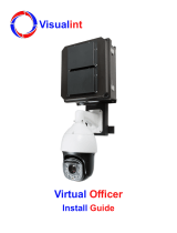
Visualint VI-JBR is a versatile junction box designed to accommodate a range of Visualint camera models, including the 1350, 1450, 1550, 3140, 7150, 7230, and 7650 with an attached arm mount. It can also be used with other Visualint cameras when supplemented with the Visualint pendant mount.

The VI-JBR features multiple cable entry points, allowing for flexible cable management. Its durable construction and included rubber cable glands ensure a waterproof seal, protecting your cables from the elements.

Install Guide for Visualint Junction Boxes
1. About This Guide
is guide is for both the VI-JB and the VI-JBR junction boxes. Where the two mounts have similar
procedures, the text is centered. Where they diverge, the text splits into le and right columns.
VI-JB
VI-JBR
2. Compatibility
is junction box can be used with a variety of Visualint
camera models: 1350, 1450, 1550, 3140.
is junction box also can be used with other Visualint
cameras when those cameras are attached via a mount.
2. Compatibility
is junction box can be used with Visualint PTZ
cameras (models 7150, 7230, and 7650) with an attached
arm mount. If the arm mount does not t snugly against
the junction box, use the washers in this box with the
mount arm screws for a secure installation.
is can also be used with other Visualint cameras
when supplemented with the Visualint pendant mount.
3: Box Contents
Your junction box includes the following:
} Wall box casing
} Wall box faceplate
} Removable hinge pins
} 2 steel cable conduit plugs
} Cable conduit assembly
} 2 hex wrenches
} 4 wood screws with anchors
} 4 large M8 machine screws for attaching mounts.
} 4 steel washers.
Other Required Equipment (not included)
} Camera
} Phillips screwdriver
} A large athead screwdriver (or a quarter)
3: Box Contents
Your junction box includes the following:
} Wall box housing with attached faceplate
} 2 rubber cable glands
} Cable conduit plug
} Cable conduit assembly
} 3 wood screws with anchors and rubber washers
} 4 long and 4 short M4 machine screws
} 3 M3 machine screws
} Self-adhesive drill template
} Zip tie
Other Required Equipment (not included)
} Camera (and mount, if desired)
} Phillips screwdriver
} A large athead screwdriver (or a quarter)
4: Inspection
Before you start, ensure that the hardware is in good condition and all assembly parts are included.
Check that the mounting surface is strong enough to hold three times the weight of the mount and camera.
} If installing on a cement surface, use the included expansion anchors to install the mount.
} If installing on a wood surface, use the wood screws included to secure the mount.
Keep all equipment powered o during installation.
Important Note: To avoid damaging the lens and lens cover of your camera during installation, keep it
away from walls and other objects until aer the camera is installed.
If the product does not assemble properly, please contact technical support.
8: Support
If you need help, email TechSupport@SnapAV.com. For more information, instructional videos, support
documentation, or ideas, visit our website at SnapAV.com.
3-Year Limited Warranty
is Visualint product has a 3-Year Limited Warranty. is warranty includes parts and labor repairs on
all components found to be defective in material or workmanship under normal conditions of use. is
warranty shall not apply to products that have been abused, modied or disassembled. Products to be
repaired under this warranty must be returned to a designated service center with an assigned return
authorization (RA) number. Contact technical support for an RA number.
Copyright ©2017 SnapAV. All rights reserved.
7: Installation Process
1. Attach the camera to the desired mount.
2. Attach the camera and mount to the faceplate.
3. Place the faceplate in position on the casing, and slip
the locking hinge bolts back into the hinges (you do
not need to lock them at this time). is allows the
faceplate to hang so you can nish wiring easily.
4. Insert the threaded cable conduit (with its rubber
washer) into the box, secure it tightly, and screw the
locking nut into place. Insert the cabling and cable
seal assembly, and titghten for a waterproof seal.
Attach all wiring. Ensure all other access holes are
sealed by conduit plugs.
5. Secure the faceplate to the junction box.
6. Be sure to seal any exposed, unused screw holes.
6: Remove the Faceplate
Installation is much
easier if you rst
detach the faceplate
from the casing.
To do so, use a
large screwdriver
to unlock the hinge
pins and swing them
out. en you can
slide the pins out
of the hinges and
remove the faceplate.
5: The Cable Conduit
Remove the rubber cable seal from the cap and conduit. Remove the clamping teeth from the cable seal.
Pass the cable(s) rst through the tightening cap and clamping teeth.
e rubber cable seal has holes for several category cables (4 in the VI-JB, 2 in the VI-JBR). Pass the
cable(s) through the holes, and leave any unused holes plugged.
Insert the rubber cable seal into the clamping teeth. Terminate the cabling and adjust it to your desired
length, then secure the tightening cap for a waterproof seal.
7: Installation Process
1. Run your camera wire through the proper cable
gland, then insert the gland into the front of the
faceplate.
2. Attach the camera.
3. Insert the threaded cable conduit (with its rubber
washer) into the box and secure it tightly. Insert the
cabling and cable seal assembly, and tighten for a
waterproof seal.
4. Attach all wiring. Ensure the other access hole is
sealed by the conduit plug.
5. Secure the faceplate to the junction box.
6. Be sure to seal any exposed, unused screw holes.
Tightening
Cap
Clamping
Teeth
Rubber
Cable Seal
Threaded
Cable Conduit
Locking Nut
(VI-JB Only)
6: Remove the Faceplate
Loosen the 4 screws holding the faceplate to the base
(do not remove them completely). Remove the faceplate.
Ensure that you do not lose the rubber gasket as it is
required for waterproong.
Version 171016-0845
  • Page 1 1
  • Page 2 2

Visualint VI-JBR User guide

Category
Security camera accessories
Type
User guide
This manual is also suitable for

Visualint VI-JBR is a versatile junction box designed to accommodate a range of Visualint camera models, including the 1350, 1450, 1550, 3140, 7150, 7230, and 7650 with an attached arm mount. It can also be used with other Visualint cameras when supplemented with the Visualint pendant mount.

The VI-JBR features multiple cable entry points, allowing for flexible cable management. Its durable construction and included rubber cable glands ensure a waterproof seal, protecting your cables from the elements.

Ask a question and I''ll find the answer in the document

Finding information in a document is now easier with AI