Firich Enterprise AM-1015 User manual
- Category
- POS terminals
- Type
- User manual

Aer Monitor
User's Manual
AerMonitor AM-1015
Aer Monitor
User's Manual
Version-0.1

AerMonitor AM-1015
Copyright Notice
This document is copyrighted,
©
2013. All rights are reserved. Firich Enterprise Co., Ltd reserves
the right to make improvements of the product described in this manual at any time without notice.
No part of this manual may be reproduced, copied, translated, or transmitted in any form or by
any means without the prior written permission from Firich Enterprise Co., Ltd. Information
provided in this manual is intended to be accurate and reliable. However, Firich Enterprise Co.,
Ltd assumes no responsibility for its use, nor for any infringements upon the rights of third parties,
which may result from its use.
The material in this document is for product information only and is subject to change without
notice. While reasonable efforts have been made in the preparation of this document to assure its
accuracy, Firich Enterprise Co., Ltd, assumes no liabilities resulting from errors or omissions in
this document, or from the use of the information contained herein.
Record of Revision
Date Specs Ver.
Description Note
2013.2.4 V0.1 Initial

AerMonitor AM-1015
Safety and Warranty
1. Read these safety instructions carefully.
2. Keep this user's manual for later reference.
3. Disconnect this equipment from any AC outlet before cleaning. Do not use liquid or spray
detergents for cleaning. Use a damp cloth.
4. For pluggable equipment, the power outlet must be installed near the equipment and must be
easily accessible.
5. Keep this equipment away from humidity.
6. Put this equipment on a reliable surface during installation. Dropping it or letting it fall could
cause damage.
7. The openings on the enclosure are for air convection. Protect the equipment from overheating.
DO NOT COVER THE OPENINGS.
8. Make sure the voltage of the power source is correct before connecting the equipment to the
power outlet.
9. Position the power cord so that people cannot step on it. Do not place anything over the power
cord.
10. All cautions and warnings on the equipment should be noted.
11. If the equipment is not used for a long time, disconnect it from the power source to avoid
damage by transient over-voltage.
12. Never pour any liquid into an opening. This could cause fire or electrical shock.
13. Never open the equipment. For safety reasons, only qualified service personnel should open
the equipment.
14. If any of the following situations arises, get the equipment checked by service personnel:
a. The power cord or plug is damaged.
b. Liquid has penetrated into the equipment.
c. The equipment has been exposed to moisture.
d. The equipment does not work well, or you cannot get it to work according to the user’s manual.
e. The equipment has been dropped and damaged.
f. The equipment has obvious signs of breakage.
15. DO NOT LEAVE THIS EQUIPMENT IN AN UNCONTROLLED ENVIRONMENT WHERE
THE STORAGE TEMPERATURE IS BELOW -20° C (-4°F) OR ABOVE 60° C (140° F). IT MAY
DAMAGE THE EQUIPMENT.

AerMonitor AM-1015
Table of Content
Chapter 1 1
Introduction 1
AerMonitor ( AM-1015 ) Introduction .................................................................................... 1
A Quick Tour for AM-1015 ................................................................................................... 2
AM-1015 Dimension ..................................................................................................... 3
Rear I/O Panel Connectivity ................................................................................................. 4
Aer Monitor AM-1015 Packing List ....................................................................................... 4
Chapter 2 5
MSR / Finger Print Reciever / RFID / i-Button Installation .................................................... 5
Pole Type VFD / LCM Installation ........................................................................................ 6
15” 2
nd
Display Installation .................................................................................................. 7
15” 1
st
Touch Display Installation & Swapping ..................................................................... 8
OSD Function and Adjustment ............................................................................................. 9
Chapter 3 10
Software Installation and Setup 10
FEC AUO Project–Capacitive Touch Utility(Raydium controller) ........................................ 10
FEC-AUO Capacitive Touch Calibration ............................................................................ 17
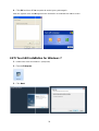
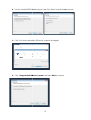
EETI TouchKit Tools Installation ........................................................................................ 17
EETI TouchKit Installation for Windows XP ................................................................. 17
EETI TouchKit Installation for Windows 7 ................................................................... 20
TouchKit Control Panel ...................................................................................................... 23
Chapter 4 24
Specifications 24
AM-1015 Specifications ..................................................................................................... 24
Chapter 5 26
Troubleshooting 26
Touch Panel Does Not Work ....................................................................................... 26
OSD Panel Cannot Work Precisely ............................................................................. 26

[鍵入文字]
C
Ch
ha
ap
pt
te
er
r
1
1
Introduction
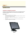
AerMonitor ( AM-
1015
A
erMonitor is a 15 inch bezel free monitor that is slim, compact,
any environment. With easy accessed on screen display controls, users can adjust brightness
and display is a compatible component and can be easily removed and installed on the FEC
AerPOS Terminal Series.
Main Features:
•
Reliable Tempered Glass ; Bezel Free Design
• The
high quality of resistive touch or durable tempered glass of projective capacitive
touch both are IP65 front panel compliant
•
Space Efficiency; Compact Size;
applications
• Various
peripheral devices support and sufficient
• Integrated
VFD and the 2
1
1015
) Introduction
erMonitor is a 15 inch bezel free monitor that is slim, compact,
bu
t tough and durable enough for
any environment. With easy accessed on screen display controls, users can adjust brightness
and display is a compatible component and can be easily removed and installed on the FEC
Reliable Tempered Glass ; Bezel Free Design
high quality of resistive touch or durable tempered glass of projective capacitive
touch both are IP65 front panel compliant
.
Space Efficiency; Compact Size;
Small Foot Print -
Fits for any kinds of POS
peripheral devices support and sufficient
I/O connectivity
VFD and the 2
nd
15” LCD display.
AM-1015
t tough and durable enough for
any environment. With easy accessed on screen display controls, users can adjust brightness
and display is a compatible component and can be easily removed and installed on the FEC
high quality of resistive touch or durable tempered glass of projective capacitive
Fits for any kinds of POS
requirements.

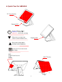
A Quick Tour for
AM
15
” Touch Display
Display OSD
Men
u item up
select, item
value increase and auto tune
Menu item down select
and item value decrease
D
isplay OSD menu and enter
Next page
MSR
Finger Print
Receiver
RFID
i
-
Button
Power Switch / Status
Blue LED:
Power ON
Red LED:
Power Off / Standby
2
AM
-1015
Display OSD
select, item
value increase and auto tune
Menu item down select
and item value decrease
isplay OSD menu and enter
15
Power Switch / Status
Power ON
Power Off / Standby
15
” 2
nd
Display

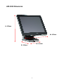
AM-1015 Dimension
H: 3
15
mm
D:
3
W:
210
mm
195mm
W: 367mm

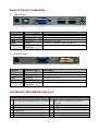
Rear I/O Panel
Connectivity
Stand Type
Bracket Type
Aer Monitor AM-
1015
I/O Port
Connector Type
DC IN
DC IN connector
USB B Type
VGA D-Sub 15
USB A Type
Line in Phone Jack
Connector
I/O Port
Connector Type
DC IN
DC IN connector
USB B Type
VGA D-Sub 15
DVI D-Sub 25
Line in Phone Jack
Connector
Standard
1
15” AM-
1015 Aer Monitor Touch Terminal
2
12V 50W Power Adaptor
3
AC Cord
4
Stand base
4
Connectivity
1015
Packing List
Connector Type
Description
DC IN connector
Connect the 12V
power adaptor to this port
Connect to touch screen
Connect LCD screen
Connect to
standard A type USB devices
Connect the Audio Devices to the
Connector Type
Description
DC IN connector
Connect the 12V
power adaptor to this port
Connect to touch screen
Connect LCD screen
Connect LCD screen
Connect the Audio Devices to the
Optional & Peripherals
1015 Aer Monitor Touch Terminal
1
MSR / RFID / Finger Print Receiver
I-Button
2
20x2 VFD / 20x2 LCM / 240x64 LCM
3 15” 2
nd
Display Bracket
power adaptor to this port
standard A type USB devices
ports
power adaptor to this port
ports
Optional & Peripherals
MSR / RFID / Finger Print Receiver
20x2 VFD / 20x2 LCM / 240x64 LCM
Display Bracket

C
Ch
ha
ap
pt
te
er
r
2
2
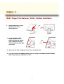
MSR / Finger Print
Reciever
1.
Remove the plastic cover
at the back of Touch
Display Module
2. Insert the MSR / RFID /
Finger Print Receiver / I-
button Module into
USB A
Type Connector. Fix the
Touch Display Module with
one screw.
3.
Make sure the USB connected and screw is fastened well.
4.
If you are looking for the detail Utility of MCR, Finger Print Reader, I
RFID Reader, please contact FEC’s
5
Reciever
/ RFID / i-Button
Installation
Remove the plastic cover
USB A
-
Touch Display Module with
Make sure the USB connected and screw is fastened well.
If you are looking for the detail Utility of MCR, Finger Print Reader, I
RFID Reader, please contact FEC’s
FAE.
Installation
If you are looking for the detail Utility of MCR, Finger Print Reader, I
-button Reader,

6
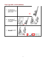
Pole Type VFD / LCM Installation
1. Assemble the 2
nd
screen with pole type
with 2 screws
2. Assemble the 2
nd
Screen with pole type
to Terminal.
3. Plug in VGA and DC
12V cables

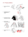
15” 2
nd
Display
Installation
1. Remove the VFD
plastic
cover
2. Assemble the 2
nd
screen
with bracket with 4
screws
3. Assemble the 2
nd
Screen
with bracket to Terminal.
4. Fasten 3 screws
(1 on top, 2 underneath)
5.
Plug in VGA and DC 12V
cables
7
Installation
plastic
screen
Screen
with bracket to Terminal.
Plug in VGA and DC 12V

15” 1
st
Touch Display
1. Release 2
thumb screw at the
back side of Display
2.
Lift the Display Module up to
disassemble from the main
unit of terminal
3.
Display and main body units
are separated.
4.
Reverse the process can
assembly back the Touch
Display Module.
** please make sure the touch
display module is firmly
connected to the docking slot
**
**Note**
During the process of disassembly and installation, please ensure the terminal is
“Power Off” and remove AC. “Hot Swap” could activate internal protection to block
touch display functionality.
8
Touch Display
Installation & Swapping
thumb screw at the
Lift the Display Module up to
disassemble from the main
Display and main body units
Reverse the process can
assembly back the Touch
** please make sure the touch
display module is firmly
connected to the docking slot
During the process of disassembly and installation, please ensure the terminal is
“Power Off” and remove AC. “Hot Swap” could activate internal protection to block
During the process of disassembly and installation, please ensure the terminal is
“Power Off” and remove AC. “Hot Swap” could activate internal protection to block

OSD Function and Adjustment
Menu Function Introduction
Menu
Function
1) AUTO SETUP
auto tune
2)BRIGHTNESS
brightness adjustment
3)CONTRAST
picture c
4)DISPLAY ADJUST
picture parameter adjustment
5)COLOR TEMPERATURE
color
6)LANGUAGE
multi
7)OSD DISPLAY
OSD parameter setup
8)VGA/DVI
VGA/DVI signal setup
9)AUDIO
audio function adjustment
10)RECALL
reset all menu item value to default setting
11)EXIT
exit OSD menu
9
OSD Function and Adjustment
OSD function and adjustment
Function
auto tune
brightness adjustment
picture c
ontrast adjustment
picture parameter adjustment
color
temperature adjustment
multi
-language setup
OSD parameter setup
VGA/DVI signal setup
audio function adjustment
reset all menu item value to default setting
exit OSD menu
Back Light Power (finger touch for
5 seconds)
Back Light Power On – Blue
LED indication
Back Light Power Off – Red
LED indication
Menu item up select, item value increase and auto
tune
Menu item down select and item value decrease
Display OSD menu and enter
Next page
5 seconds)
LED indication
LED indication
Menu item up select, item value increase and auto
Menu item down select and item value decrease

10
C
Ch
ha
ap
pt
te
er
r
3
3
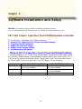
Software Installation and Setup
AM-1015 comes with a variety of drivers for different operating systems.
You can download all the necessary drivers and utilities from http://www.fecpos.com.
FEC AUO Project–Capacitive Touch Utility(Raydium controller)
FEC Projective – Capacitive Touch Utility Introduces:
1. Mode of FEC Capacitive Touch Panel and default settings
2. Capacitive Touch Sensitivity
3. Right Click Function Setting
4. Double Click Function Setting
5. F/W Reading or F/W Update
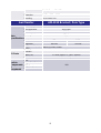
Mode of FEC P-Capacitive Touch Panel and Default Settings
The default setting of FEC P-CAP touch will be always “Mouse Mode” with Single Touch
as the factory default setting. If the application requires Multi Touch (Dual Touch), FEC P-
CAP touch can also be accordingly set as “Touch Mode” (Dual Touch with two fingers)
via Touch Utility, but it has to be in Win7 or POS Ready 7 OS environment.
Win XP, POS Ready 2009 Win7, POS Ready7
Mouse Mode Yes
No Driver Needed Yes
No Driver Needed
Touch Mode N/A Yes
No Driver Needed

11
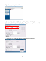
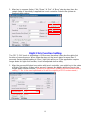
Mode setting can be done in the utility:
1. Execute the touch utility
2. Keep the Value of Vid as “8137” ; Value of Pid as “1”, then Click “Link” Button
(before it links, if it is factory default setting Mouse Mode, please keep Pid Value as “1”;
if it is set as touch mode, please make Pid Value as “3”)
3. “Connection OK”, you will see a window shows about the connection OK

12
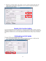
4. after the successful connection, Click “Read” button, it will show some default status
of touch utility
P-Capacitive Touch Sensitivity
The P-Capacitive Touch Sensitivity is relating to humidity of environment, humidity of
finger tips or touching area size of finger tips. Thus, if the application requires more or
less touch sensitivity, it can also be adjust by utility.
1. After the successful linked connection with touch controller, you might key in the value
to adjust the touch sensitivity. (the value is form “0” ~ “100”, “0” means the highest
sensitive “100” means the lowest sensitive) (Before the adjustment, please note the
default factory setting “20” is the most optimized to fit with the majority of POS
environments.)

13
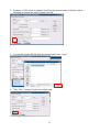
2. After key in a proper Value, Click “Erase” “Set” “Burn” step by step, then the
certain value of sensitivity is applied into touch controller. Reboot the system to
finalized utility setting.
Right Click Function Setting
The FEC P-CAP touch is simulating a USB mouse; therefore it has also the right click
function of normal mouse. When finger tip stays on the touch glass for more than 2
seconds (factory default setting is 2 sec), right click will occur. If the application require
longer times for right click function, it can be adjusted via the utility.
1. After the successful linked connection with touch controller, you might key in the value
of Right Click delay. (Value unit is second. it means the bigger value you key in, the
longer delay second it will be.) (Before the adjustment, please note the default factory
setting “2” sec is the most optimized to fit with the majority of POS environments.)

14
2. After key in a proper Value, Click “Erase” “Set” “Burn” step by step, then the
certain value of sensitivity is applied into touch controller. Reboot the System to
finalized the utility setting.
Double Click Function Setting
Due to the application and user preference, the timing of double click is always required
differently. However, FEC P-CAP touch is a simulate device as USB mouse, therefore the
sensitivity of double click can be easily adjust by default mouse utility in any of windows
OS.
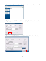
F/W Reading and F/W Update
The touch F/W can be updated by the utility.
1. F/W current Status Reading, after a successful linked connection. It will show the
touch controller F/W Version at the bottom of utility window.

15
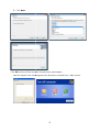
2. However, if F/W needs to update, first Click the square button (circled in red as
following) to locate the path of proper BIN file.
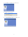
3. Choose the proper BIN file from the correct path, then “open”
4. Then Click “Connect” button for further step

16
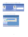
5. A new windows will pop out, please close this pop out windows and back to the utility.
6. Click “Copy” and wait for 1 minute for the new F/W applies into the controller and re-
calibration.
7. Firmware updated, Click “OK” and reboot the terminal to finalized the utility setting.
Page is loading ...
Page is loading ...
Page is loading ...
Page is loading ...
Page is loading ...
Page is loading ...
Page is loading ...
Page is loading ...
Page is loading ...
Page is loading ...
Page is loading ...
-
 1
1
-
 2
2
-
 3
3
-
 4
4
-
 5
5
-
 6
6
-
 7
7
-
 8
8
-
 9
9
-
 10
10
-
 11
11
-
 12
12
-
 13
13
-
 14
14
-
 15
15
-
 16
16
-
 17
17
-
 18
18
-
 19
19
-
 20
20
-
 21
21
-
 22
22
-
 23
23
-
 24
24
-
 25
25
-
 26
26
-
 27
27
-
 28
28
-
 29
29
-
 30
30
-
 31
31


Firich Enterprise AM-1015 User manual
- Category
- POS terminals
- Type
- User manual
Ask a question and I''ll find the answer in the document
Finding information in a document is now easier with AI


