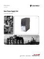
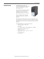
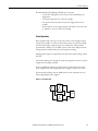
Allen-Bradley 1606-XLB is a robust power supply with a power reserve to start demanding loads. Despite its compact size, it is a reliable choice for extreme environmental conditions and global use. Additionaly, it comes with a DC-OK signal, which makes it ideal for preventive function monitoring and avoiding long downtimes.
Allen-Bradley 1606-XLB is a robust power supply with a power reserve to start demanding loads. Despite its compact size, it is a reliable choice for extreme environmental conditions and global use. Additionaly, it comes with a DC-OK signal, which makes it ideal for preventive function monitoring and avoiding long downtimes.


-
 1
1
-
 2
2
-
 3
3
-
 4
4
-
 5
5
-
 6
6
-
 7
7
-
 8
8
-
 9
9
-
 10
10
-
 11
11
-
 12
12
-
 13
13
-
 14
14
-
 15
15
-
 16
16
-
 17
17
-
 18
18
-
 19
19
-
 20
20
-
 21
21
-
 22
22
-
 23
23
-
 24
24
-
 25
25
-
 26
26


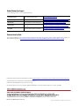
Allen-Bradley 1606-XLB Reference guide
- Type
- Reference guide
- This manual is also suitable for
Allen-Bradley 1606-XLB is a robust power supply with a power reserve to start demanding loads. Despite its compact size, it is a reliable choice for extreme environmental conditions and global use. Additionaly, it comes with a DC-OK signal, which makes it ideal for preventive function monitoring and avoiding long downtimes.
Ask a question and I''ll find the answer in the document
Finding information in a document is now easier with AI
Related papers
-
Allen-Bradley Bulletin 1606 Reference guide
-
-
-
Allen-Bradley 2099-BM09-S User manual
-
Allen-Bradley Kinetix 2198-H015-ERS2 User manual
-
-
-
-
-
Other documents
-
 Rockwell Automation Allen-Bradley 1606-XLS960E Reference guide
-
 Rockwell Automation Allen-Bradley 1606-XLP60EQ Reference guide
-
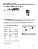 Rockwell Automation 1606-XLE240EP User manual
-
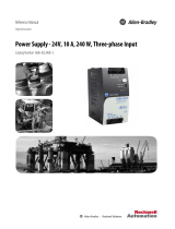 Rockwell Automation Allen-Bradley 1606-XLE240E-3 Reference guide
-
MULTISPAN PS24-5A Owner's manual
-
 Rockwell Automation Allen-Bradley 1606-XLSCAP24-6 Reference guide
-
 Rockwell Automation 1606-XLS180B User manual
-
Ubiquiti Networks POE-15V Datasheet
-
 Rockwell Automation Allen-Bradley 1606-XLSBUFFER24 Reference guide
-
Maxwell MAFH036E2 Warranty


