Page is loading ...

1 EN Instruction Manual DC Power Supply
2 DE Bedienungsanleitung DC Stromversorgung
3 FR Manual d'instructions DC Alimentation d'Énergie
4 ES Manual de instrucciones DC Fuente De Alimentación
5 IT Manuale di Istruzione DC Gruppo di alimentazione
6 PT Manual de Instruções DC Fonte De Alimentação
1606-XLS120E
Read first ! English
1
Before operating this unit please read this manual thoroughly. Retain this manual for future reference! The power supply may only installed and put into operation by qualified personnel.
Intended Use:
This device is designed for installation in an enclosure and is intended for the general use such as in industrial control, office, communication, and instrumentation equipment. Do not use this device in
aircrafts, trains and nuclear equipment where malfunction of the power supply may cause severe personal injury or threaten human life.
WARNING !
CAUTION !
Risk of electrical shock, fire, personal injury or death.
(1) Do not use the unit without proper grounding (Protective earth)
(2) Turn power off before working on the power supply. Protect against inadvertent
repowering.
(3) Make sure of the wiring is correct by following all local and national codes.
(4) Do not modify or repair the unit.
(5) Do not open the unit as high voltages are present inside.
(6) Use caution to prevent any foreign objects from entering into the housing.
(7) Do not use in wet locations.
(8) Do not use the unit in area where moisture or condensation can be expected
Deration in output power may be necessary when:
(1) minimum installation clearance can not be met
(2) altitudes higher than 2000m
(3) power supply is used above 60°C ambient
(4) mounting orientation is other than input terminal located at the bottom and output at the top.
(5) airflow for convection cooling is obstructed
Details for de-rating can be found in this manual.
Do not touch during power-on, and immediately after power-off. Hot surface may cause heat injury.
The unit does not contain a service parts. The tripping of an internal fuse is caused by an internal
defect. If damage or malfunction should occur during operation, immediately turn power off and send
unit for inspection to the factory!
The information presented in this document is believed to be accurate and reliable and may change without notice. The English text applies in cases of doubt.
Notes for use in
hazardous locations
WARNING EXPLOSION HAZARDS
Units which are marked with "Class I Div 2" are suitable for use in non-hazardous or Class I Division 2 Groups A, B, C, D locations only.
Substitution of components may impair suitability for Class I Division 2 environment. Do not disconnect equipment unless power has been switched off.
Wiring must be in accordance with Class I, Division 2 wiring methods of the National Electrical Code, NFPA 70, and in accordance with other local or national codes.
Vor Inbetriebnahme lesen ! Deutsch
2
Bitte lesen Sie diese Warnungen und Hinweise sorgfältig durch bevor Sie die Stromversorgung in Betrieb nehmen. Bewahren Sie die Anleitung zum Nachlesen auf. Die Stromversorgung darf nur
durch fachkundiges und qualifiziertes Personal installiert werden.
Bestimmungsgemäßer Gebrauch:
Dieses Gerät ist für den Einbau in ein Gehäuse konzipiert und zur Verwendung für allgemeine elektronische Geräte, wie z.B. Industriesteuerungen, Bürogeräte, Kommunikationsgeräte oder
Messgeräte geeignet. Benutzen Sie dieses Gerät nicht in Steuerungsanlagen von Flugzeugen, Zügen oder atomaren Einrichtungen, in denen eine Funktionsstörung zu schweren Verletzungen führen
oder Lebensgefahr bedeuten kann.
WARNUNG !
VORSICHT !
Missachtung nachfolgender Punkte kann einen elektrischen Schlag, Brände, schwere Unfälle
oder Tod zur Folge haben.
(1) Betreiben Sie die Stromversorgung nie ohne Schutzleiter!
(2) Schalten Sie die Netzspannung vor Installations-, Wartungs- oder Änderungsarbeiten ab
und sichern Sie gegen unbeabsichtigtes Wiedereinschalten.
(3) Sorgen Sie für eine ordnungsgemäße und fachgerechte Verdrahtung.
(4) Führen Sie keine Änderungen oder Reparaturversuche am Gerät durch.
(5) Gerät niemals öffnen. Im Inneren befinden sich gefährliche Spannungen.
(6) Verhindern Sie das Eindringen von Fremdkörpern, wie z.B. Büroklammern und anderen
Metallteilen.
(7) Betreiben Sie das Gerät nicht in feuchter Umgebung.
(8) Betreiben Sie das Gerät nicht in einer Umgebung, bei der mit Betauung oder
Kondensation zu rechnen ist.
Rücknahme der Ausgangsleistung kann erforderlich sein:
(1) wenn die minimalen Einbauabstände nicht eingehalten werden können.
(2) bei Aufstellhöhen über 2000m.
(3) Betrieb bei Umgebungstemperaturen über 60°C.
(4) bei Einbaulagen abweichend von der Standardeinbaulage (Eingang unten, Ausgang oben).
(5) bei behinderter Luftzirkulation.
Weitere Informationen zur Leistungsrücknahme befinden sich in dieser Betriebsanleitung.
Gehäuse nicht während des Betriebes oder kurz nach dem Abschalten berühren. Heiße Oberflächen
können Verletzungen verursachen.
Das Gerät beinhaltet keine Servicebauteile. Interne Sicherungen lösen nur bei Gerätedefekt aus. Bei
Funktionsstörungen oder Beschädigungen schalten Sie sofort die Versorgungsspannung ab und
senden das Gerät zur Überprüfung ins Werk.
Die angegebenen Daten dienen allein der Produktbeschreibung und sind nicht als zugesicherte Eigenschaften im Rechtssinne aufzufassen. Im Zweifelsfall gilt der englische Text
Hinweise für den
Betrieb in
explosionsgefährdeter
Umgebung
ACHTUNG EXPLOSIONSGEFAHR !
Geräte die am Leistungsschild mit "Class I Div 2" gekennzeichnet sind, sind für den Einsatz in Klasse I Division 2 Gruppen A,B,C,D oder für explosions-ungefährliche
Aufstellorte geeignet. Veränderungen an Bauteilen können die Tauglichkeit für Klasse I Division 2 beeinträchtigen. Anschlüsse nicht trennen solange Spannung anliegt.
Anschluss muss unter Berücksichtigung der Anforderungen nach Klasse I Division 2 Artikel 501-4(b) des National Electrical Code, NFPA 70 erfolgen.
Français
3
Merci de lire ces instructions de montage et d'entretien avant de mettre l'alimentation sous tension. Conservez ce manuel qui vous sera toujours utile. Cette alimentation doit être installée par du
personnel qualifié et compétent.
Utilisation:
Cet appareil est conçu pour être installé dans une armoire et pour tous les équipements électroniques, tel que l'équipement industriel de commande, l'équipement de bureau, le matériel de
communication et les instruments de mesures. N'utilisez pas cet appareil pour l'équipement de commandes dans les avions, les trains et l'équipement atomique où un problème de fonctionnement
de l'alimentation pourrait causer des blessures graves ou menacer la vie humaine.
ATTENTION !
ATTENTION !
Prendre en compte les points suivants, afin d'éviter toute détérioration électrique, incendie,
dommage aux personnes ou mort.
(1) ne jamais faire fonctionner l'alimentation sans raccordement à la terre !
(2) débrancher l'installation avant toute intervention sur l'alimentation (ou démontage) et
s'assurer qu'il n'y a pas risque de redémarrage.
(3) s'assurer que le câblage a été fait selon les prescriptions
(4) ne pas effectuer de réparations ou modifications sur l'alimentation
(5) ne pas ouvrir l'appareil. Des tensions importantes passent à l'intérieur.
(6) veiller à ce qu'aucun objet ne rentre en contact avec l'intérieur de l'alimentation
(trombonnes, pièces métalliques)
(7) ne pas faire fonctionner l'appareil dans un environnement humide ou à l'extérieur, non
protégé
(8) ne pas utiliser l'appareil dans un environnement où il peut y avoir de la condensation.
Des limitations de puissance de sortie peuvent apparaïtre si :
(1) les distances d'installation mini. ne peuvent être observées
(2) installation à une altitude > 2000 m
(3) pour des fonctionnements en charge et avec une température ambiante > 60°C
(4) pour des positions de montage différentes de la préconisation standard (entrée dessous, sortie en
haut)
(5) lorsque la circulation d'air est génêe
D'autres informations sont disponibles dans la documentation de mise en service "
Le déclenchment du fusible interne traduit très probablement un défaut au niveau de l'appareil. Si un
défaut quelconque apparaît en cours de fonctionnement, débrancher au plus vite l'alimentation. Dans
ce deux cas de figure, il convient de faire contrôler l'alimentation en usine!
Les données indiquées dans ce document servent uniquement à donner une description du produit et n'ont aucune valeur juridique. En cas de divergences, le texte anglais fait foi.
Utilisation
Class I Div 2
ATTENTION RISQUE D’ EXPLOSION Les appareils portant la marque ‘Class I Div 2’ au niveau de la plaque signalétique sont prévus pour fonctionner en Classe I, Division
2, Groupes A,B,C,D ou pour un environnement non explosif et non dangereux.
Le remplacement de composants peut rendre le matériel impropre à une utilisation en Classe 1, Division 2.
Ne déconnecter l’équipement qu’ hors tension ou en zone connue comme non dangereuse.
Le raccordement doit obligatoirement tenir compte des exigences de la classe 1, division 2, article 501-4(b) du National Electrical Code, NFPA 70.

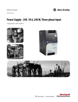
1606-XLS120E Power Supply Instruction Manual
Technical Data
1606-XLS120E
Output Voltage
DC 24-28V
externally adjustable
Factory Set
typ. 24.1V at full rated load
Output Current
min 5-4.5A continuous
min 7.5-6.7A for typ. 4 sec
Output Power
min. 120W continuous
min. 180W for typ. 4 sec
Output Ripple
max. 50mVpp BW DC to 20MHz
Over-voltage Protection
max. 36Vdc
AC Input Voltage
-
AC 100-240V -15/+10%, 50-60Hz
TN, TT and IT mains
AC Input Current
max. 1.4-0.65A at 100-240Vac
DC Input
- DC 110-300V -20/+20%
DC Input Current
max. 1.2-0.45A at 110 - 300Vdc
Power Factor
typ. 0.99-0.91 at 100 - 230Vac
AC Inrush Current
max. 15A peak, 1A
2
s at 100 - 230Vac
Efficiency
typ. 91.6 / 92.7% at 120 / 230Vac
Losses
typ. 11.0 / 9.4W at 120 / 230Vac
Hold-up Time
typ. 33 / 59ms at 120 / 230Vac
Capacitive Loads
- no limitations
Inductive Loads
- no limitations
Limited Warranty
- 1 year from date of purchase
Environment
Protection
Operational temperature
-25 to +70°C De-rate above +60°C
Output
Overload, no-load, short-circuit proof
Storage temperature
-40 to +85° C Storage, transport
Degree of protection
IP 20 EN/IEC 60529
Humidity
5 to 95% RH No condensation allowed
Class of protection
I PE (Ground) connection required!
Vibration sinusoidal
2g IEC 60068-2-6
Degree of pollution
2 EN 50178, not conductive
Shock
15g 6ms, 10g 11ms IEC 60068-2-27
Over-temperature protection
yes Output shut-down with automatic restart
Output over-voltage protection
yes Output shut-down with automatic restart
Over-voltage category
III EN 50178
Penetration protection
>3.5mm e.g. screws, small parts …
Internal input fuse
T3.15A
Device protection, not externally
accessible
Allowed output current versus
the ambient temperature
Ambient temperature is defined
2cm below the unit.
0%
25%
50%
75%
100%
125%
150%
-40°C -20°C 0°C 20°C 40°C 60°C 80°C
Ambient Temperature
for typ. 4s
continuous
External fuse on input Choose value according to the steady state input
current, if needed for branch circuit protection.
Functional Diagram
Dielectric Strength
Type tests and factory tests:
Conducted by the manufacturer.
Do not repeat test in field!
Field test rules:
(1) Use appropriate test equipment which
apply the voltage with a slow ramp!
(2) Connect L and N together as well as all
output poles.
(3) Use only AC test-voltages with 50/60Hz.
The output voltage is floating and has no ohmic
reference to ground.
A D
C
B
B
N
L
Input DC-ok
Earth
Output
-
+
A B C D
Type Test
60s 2500Vac 3000Vac 500Vac 500Vac
Factory Test
5s 2500Vac 2500Vac 500Vac 500Vac
+
+
-
-
V
OUT
DC
ok
Output
Over-
Voltage
Protection
PFC
Converter
Input Fuse
Input Filter
Input Rectifier
Inrush Limiter
Transient Filter
Output
Voltage
Regulator
Power
Converter
Output
Filter
DC ok
Relay
Output
Voltage
Monitor
Output
Power
Manager
Temper-
ature
Shut-
down
Over-
load
DC
ok
L
N
Field Test
5s 2000Vac 2000Vac 500Vac 500Vac
Overload Behaviour
The unit is designed to support loads with a higher short-term
power requirement without damage or shutdown.
0V
4V
8V
12V
16V
20V
24V
28V
0A 2A 4A 6A 8A 10A 12A
continuous
for 4s
Output Current
0s
2s
4s
6s
8s
10s
110% 120% 130% 140% 150% 160%
Output Current
min.
max.
Output characteristic (typ.)
Curve is valid for the 24V unit. Units with
output voltages other than 24V have an
equivalent and proportional behaviour.
Bonus time
Duration until the output starts dipping. Bonus
Time is hardware controlled.
Repetitive pulse loading: Multiple pulses can be supported as long as the average (R.M.S.)
output current stays below the specified continuous output current. If it is higher, the unit will
respond with a thermal shut-down.
Examples for pulse load
compatibility:
P
PEAK
P
0
T
PEAK
T
0
180W 120W 1s >25s
180W 0W 1s >1.3s
180W 60W 0.1s >0.16s
180W 60W 1s >1.6s
DC-ok Relay Contact
This feature monitors the output voltage, which is produced by the power supply, and is
independent of a return voltage from a unit which is connected in parallel.
Contact closes as soon as the output voltage reaches the nominal value.
Contact opens as soon as the output voltage dips more than 10%.
Short dips will be extended to a length of 250ms on the relay.
Dips shorter than 1ms will be ignored.
Contact ratings 60Vdc 0.3A, 30Vdc 1A, 30Vac 0.5A, resistive load
250ms
90%
V
ADJ
V
ADJ
closed
open
> 1ms< 1ms
10%
open
closed
V
OUT
Please note:
The DC-ok feature requires that the output voltage reach the nominal (=adjusted) level after
turn-on in order to function to specification. If this level cannot be achieved, the unit will show
an overload condition. The overload signal will disappear as soon as the adjusted voltage is
reached. This is an important to condition to consider particularly, if the load is a battery or
the power supply is used for N+1 redundant systems.
t
100%
P
PEAK
0%
T
PEAK
P
0
T
0
P
OUT
max.
150%
t
180W 60W 3s >4.9s

1606-XLS120E Power Supply Instruction Manual
Safety
Separation of output
SELV IEC/EN 60950-1
EMC
The device is suitable for applications in industrial environment as well as in residential,
commercial and light industry environment without any restrictions.
For further details see datasheet.
PELV EN 60204-1, EN 50178, IEC 60364-4-41
EMC Immunity
EN 61000-6-1, EN 61000-6-2
Touch current
max. 0.4mA Earth leakages current, TN- mains
Isolation resistance
min. 5MOhm Input to output, 500Vdc
EMC Emission EN 61000-3-2, EN 61000-3-3, EN 61000-6-3, EN 61000-6-4,
FCC Part 15 Class B
PE resistance
max. 0.1Ohm Between housing and ground terminal
Transformer
Safety transformer according to IEC/EN 61558-2-17
This device complies with FCC Part 15 rules. Operation is subjected to following two
conditions: (1) this device may not cause harmful interference, and (2) this device must
accept any interference received, including interference that may cause undesired operation.
Approvals
See datasheet or markings on the unit
CE mark in conformance with EMC guideline 89/336/EEC and 93/68/EEC and low-voltage directive (LVD) 73/23/EWG.
Terminals and Connections
Terminals Input Output DC-ok
Type
Bi-stable, quick-connect spring clamp terminals
Ferrules
Allowed, but not required
Solid wire
0.5-6mm
2
0.3-4mm
2
0.3-4mm
2
Stranded wire
0.5-4mm
2
0.3-2.5mm
2
0.3-2.5mm
2
AWG
AWG 20-10 AWG 28-12 AWG 28-12
Stripping length
10mm / 0.4inch 6mm / 0.25inch 6mm / 0.25inch
Pull-out force
10AWG:80N, 12AWG:60N, 14AWG:50N, 16AWG:40N (UL486E)
1. Insert the wire 2. Snap the lever
Use appropriate copper cables that are designed for an operating temperatures of 60°C (for ambient
up to 45°C) and 75°C (for ambient up to 60°C), minimum. Follow national installation codes and
regulations! Ensure that all strands of a stranded wire enter the terminal connection! Up to two
stranded wires with the same cross section are permitted in one connection point (except PE wire). Do
not use without PE (Ground) connection!
Physical Dimensions, Indicators and Cooling
Width
40mm / 1.57’’
Height
124mm / 4.88’’
Depth
117mm / 4.61’’ Plus DIN-rail depth
Weight
620g / 1.37lb
DIN-Rail
Use DIN-rails according to EN 60715 or EN 50022
with a height of 7.5 or 15mm
Mounting
Orientation
Input terminal on top and output terminals on the bottom.
For other orientations consult factory.
Indicators
DC-ok LED
(green)
Overload
lamp (red)
DC-ok
Relay
Normal operating mode
ON OFF Closed
BonusPower
®
operation
ON OFF Closed
Overload (V
OUT
< 90%)
OFF ON Open
Short-circuit (V
OUT
= 0)
OFF ON Open
Temperature shut-down
OFF Flashing Open
No input power
OFF OFF Open
Do not obstruct air flow! The unit is convection cooled. Ventilation grid must be kept free of any obstructions.
Keep installation clearances at higher ambient temperature and full load:
60mm on top and on the bottom, 15mm on the left and right side
PU-348.010.38-10A
Operation on Two Phases
240V max.
Fuse
DC
L
N
PE
N
L2
Center
Tap
L1
L3
(1) The rated supply voltage must be below
240V.
(2) Use an appropriate fuse to protect the N
terminal!
Parallel Operation
Power Supply A
Power Supply B
-
AC
DC
+
-
AC
DC
+
Load
+
-
Fuse
*)
Fuse
*)
(1) Power supplies can be paralleled to
increase output power or to build redundant
systems.
(2) For parallel operation use power supplies
of the same family.
(3) Use load connection wires of the same
gauge and length.
(4) Set the output voltages of all power
supplies to the same value.
(5) A fuse is only required if more than three
units are connected in parallel.
Serial Operation
Load
Power Supply A
Power Supply B
+
-
AC
DC
+
-
AC
DC
+
-
Earth
*)
(1) It is possible to connect as many units in
series as needed, providing the sum of the
voltage does not exceed 150Vdc.
(2) For serial operation use power supplies
of the same type.
(3) Grounding of the output is required when
the sum of the output voltage exceeds
60Vdc.
Operation with DC Input
Fuse
+
-
Load
+
-
DC
L
N
PE
AC
+
-
(1) The power supply will operate with a DC
input voltage.
(2) Use a battery or similar DC source.
(3) Connect +pole to L and –pole to N
(4) In case the –pole of the battery is not
grounded, use an appropriate fuse to protect
the N terminal.
(5) Connect the ground terminal of the power
supply to a PE wire or to machine ground.
Check touch current (earth leakage current)! The total touch current is the sum of
the touch currents of all units. Safety limits – depending on the field of application
- apply for the allowed touch current!
open
close
Air flow
/