Specifications
Specifications are subject to change without notice.
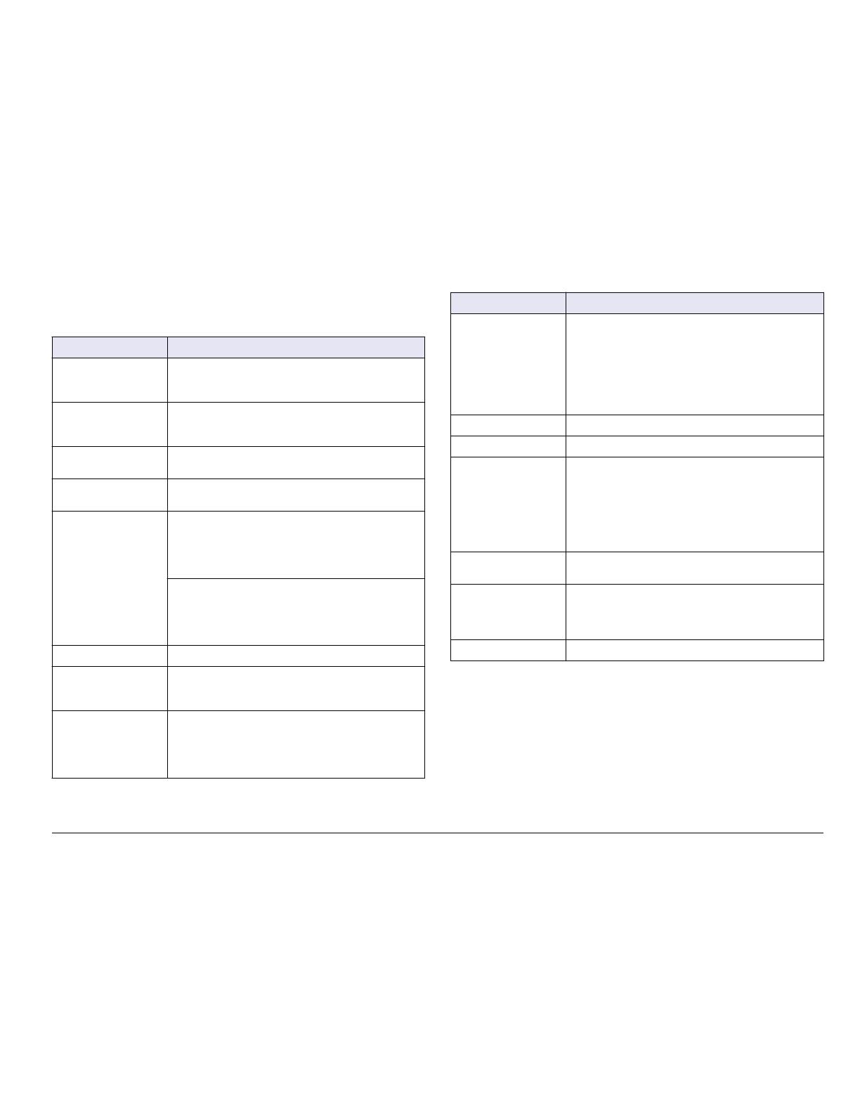
Specification Details
Component description Microprocessor-controlled and menu-driven controller
that operates the sensor and displays measured
values.
Operating temperature -20 to 60 C (-4 to 140 F); 95% relative humidity, non-
condensing with sensor load <7 W; -20 to 50 C (-4 to
104 F) with sensor load <28 W
Storage temperature -20 to 70 C (-4 to 158 F); 95% relative humidity, non-
condensing
Enclosure
1
NEMA 4X/IP66 metal enclosure with a corrosion-
resistant finish
Power requirements AC powered controller: 100-240 VAC ±10%,
50/60 Hz; Power 50 VA with 7 W sensor/network
module load, 100 VA with 28 W sensor/network
module load (optional Modbus, RS232/RS485,
Profibus DPV1 or HART network connection).
24 VDC powered controller: 24 VDC—15%, + 20%;
Power 15 W with 7 W sensor/network module load,
40 W with 28 W sensor/network module load (optional
Modbus, RS232/RS485, Profibus DPV1 or HART
network connection).
Altitude requirements Standard 2000 m (6562 ft) ASL (Above Sea Level)
Pollution
degree/Installation
category
Polution Degree 2; Installation Category II
Outputs Two analog (0-20 mA or 4-20 mA) outputs. Each
analog output can be assigned to represent a
measured parameter such as pH, temperature, flow or
calculated values. Optional module supplies three
additional analog outputs (5 total).
Specification Details
Relays Four SPDT, user-configured contacts, rated 250 VAC,
5 Amp resistive maximum for the AC powered
controller and 24 VDC, 5A resistive maximum for the
DC powered controller. Relays are designed for
connection to AC Mains circuits (i.e., whenever the
controller is operated with 115 - 240 VAC power) or DC
circuits (i.e., whenever the controller is operated with
24 VDC power).
Dimensions ½ DIN—144 x 144 x 180.9 mm (5.7 x 5.7 x 7.12 in.)
Weight 1.7 kg (3.75 lb)
Compliance
information
2
CE approved (with all sensor types). Listed for use in
general locations to UL and CSA safety standards by
ETL (with all sensor types).
Certain AC mains powered models are listed for use in
general safety locations to UL and CSA safety
standards by Underwriters Laboratories (with all sensor
types).
Digital communication Optional Modbus, RS232/RS485, Profibus DPV1 or
HART network connection for data transmission
Data logging Secure Digital Card (32 GB maximum) or special
RS232 cable connector for data logging and
performing software updates. The controller will keep
approximately 20,000 data points per sensor.
Warranty 2 years
1
Units that have the Underwriters Laboratories (UL) certification are intended
for indoor use only and do not have a NEMA 4X/IP66 rating.
2
DC powered units are not listed by UL.
General information
In no event will the manufacturer be liable for direct, indirect, special,
incidental or consequential damages resulting from any defect or
omission in this manual. The manufacturer reserves the right to make
changes in this manual and the products it describes at any time, without
(nglisK 5


