Hach SC200 User manual
- Category
- Measuring, testing & control
- Type
- User manual

DOC023.53.80040
sc200 Controller
07/2016, Edition 8
User Manual


Table of Contents
Specifications.............................................................................................................. 3
General information.................................................................................................. 3
Safety information........................................................................................................ 4
Use of hazard information.................................................................................... 4
Precautionary labels............................................................................................. 4
Certification........................................................................................................... 4
Product overview......................................................................................................... 5
Sensors and sensor modules............................................................................... 6
Relays outputs and signals................................................................................... 6
Device scans........................................................................................................ 6
Controller enclosure............................................................................................. 6
Controller mounting options.................................................................................. 6
Installation..................................................................................................................... 7
Mounting components and dimensions....................................................................... 7
Controller mounting..................................................................................................... 8
High-voltage barrier................................................................................................... 11
Electrostatic discharge (ESD) considerations............................................................ 11
Wiring overview......................................................................................................... 12
Wiring for power......................................................................................................... 12
Alarms and relays...................................................................................................... 15
Wiring relays.............................................................................................................. 15
Analog output connections........................................................................................ 17
Discrete input wiring connections.............................................................................. 18
Connect a digital sc sensor........................................................................................ 20
Connect the optional digital communication output................................................... 21
Install a Secure Digital (SD) memory card ................................................................ 21
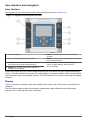
User interface and navigation............................................................................ 22
User interface............................................................................................................ 22
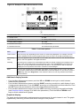
Display....................................................................................................................... 22
Additional display formats................................................................................... 23
Graphical display................................................................................................ 23
System startup.......................................................................................................... 24
Set the language, date and time for the first time ..................................................... 24
Controller configuration information........................................................................... 24
Advanced operation................................................................................................ 25
Security setup............................................................................................................ 25
Enable or disable the passcode......................................................................... 25
Edit the passcode............................................................................................... 25
Protect features.................................................................................................. 26
Configure a 4-20 mA input module............................................................................ 26
Configure a 4-20 mA output module.......................................................................... 27
Configure the controller analog outputs..................................................................... 27
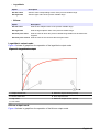
Logarithmic output mode ................................................................................... 29
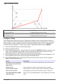
Bilinear output mode........................................................................................... 29
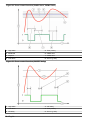
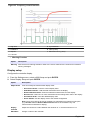
Configure relays......................................................................................................... 30
1

Display setup............................................................................................................. 39
Update the date and time.......................................................................................... 40
Set the datalog mode and interval............................................................................. 40
Set up a calculation................................................................................................... 40
Set up the discrete inputs.......................................................................................... 41
Update the display language..................................................................................... 42
Using the secure digital memory (SD) card............................................................... 42
Updating software............................................................................................... 42
Saving data and event logs with SD cards......................................................... 43
Access data and event log files on the SD card................................................. 43
Firmware updates with SD cards........................................................................ 44
Backup settings to an SD card........................................................................... 44
Restore settings to the controller........................................................................ 44
Transfer settings to another device.................................................................... 45
Using the service port................................................................................................ 45
Using DataCom......................................................................................................... 45
Maintenance............................................................................................................... 46
Cleaning the controller............................................................................................... 46
Fuse replacement...................................................................................................... 46
Battery replacement................................................................................................... 46
Troubleshooting....................................................................................................... 46
Test and Maintenance menu..................................................................................... 48
Warning and error conditions..................................................................................... 49
Device scan information ...................................................................................... 50
Replacement parts and accessories............................................................... 50
Table of Contents
2

Specifications
Specifications are subject to change without notice.
Specification Details
Component description Microprocessor-controlled and menu-driven controller that operates the sensor and
displays measured values.
Operating temperature -20 to 60 ºC (-4 to 140 ºF); 95% relative humidity, non-condensing with sensor load
<7 W; -20 to 50 ºC (-4 to 104 ºF) with sensor load <28 W
Storage temperature -20 to 70 ºC (-4 to 158 ºF); 95% relative humidity, non-condensing
Enclosure
1
NEMA 4X/IP66 metal enclosure with a corrosion-resistant finish
Power requirements AC powered controller: 100-240 VAC ±10%, 50/60 Hz; Power 50 VA with 7 W
sensor/network module load, 100 VA with 28 W sensor/network module load
(optional Modbus, RS232/RS485, Profibus DPV1 or HART network connection).
24 VDC powered controller: 24 VDC—15%, + 20%; Power 15 W with 7 W
sensor/network module load, 40 W with 28 W sensor/network module load (optional
Modbus, RS232/RS485, Profibus DPV1 or HART network connection).
Altitude requirements Standard 2000 m (6562 ft) ASL (Above Sea Level)
Pollution
degree/Installation
category
Polution Degree 2; Installation Category II
Outputs Two analog (0-20 mA or 4-20 mA) outputs. Each analog output can be assigned to
represent a measured parameter such as pH, temperature, flow or calculated
values. Optional module supplies three additional analog outputs (5 total).
Relays Four SPDT, user-configured contacts, rated 250 VAC, 5 Amp resistive maximum for
the AC powered controller and 24 VDC, 5A resistive maximum for the DC powered
controller. Relays are designed for connection to AC Mains circuits (i.e., whenever
the controller is operated with 115 - 240 VAC power) or DC circuits (i.e., whenever
the controller is operated with 24 VDC power).
Dimensions ½ DIN—144 x 144 x 180.9 mm (5.7 x 5.7 x 7.12 in.)
Weight 1.7 kg (3.75 lb)
Compliance information
2
CE approved (with all sensor types). Listed for use in general locations to UL and
CSA safety standards by ETL (with all sensor types).
Certain AC mains powered models are listed for use in general safety locations to
UL and CSA safety standards by Underwriters Laboratories (with all sensor types).
Digital communication Optional Modbus, RS232/RS485, Profibus DPV1 or HART network connection for
data transmission
Data logging Secure Digital Card (32 GB maximum) or special RS232 cable connector for data
logging and performing software updates. The controller will keep approximately
20,000 data points per sensor.
Warranty 2 years
General information
In no event will the manufacturer be liable for direct, indirect, special, incidental or consequential
damages resulting from any defect or omission in this manual. The manufacturer reserves the right to
1
Units that have the Underwriters Laboratories (UL) certification are intended for indoor use only
and do not have a NEMA 4X/IP66 rating.
2
DC powered units are not listed by UL.
English 3

make changes in this manual and the products it describes at any time, without notice or obligation.
Revised editions are found on the manufacturer’s website.
Safety information
N O T I C E
The manufacturer is not responsible for any damages due to misapplication or misuse of this product including,
without limitation, direct, incidental and consequential damages, and disclaims such damages to the full extent
permitted under applicable law. The user is solely responsible to identify critical application risks and install
appropriate mechanisms to protect processes during a possible equipment malfunction.
Please read this entire manual before unpacking, setting up or operating this equipment. Pay
attention to all danger and caution statements. Failure to do so could result in serious injury to the
operator or damage to the equipment.
Make sure that the protection provided by this equipment is not impaired. Do not use or install this
equipment in any manner other than that specified in this manual.
Use of hazard information
D A N G E R
Indicates a potentially or imminently hazardous situation which, if not avoided, will result in death or serious injury.
W A R N I N G
Indicates a potentially or imminently hazardous situation which, if not avoided, could result in death or serious
injury.
C A U T I O N
Indicates a potentially hazardous situation that may result in minor or moderate injury.
N O T I C E
Indicates a situation which, if not avoided, may cause damage to the instrument. Information that requires special
emphasis.
Precautionary labels
Read all labels and tags attached to the instrument. Personal injury or damage to the instrument
could occur if not observed. A symbol on the instrument is referenced in the manual with a
precautionary statement.
This symbol, if noted on the instrument, references the instruction manual for operation and/or safety
information.
This symbol indicates that a risk of electrical shock and/or electrocution exists.
This symbol indicates the presence of devices sensitive to Electro-static Discharge (ESD) and
indicates that care must be taken to prevent damage with the equipment.
Electrical equipment marked with this symbol may not be disposed of in European domestic or public
disposal systems. Return old or end-of-life equipment to the manufacturer for disposal at no charge to
the user.
Certification
Canadian Radio Interference-Causing Equipment Regulation, IECS-003, Class A:
4
English

Supporting test records reside with the manufacturer.
This Class A digital apparatus meets all requirements of the Canadian Interference-Causing
Equipment Regulations.
Cet appareil numérique de classe A répond à toutes les exigences de la réglementation canadienne
sur les équipements provoquant des interférences.
FCC Part 15, Class "A" Limits
Supporting test records reside with the manufacturer. The device complies with Part 15 of the FCC
Rules. Operation is subject to the following conditions:
1. The equipment may not cause harmful interference.
2. The equipment must accept any interference received, including interference that may cause
undesired operation.
Changes or modifications to this equipment not expressly approved by the party responsible for
compliance could void the user's authority to operate the equipment. This equipment has been tested
and found to comply with the limits for a Class A digital device, pursuant to Part 15 of the FCC rules.
These limits are designed to provide reasonable protection against harmful interference when the
equipment is operated in a commercial environment. This equipment generates, uses and can
radiate radio frequency energy and, if not installed and used in accordance with the instruction
manual, may cause harmful interference to radio communications. Operation of this equipment in a
residential area is likely to cause harmful interference, in which case the user will be required to
correct the interference at their expense. The following techniques can be used to reduce
interference problems:
1. Disconnect the equipment from its power source to verify that it is or is not the source of the
interference.
2. If the equipment is connected to the same outlet as the device experiencing interference, connect
the equipment to a different outlet.
3. Move the equipment away from the device receiving the interference.
4. Reposition the receiving antenna for the device receiving the interference.
5. Try combinations of the above.
Product overview
The controller displays sensor measurements and other data, can transmit analog and digital signals,
and can interact with and control other devices through outputs and relays. Outputs, relays, sensors
and sensor modules are configured and calibrated through the user interface on the front of the
controller.
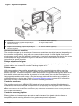
Figure 1 shows the product components. Components may vary according to controller configuration.
Contact the manufacturer if parts are damaged or missing.
English
5

Figure 1 System components
1 Controller 4 Network module (optional)
2 Strain relief assembly (optional depending on
controller version)
5 High-voltage barrier
3 Digital connection fitting (optional depending on
controller version)
6 Sensor modules (optional)
Sensors and sensor modules
The controller accepts up to a maximum of two sensor modules or two digital sensors (depending on
the controller configuration), along with one communication module. A single digital sensor and a
single sensor module can be installed in combination. A variety of sensors can be wired to the sensor
modules. Sensor wiring information is given in the specific sensor manuals and in the user
instructions for specific modules.
Relays outputs and signals
The controller has four configurable relay switches and two analog outputs. An optional analog
output module can increase the number of analog outputs to five.
Device scans
With two exceptions, the controller automatically scans for connected devices without user input
when it is powered on. The first exception is when the controller is powered on for the first time
before initial use. The second exception is after the controller configuration settings have been set to
their default values and the controller is powered on. In both cases, the controller first displays the
language, date and time edit screens. After the language, date and time entries are accepted, the
controller performs a device scan. Refer to Connect a digital sc sensor on page 20 for instructions
about how to scan for devices when the controller is already powered on.
Controller enclosure
The controller enclosure is NEMA 4X/IP66-rated and has a corrosion-resistant finish designed to
withstand corrosive environmental constituents such as salt spray and hydrogen sulfide. Protection
against environmental damage is strongly recommended for outdoor use.
Note: Units that have the Underwriters Laboratories (UL) certification are intended for indoor use only and do not
have a NEMA 4X/IP66 rating.
Controller mounting options
The controller can be mounted to a panel, to a wall or to a vertical or horizontal pipe. A neoprene
sealing gasket is included and can be used to reduce vibration. The gasket can be used as a
template for panel mounting before the inner gasket component is separated.
6
English

Installation
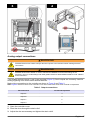
Mounting components and dimensions
C A U T I O N
Personal injury hazard. Only qualified personnel should conduct the tasks described in this section of the manual.
The controller can be installed on a surface, panel or pipe (horizontal or vertical). For mounting
options and instructions, refer to Figure 2, Figure 3 on page 8, Figure 4 on page 9, Figure 5
on page 10 and Figure 6 on page 11.
For horizontal pipe mounts, the mounting feet (Figure 2) must be attached to the mounting bracket in
a vertical position.
For both horizontal and vertical pipe mounts, attach the mounting bracket to the controller as shown
in Figure 5 on page 10.
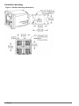
Figure 2 Mounting components
1 Mounting foot (2x) 6 Flat washer, ¼-inch ID (4x)
2 Sealing gasket for panel mount, Neoprene 7 Lock washer, ¼-inch ID (4x)
3 Bracket for wall and pipe mounting 8 M5 x 0.8 Keps hexnut (4x)
4 Vibration isolation gasket for pipe mount 9 Pan head screws, M5 x 0.8 x 100mm (4x) (Used for
variable diameter pipe mount installations)
5 Vibration isolation washer for pipe mount (4x) 10 Pan head screws, M5 x 0.8 x 15 mm (4x)
Note: A bracket for panel mounting is available as an optional accessory.
English
7

Controller mounting
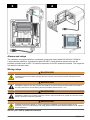
Figure 3 Surface mounting dimensions
8 English

Figure 4 Panel mounting dimensions
Note: If using the bracket (optional) for panel mounting, push the controller through the hole in the panel and then
slide the bracket over the controller on the back side of the panel. Use the four 15 mm pan head screws (supplied)
to attach the bracket to the controller and secure the controller to the panel.
English
9

Figure 5 Pipe mounting (vertical pipe)
10 English

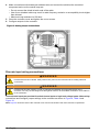
Figure 6 Top and bottom views
High-voltage barrier
High-voltage wiring for the controller is located behind the high-voltage barrier in the controller
enclosure. The barrier must remain in place except when installing modules or when a qualified
installation technician is wiring for power, alarms, outputs or relays. Do not remove the barrier while
power is applied to the controller.
Electrostatic discharge (ESD) considerations
N O T I C E
Potential Instrument Damage. Delicate internal electronic components can be damaged by static
electricity, resulting in degraded performance or eventual failure.
Refer to the steps in this procedure to prevent ESD damage to the instrument:
• Touch an earth-grounded metal surface such as the chassis of an instrument, a metal conduit or
pipe to discharge static electricity from the body.
English
11

• Avoid excessive movement. Transport static-sensitive components in anti-static containers or
packages.
• Wear a wrist strap connected by a wire to earth ground.
• Work in a static-safe area with anti-static floor pads and work bench pads.
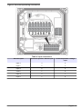
Wiring overview
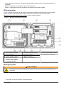
Figure 7 shows an overview of the wiring connections inside the controller with the high voltage
barrier removed. The left side of the figure shows the back side of the controller cover.
Note: Remove connector caps from the connectors before module installation.
Figure 7 Wiring connections overview
1 Service cable connection 5 AC and DC power connector
3
9 Discrete input wiring connector
3
2 4-20 mA output
3
6 Ground terminals 10 Digital sensor connector
3
3 Sensor module connector 7 Relay connections
3
4 Communication module
connector (e.g., Modbus,
Profibus, HART, optional
4-20 mA module, etc.)
8 Digital sensor connector
3
Wiring for power
W A R N I N G
Potential Electrocution Hazard. Always disconnect power to the instrument when making electrical
connections.
3
Terminals can be removed for improved access.
12 English

W A R N I N G
Potential Electrocution Hazard. If this equipment is used outdoors or in potentially wet locations, a
Ground Fault Interrupt device must be used for connecting the equipment to its mains power source.
D A N G E R
Electrocution Hazard. Do not connect AC power to a 24 VDC powered model.
W A R N I N G
Potential Electrocution Hazard. A protective earth (PE) ground connection is required for both
100-240 VAC and 24 VDC wiring applications. Failure to connect a good PE ground connection can
result in shock hazards and poor performance due to electromagnetic interferences. ALWAYS connect
a good PE ground to the controller terminal.
N O T I C E
Install the device in a location and position that gives easy access to the disconnect device and its operation.
The controller can be purchased as either a 100-240 VAC powered model or a 24 VDC powered
model. Follow the appropriate wiring instructions for the purchased model.
The controller can be wired for line power by hard-wiring in conduit or wiring to a power cord.
Regardless of the wire used, the connections are made at the same terminals. A local disconnect
designed to meet local electrical code is required and must be identified for all types of installation. In
hard-wired applications, the power and safety ground service drops for the instrument must be 18 to
12 AWG.
Notes:
• The voltage barrier must be removed before making any electrical connections. After making all
connections, replace the voltage barrier before closing the controller cover.
• A sealing type strain relief and a power cord less than 3 meters (10 feet) in length with three 18-
gauge conductors (including a safety ground wire) can be used to maintain the NEMA
4X/IP66 environmental rating.
• Controllers can be ordered with AC power cords pre-installed. Additional power cords may also be
ordered.
• The DC power source that supplies power to the 24 VDC powered controller must maintain
voltage regulation within the specified 24 VDC-15% +20% voltage limits. The DC power source
must also provide adequate protection against surges and line transients.
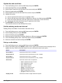
Wiring procedure
Refer to the illustrated steps that follow and Table 1 or Table 2 to wire the controller for power. Insert
each wire into the appropriate terminal until the insulation is seated against the connector with no
bare wire exposed. Tug gently after insertion to make sure that there is a secure connection. Seal
any unused openings in the controller box with conduit opening sealing plugs.
Table 1 AC power wiring information (AC powered models only)
Terminal Description Color—North America Color—EU
1 Hot (L1) Black Brown
2 Neutral (N) White Blue
— Protective Earth (PE) Ground lug Green Green with yellow stripe
English 13

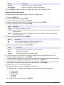
Table 2 DC power wiring information (DC powered models only)
Terminal Description Color—North America Color—EU
1 +24 VDC Red Red
2 24 VDC return Black Black
— Protective Earth (PE) Ground lug Green Green with yellow stripe
14 English

Alarms and relays
The controller is equipped with four unpowered, single pole relays rated 100-250 VAC, 50/60 Hz,
5 amp resistive maximum. Contacts are rated 250 VAC, 5 amp resistive maximum for the AC
powered controller and 24 VDC, 5A resistive maximum for the DC powered controller. The relays are
not rated for inductive loads.
Wiring relays
W A R N I N G
Potential Electrocution Hazard. Always disconnect power to the instrument when making electrical
connections.
W A R N I N G
Potential fire hazard. The relay contacts are rated 5A and are not fused. External loads connected to
the relays must have current limiting devices provided to limit current to < 5 A.
W A R N I N G
Potential fire hazard. Do not daisy-chain the common relay connections or jumper wire from the mains
power connection inside the instrument.
W A R N I N G
Potential electrocution hazard. In order to maintain the NEMA/IP environmental ratings of the
enclosure, use only conduit fittings and cable glands rated for at least NEMA 4X/IP66 to route cables in
to the instrument.
AC line (100—250 V) powered controllers
English
15

The wiring compartment is not designed for voltage connections in excess of 250 VAC.
24 VDC powered controllers
W A R N I N G
Potential electrocution hazard. AC mains powered controllers (115 V–230 V) are designed for relay
connections to AC mains circuits (i.e., voltages greater than 16 V-RMS, 22.6 V-PEAK or 35 VDC).
W A R N I N G
Potential electrocution hazard. 24 V powered controllers are designed for relay connections to low
voltage circuits (i.e., voltages less than 16 V-RMS, 22.6 V-PEAK or 35 VDC).
The 24 VDC controller relays are designed for the connection to low voltage circuits (i.e., voltages
less than 30 V-RMS, 42.2 V-PEAK or 60 VDC). The wiring compartment is not designed for voltage
connections above these levels.
The relay connector accepts 18–12 AWG wire (as determined by load application). Wire gauge less
than 18 AWG is not recommended.
The Normally Open (NO) and Common (COM) relay contacts will be connected when an alarm or
other condition is active. The Normally Closed (NC) and Common relay contacts will be connected
when an alarm or other condition is inactive (unless the Fail Safe is set to Yes) or when power is
removed from the controller.
Most relay connections use either the NO and COM terminals or the NC and COM terminals. The
numbered installation steps show connection to the NO and COM terminals.
16 English

Analog output connections
W A R N I N G
Potential Electrocution Hazard. Always disconnect power to the instrument when making electrical
connections.
W A R N I N G
Potential electrocution hazard. In order to maintain the NEMA/IP environmental ratings of the
enclosure, use only conduit fittings and cable glands rated for at least NEMA 4X/IP66 to route cables in
to the instrument.
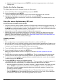
Two isolated analog outputs (1 and 2) are provided (Figure 8). Such outputs are commonly used for
analog signaling or to control other external devices.
Make wiring connections to the controller as shown in Figure 8 and Table 3.
Note: Figure 8 shows the back of the controller cover and not the inside of the main controller compartment.
Table 3 Output connections
Recorder wires Circuit board position
Output 2– 4
Output 2+ 3
Output 1– 2
Output 1+ 1
1. Open the controller cover.
2. Feed the wires through the strain relief.
3. Adjust the wire as necessary and tighten the strain relief.
English
17

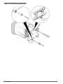
4. Make connections with twisted-pair shielded wire and connect the shield at the controlled
component end or at the control loop end.
• Do not connect the shield at both ends of the cable.
• Use of non-shielded cable may result in radio frequency emission or susceptibility levels higher
than allowed.
• Maximum loop resistance is 500 ohm.
5. Close the controller cover and tighten the cover screws.
6. Configure outputs in the controller.
Figure 8 Analog output connections
Discrete input wiring connections
W A R N I N G
Potential Electrocution Hazard. Always disconnect power to the instrument when making electrical
connections.
W A R N I N G
Potential electrocution hazard. In order to maintain the NEMA/IP environmental ratings of the
enclosure, use only conduit fittings and cable glands rated for at least NEMA 4X/IP66 to route cables in
to the instrument.
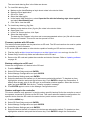
Three discrete inputs are provided for switch closure inputs or logic level voltage inputs. Make wiring
connections and configure jumper settings to the controller as shown in Figure 9, Table 4 and
Figure 10.
Note: Figure 9 shows the back of the controller cover and not the inside of the main controller compartment.
18
English
Page is loading ...
Page is loading ...
Page is loading ...
Page is loading ...
Page is loading ...
Page is loading ...
Page is loading ...
Page is loading ...
Page is loading ...
Page is loading ...
Page is loading ...
Page is loading ...
Page is loading ...
Page is loading ...
Page is loading ...
Page is loading ...
Page is loading ...
Page is loading ...
Page is loading ...
Page is loading ...
Page is loading ...
Page is loading ...
Page is loading ...
Page is loading ...
Page is loading ...
Page is loading ...
Page is loading ...
Page is loading ...
Page is loading ...
Page is loading ...
Page is loading ...
Page is loading ...
Page is loading ...
Page is loading ...
Page is loading ...
Page is loading ...
-
 1
1
-
 2
2
-
 3
3
-
 4
4
-
 5
5
-
 6
6
-
 7
7
-
 8
8
-
 9
9
-
 10
10
-
 11
11
-
 12
12
-
 13
13
-
 14
14
-
 15
15
-
 16
16
-
 17
17
-
 18
18
-
 19
19
-
 20
20
-
 21
21
-
 22
22
-
 23
23
-
 24
24
-
 25
25
-
 26
26
-
 27
27
-
 28
28
-
 29
29
-
 30
30
-
 31
31
-
 32
32
-
 33
33
-
 34
34
-
 35
35
-
 36
36
-
 37
37
-
 38
38
-
 39
39
-
 40
40
-
 41
41
-
 42
42
-
 43
43
-
 44
44
-
 45
45
-
 46
46
-
 47
47
-
 48
48
-
 49
49
-
 50
50
-
 51
51
-
 52
52
-
 53
53
-
 54
54
-
 55
55
-
 56
56


Hach SC200 User manual
- Category
- Measuring, testing & control
- Type
- User manual
Ask a question and I''ll find the answer in the document
Finding information in a document is now easier with AI
Related papers


Other documents
-
FCI MT100 Installation, Operation and Maintenance Manual
-
Rosemount 56 Advanced Dual-Input Analyzer Owner's manual
-
Bacharach GDA-400 Owner's manual
-
GE Mark VIe System Manual
-
ABB AWT420 Operating
-
-
-
Emerson Series 3000 User manual
-
 PRECISION DIGITAL PD8-6210 User manual
-
Eurotherm Action Instruments Product Handbook HA136731 Owner's manual
