Page is loading ...

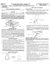
Power Cable
Die Cast Connector
Dry Wall Screw
Plastic Plug
Power Supply Box
Power Supply Box
Dry Wall Screw
Power Cable
Link Cord
Outlet
160127
ASSEMBLY AND INSTALLATION
INSTRUCTIONS
Hardware Package:
X0063 / X0064
NOTE: 1. Before installing, consult local electrical codes for wiring and grounding requirements.
2. READ AND SAVE THESE INSTRUCTIONS.
WARNING:
TO AVOID RISK OF ELECTRICAL SHOCK, BE SURE TO SHUT OFF
POWER BEFORE INSTALLING OR SERVICING THIS FIXTURE.
1. Remove the plastic plug from power supply box.
(See Fig.1)
2. Find a suitable location to mount the power
supply box. The mounting surface should be a
minimum of 1/2” thick.
3. Place the power supply box to the mounting
surface and then secure it to cabinet with two dry
wall screws. (Do not over tighten screws).
(See Fig. 1)
4. Plug the connector of link cord into the power
supply box (the link cord connects light fixture.)
Plug the connector of the power cable into power
supply box. Place the wall plug into a 120VAC
60HZ outlet. (See Fig.2)
Fig.1
Fig.2
This FIXTURE can be mounted in two ways.
A
. Installing the fixture with power cable:

Set Screw
Cover
Power Supply Box
Turn off the power at fuse or circuit box
Turn on the power at fuse or circuit box
160127
1. Remove all plastic plugs from power supply box.
(See Fig.1)
2. Find a suitable location to mount the fixture. The
mounting surface should be a minimum of 1/2”
thickness.
3. Once you have determined the position where the
light fixture will be mounted, mark the corresponding
knockout closest to your supply wire feed.
CAREFULLY REMOVE THE KNOCKOUT BY
HAMMERING A FLATHEAD SCREWDRIVER OR
PUNCH UNTIL THE SURFACE BREAKS.
Use pliers and bend it back and forth until it snaps
off if necessary. (See Fig.3)
4. Follow step 3 of A installation.
5. Unscrew the set screw from power supply box,
and then remove the cover of power supply box.
(See Fig.4)
6. Attach the die-cast connector (included) by inserting
the threaded end through the knockout. Secure the
die-cast connector to power supply box by
tightening the 1/2" lock nut. (See Fig.5)
7. Attach the conduit to the die-cast connector and
tighten the mounting screws on the die-cast
connector, so the conduit is gripped securely.
Insert the cable through the die-cast connector
with at least 6" of cable that extends past the
cabinet power supply box. (See Fig.6)
8. Take a white wire and black wire from the power
supply box and make wire connections: (See Fig.13)
---Connect the black wire from the fixture to the
black wire from the power source by using
connector.
---Connect the white wire from the fixture to the
white wire from the power source by using
connector.
Carefully put the wires back into the fixture body.
9. Re-attach the cover to power supply box and then secure it with the set screw.
10. Plug the connector of link cord into the power supply box (the link cord connects light fixture.)
Fig.3
Fig.4
Lock Nut
Die-cast
Connector
Mounting Screw
Fig.5
Fig.6
Wire Nut
Cable
Conduit
Die-cast Connector
Mounting Screw
B. Direct Wire Installation:
/