Page is loading ...

INSTALLATION INSTRUCTIONS
F Series Floodlight
© 2016 Philips Lighting Holding B.V. All rights reserved.
www.philips.com/luminaires
Part Number 443561002550 Rev. F
Page 1 of 7
IMPORTANT:
Read carefully before installing. All
work should be performed by a qualified
Electrician. These instructions may not
provide directions to cover every
variation and detail. To obtain
additional information, consult your
vendor or contact the factory directly for
assistance before attempting anything
with uncertainty. Improper installation
and/or utilization may void
manufacturer’s warranty.
This fixture must be grounded in
accordance with local codes and the
NATIONAL ELECTRIC CODE.
Failure to do so may result in serious
personal injury. HID luminaires should
be operated on grounded systems only.
Ungrounded power distribution systems
may carry high transient voltages which
can cause failure of any type electrical
equipment. Use of this equipment on
ungrounded systems will VOID THE
WARRANTY.
GENERAL:
Upon receipt, inspect for any freight
damage, which should be brought to the
attention of the delivering carrier. See
“Damage and Shortage Claims” for
proper steps in filing claims with the
carrier. Compare the catalog description
listed on the packing slip with the label
on the carton to assure you have received
the correct material.
This floodlight is designed for outdoor
lighting and should not be used in areas
with limited ventilation or within
enclosures having high ambient
temperatures. It is provided with an
integral mastfitter for mounting on a
vertical 2-3/8” OD tenon x 4-1/2” tall.
The flood light is UL listed for wet
locations (UL1598) and may be aimed
above horizontal.
WARNING: In no case mount this
floodlight to either a horizontal tenon
or inverted tenon.
IMPORTANT: The flood light optical
assembly are separately packaged.
After uncartoning, inspect for any
damage. If damage is noticed, see
“Damage and Shortage Claims Form”
(yellow) for proper steps in filing
claims with the carrier.
NOTE: Illustrations depict a 400 watt
fixture. Assembly and installation
procedures are the same for 1000 watt
and 1500 watt fixtures.

INSTALLATION INSTRUCTIONS
F Series Floodlight
© 2016 Philips Lighting Holding B.V. All rights reserved.
www.philips.com/luminaires
Part Number 443561002550 Rev. F
Page 2 of 7
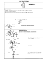
FIXTURE and BALLAST
ASSEMBLY
STEP 1
Loosen the socket nut and remove from
the socket/cord assembly. Remove socket
housing from the fixture. Pull the S.O.
cord through the socket housing.
CAUTION: Make sure the
weatherproof gasket is between the
socket and inside of socket housing as
shown in FIGURE 1.
Install the socket nut and tighten to
15 ft-lbs. to assure a good weatherproof
seal.
LAMPING
STEP 2
Prior to installing lamp into socket,
check to make sure it is the correct type
and wattage.
CAUTION: Observe lamp
manufacturer’s recommendations and
restrictions on lamp operation,
particularly regarding ballast type
and burning position.
STABILUX LAMP SOCKET
STEP 3
This floodlight has a stabilux lamp
socket that grips the top of the lamp
which holds the lamp in alignment and
offers protection against breakage when
the fixture is subjected to vibration.
Before installing lamp into the fixture
you will need to determine the correct
stabilux holder required for the particular
lamp purchased. This determination is
dependent on the lamp shape. “BT”,
“ED” or “E” shaped (See FIGURE 2).
BT SHAPED LAMPS
Install lamp into socket. Attach socket
housing to the fixture, making sure end
of lamp securely engages the fiberglass
tape-lined stabilux (split collar). Be sure
socket housing gasket is seated properly,
and then tighten the screws securely.
E OR ED SHAPED LAMPS
This lamp shape is primarily found in
400 watt size lamps. The “BT” stabilux
collar must be removed before installing
an “E” or “ED” shaped lamp. This is
accomplished by compressing the “BT”
(split collar) by hand and removing
from the fixture. Inside the stabilux
cavity of the fixture there is a “E” lamp
stabilux (found on 400 watt floodlights
only). Bend the “E” stabilux (fiberglass
tape-covered cone) down into the
fixture. Install lamp into socket. Attach
socket housing to the fixture, making
sure the “E” stabilux cone firmly
engages the lamp dimple. Be sure the
socket housing gasket is seated
properly, and then tighten the screws
securely.
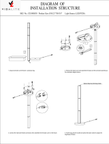
BALLAST ASSEMBLY
STEP 4
Attach fixture mounting arms to ballast
enclosure/mastfitter assembly with the
4-1/2” long machine bolt, 1/2” flat
washer, 1/2” split-lock washer, and
1/2 – 13 hex head nut (provided in
fixture hardware kits). Arms should be
set in their proper aiming position.
Tighten the 1/2 – 13 hex head nut
slightly (See FIGURE 3)
STEP 5
Mount fixture head to mounting arms.
Install star washers, and attach the two
1-1/2” long machine bolts and 1/2”
split-lock washers (provided in fixture
hardware kit). Fixture at this stage may
be set at the proper vertical aiming
angle by using the degree markings on
the mounting ears. (Aiming angle may
also be set after the fixture and ballast
assembly are mounted to the pole or 2-
3/8” OD vertical tenon). If proper
aiming angle has been set, tighten the
two 1-1/2” long machine bolts
securely, then tighten the 1/2 – 13 hex
head nut on mastfitter to 25 ft-lbs (See
FIGURE 4).

INSTALLATION INSTRUCTIONS
F Series Floodlight
© 2016 Philips Lighting Holding B.V. All rights reserved.
www.philips.com/luminaires
Part Number 443561002550 Rev. F
Page 3 of 7
FIXTURE WIRING
This fixture must be wired in accordance
with the NEC and applicable local codes.
WARNING: Proper grounding is
required to insure personal safety.
Connect the green or bare copper fixture-
ground lead to a suitable ground
connector. Use approved connectors for
all electrical connections.
STEP 6
Unscrew and remove the cable
connector nut from cable connector on
side of ballast mastfitter, (See
FIGURE 5). Remove the rubber
grommet from cable connector body.
Slide cable connector nut up the S.O.
cord, then slide the rubber grommet
approximately 3” up the S.O. cord.
Insert S.O. cord into cable connector
body, then attach and securely tighten
the cable connector nut to 15 ft-
lbs.
STEP 7
Remove inspection plate and gasket
from back of mastfitter by removing
the two screws (See FIGURE 5).
Mount fixture/ballast assembly to 2-
3/8” OD vertical pipe tenon (by others)
after pushing branch circuit lead wires
(by others) through the mastfitter and
out inspection plate opening. Service
may also be made by removing the
1/2” pipe plug from the mastfitter and
attaching a proper watertight connector
(by others), and then inserting an S.O.
cord with branch circuit lead wires (by
others). Tighten the two 3/8” square
head set screws on the side of the
mastfitter against the pipe tenon to 8
ft-lbs.

INSTALLATION INSTRUCTIONS
F Series Floodlight
© 2016 Philips Lighting Holding B.V. All rights reserved.
www.philips.com/luminaires
Part Number 443561002550 Rev. F
Page 4 of 7
STEP 8
Make proper electrical connections as
indicated on wiring diagram located on
the ballast enclosure. Connect line lead
to the black lead, neutral lead to white
and ground lead to the green grounding
screw inside the mastfitter splice box.
On 120 volt and 277 volt systems,
connect the voltage supply lead to the
ballast lead marked with the voltage
marker. Connect the neutral supply lead
marked COM.
On other voltage systems, connect one
supply lead to the ballast lead marked
with the proper voltage and the other
supply lead to the ballast lead marked
COM.
WARNING: On quad voltage ballast
(QV), leads not required should
always remain with the insulated
connector intact.
STEP 9
Before closing the mastfitter splice box,
check to be sure proper voltage leads
have been selected to match the supply
voltage before energizing. Improper
wiring may result in ballast failure and
void warranty.
Ensure wires in pole are strain-relieved.
Place connected wires into the mastfitter
splice box and replace inspection plate
and gasket. Tighten the inspection plate
screws securely to 1 ft-lbs.
AIMING
STEP 10
If fixture was not aimed during assembly
(step 5), loosen the two 1-1/2” long
machine bolts on mounting ears. Set
fixture to proper aiming angle by using
either the degree markings on the
mounting ears or the built-in aiming
device on top of fixture.
OPTIONS
Vertical Floodlight
Follow steps 1 through 3 above. Next
attach the “U” bracket to the ballast
mastfitter as shown in FIGURE 6.
CAUTION: the two holes in the
bracket for the 3/4” long bolts must be
toward the top as shown in FIG. 6.
Mount fixture to the “U” bracket and
attach the three 3/8”-16 mounting bolts
and lock washers.
IMPORTANT: The 1/2” long bolt is
centered over the fixture flange and to
the bottom of the mount. Tighten all
bolts to 30 ft-lbs.
Follow wiring and aiming instructions
covered in steps 6 through 10 above.
LQ-70 Hot/Cold Quartz Restrike
with Time Delay
Automatically controls an integral quartz
lamp (provided by user) anytime the
main lamp is extinguished and the ballast
is energized. (Q150/DC is recommended
for all HID lamps except 1000 watt,
which have two DC Bayonet base
sockets, two 250w (250Q/DC) quartz
lamps for -70°F operation or two 150w
quartz lamps for normal LQ operation
are required).
Following a cold start or a momentary
power interruption the quartz lamp is
energized by a solid state controller
located inside the fixture housing. The
quartz lamp remains on until after the
main HID lamp reaches approximately
40% light output. Combined current of
the quartz lamp and HID lamp never
exceed the main lamp current at full
output.
The quartz socket(s) is prewired with
S.O. cord off the back side of the fixture
housing and is wired to the ballast by
removing the 1/2” pipe plug and
installing a watertight connector
(provided by user), and then inserting the
S.O. cord and wire to the ballast as
shown per the wiring diagram.
Eclipse
Provides full bright to blackout to instant
full bright illumination for special
theatrical effects in indoor arenas and
stadiums.
DANGER: Not suitable for outdoor
applications must be used indoors
only.

INSTALLATION INSTRUCTIONS
F Series Floodlight
© 2016 Philips Lighting Holding B.V. All rights reserved.
www.philips.com/luminaires
Part Number 443561002550 Rev. F
Page 5 of 7
Requires special remote “MPB” Eclipse
Bi-Level™ ballast for satisfactory
operation.
Assemble two support brackets to
motor/shutter support plate with four 8-
32 x 1/2” screws and 8-32 nut/lock
washer as shown in FIGURE 7.
Remove two each 1/4-20 screws from the
fixture mounting ears and assemble
eclipse shutter to the fixture using the
two 1/4-20 screws previously removed.
WARNING: Make sure screws are
completely tightened. Failure to
completely tighten these screws
can/will lead to equipment failure
and/or personal injury.
Install the four 10-24 x 3/8” phillips
threaded cutting screws across the top
front of the fixture (four cored holes)
WARNING: Failure to install these
screws can lead to erratic operation,
equipment failure and/or personal
injury.
Socket and lamp installation are similar
to steps mentioned for the standard
floodlight. Fixture assembly is also
similar, except the mounting arms will be
attached to appropriate mastfitter (MF-1,
MF-2 or HV-1) for fixture without
integral ballast. S.O. socket cord should
be attached to the remote ballast
secondary. Wire per applicable wiring
diagram packed with the Eclipse Bi-
Level™ ballast.
ACCESSORIES
F-F1 or F-F2 Ballast Fusing
If individual fusing or ballast is desired,
accessory fusing is available and may be
installed during wiring of the ballast.
Unless otherwise specified, fuses
furnished for all ballast 1500 watt
through 150 watt will be KTK 30 amp
rated. 100 watt and below will be KTK
10 amp rated.
Fuses and holders are usually the
external type (see FIGURE 8) and
should be wired according to diagram
shown. F-F1 fuse kits are a single fuse
for 120V or 277V. F-F2 fuse kits are a
double fuse for 208V, 240V, or 480V.
FB1 Flat Base Mount
Flat mounting casting with provisions for
vertical 2-3/8” OD tenon (by others) for
mounting to flat horizontal surfaces.
Mounting hardware for anchoring
provided by user. CAUTION: Limit
height of tenon to no more than 8”.
(See FIGURE 9).
PX-1 Cross Arm Bracket
Cast aluminum angle bracket with 2-3/8”
OD vertical tenon for installing
floodlights to wooden or steel cross-
arms. CAUTION: Back plate of
bracket installs to cross member
opposite fixture lens.
There are five 9/16” mounting holes for
securing the PX-1 to the cross member,
three of which can be utilized without
bolt interference. These are the two on
top and the lower horizontal hole in the
back plate. As a minimum these three
holes must be utilized. Mounting
hardware 1/2” bolts provided by user.
(See FIGURE 10).
PM-(*) Wood Pole Mounting Brackets
Aluminum wood pole mounts with
vertical 2-3/8” OD tenon for mounting
floodlights to wood poles with 6”
minimum to 12” maximum diameter.
(See FIGURE 11)
(*) Number which represents the number
of floodlights (maximum is four) that can
be mounted to a PM wood pole bracket
Example: PM2 will handle up to two
floodlights.
SK-100 or SK-40 Top Glare Shield
Remove two or one lens retainer fastener
screw(s) on each side of the fixture lens
frame. Install shield to the top of fixture
utilizing the four cored holes and the
four thread cutting screws (provided in
kit). Secure the side of the shield to the
lens retainer using the one or two lens
retainer screws previously removed.
Tighten all screws securely (See FIG 12)
AL-10-F or AL-4-F Auxiliary
Polycarbonate Lens
Remove one lens retainer screw from
each corner of the fixture lens frame.
Assembly hardware and install auxiliary
lens as shown in FIGURE 13.
SMB-1000 or SMB-400 Shock
Mounting Brackets
For mounting flooolights without integral
ballasts in applications where severe
vibrations may be present.
CAUTION: Ballast must be remote
mounted away from the vibration area
and must be suited for outdoor use or
indoor use depending upon where they
can be mounted. If subjected to the
weather they must be the outdoor type
approved for wet locations (See
FIGURE 14).
Socket and lamp installation will be the
same as covered in steps 1 through 3. To
install the fixture in the shock mounting
frame (discard the standard mounting
arms as they are not required when using
the “SMB” brackets), remove the two
1/2” x 1-1/4” machine screws that holds
the back brace (part B) and slide fixture
into the frame. IMPORTANT: Make
sure the lens frame is properly resting
in the frame. Re-install the back brace,
making sure the back plate with neoprene
rubber pads rest firmly against the back
of the fixture, tighten screws securely.
Mount fixture/shock mounting bracket to
a suitable flat surface utilizing the two
9/16” slots in the frame yoke (part A).
Secure with two 1/2” mounting bolts
(provided by user). Aim fixture as
required and tighten all bolts to 30 ft-lbs.
Make proper electrical connections in
accorda
nce to

INSTALLATION INSTRUCTIONS
F Series Floodlight
© 2016 Philips Lighting Holding B.V. All rights reserved.
www.philips.com/luminaires
Part Number 443561002550 Rev. F
Page 6 of 7
NEC and local codes. Follow wiring
instruction on ballast.
IMPORTANT: If high pressure
sodium remote ballast is used make
sure the ballast is installed within the
distance limitations published by the
ballast manufacturer.
PCM-1 Photocell Receptacle Only
Remove 1/2” pipe plug from the ballast
mastfitter base. Thread the 1/2”
photocell receptacle into the mastfitter
base, tighten securely. Check to see that
the photocell (provided by user) is of
proper voltage and wattage. Wire in
accordance to wiring diagram.
(See FIGURE 15).
WG-10 or WG-4 Wireguard
Attach wireguard to cored holes on top
and bottom of fixture with thread cutting
screws provided in kit (see FIGURE
16).
MF-1 Mastfitter for Less Ballast
Models
Allows fixture head to be remote
mounted on a vertical 2-3/8” OD tenon x
4-1/2” tall. Attach fixture mounting arms
to the MF-1 using hardware as covered
in steps 4 and 5 of fixture assembly.
Remove pipe plug from MF-1 and route
S.O. cord through a watertight cable
connector (provided by user) for internal
wiring to the remote ballast. Or, wiring
can be external to an appropriate
junction box or similar device (See
FIGURE 17).
HV-1 Trunion Base for Less Ballast
Models
Can be mounted to any suitable
horizontal or vertical surface suited for
the purpose. Calibrate in 10° increments
(0°-90°) for horizontal adjustment. There
are three mounting holes, 7/16” nominal
diameter for 3/8” mounting bolts
(provided by user) for mounting the
HV-1 attach fixture mounting arms to the
HV-1 using hardware as covered in steps
4 and 5 of fixture assembly (See
FIGURE 18).
WB-1 Wall Mounting Bracket
For mounting floodlight with ballast or
less ballast models to a flat vertical
surface only. There are four 9/16”
nominal mounting holes in the back plate
for 1/2” mounting bolts (provided
by user). Wiring of fixture can be done
internally (see wiring instructions)
through the bracket for applications
where the wiring box is flush mounted.
Or, can be wired externally to an
appropriate junction box or similar
device. (See FIGURE 19).
WG-10, WG-4
AL-10, AL-4

INSTALLATION INSTRUCTIONS
F Series Floodlight
© 2016 Philips Lighting Holding B.V. All rights reserved.
www.philips.com/luminaires
Part Number 443561002550 Rev. F
Page 7 of 7
Philips Lighting North America Philips Lighting Canada Ltd.
Corporation 281 Hillmount Road,
200 Franklin Square Drive, Markham ON, Canada L6C 2S3
Somerset, NJ 08873, USA
WB-5 Surface Wiring Box
For use with WB-1 wall bracket. Serves
as a wiring compartment and used where
surface mounted conduit feed is used.
Tapped at top, bottom, and back for 3/4”
NPT conduit. Gasket provided for
sealing box to the WB-1. Mounting
hardware (1/2” mounting bolts) provided
by user. The WB-5 box is supported by
the same bolts used to support the WB-1
and need to be long enough to secure
both the WB-1 and box to the wall. The
box straddles the four mounting bolts.
(See FIGURE 20).
TH-1 Hanger for Less Ballast Models
For mounting floodlights on standard
lowering devices (by others). Base of
TH-1 is tapped for 1-1/4” NPT conduit.
For 1” tap a 1-1/4” to 1” reducer
(provided by user) is required. Thread
TH-1 on to lowering device and tighten
set screw to lock to the stem. Install
floodlight to TH-1 covered in steps 4 and
5 of fixture assembly.
(See FIGURE 21).
/